MASCHIO GASPARDO KATIA 650 User guide

KATIA 650
BRACCIO IDRAULICO DECESPUGLIATORE HYDRAULIC FLAIL-EDGER MOWER
Cod. EGL0025OS 2017
IT - USO E MANUTENZIONE / PARTI DI RICAMBIO
EN - USE AND MAINTENANCE / SPARE PARTS
*) Valido per Paesi UE
*) Valid for EU member countries

Libretto n. EGL0025OS
Edizione 2017
ALLEGATO ALLA DICHIARAZIONE DI CONFORMITA'
AI REQUISITI ESSENZIALI DI SICUREZZA E DI SALUTE
DETTATI DALLA DIRETTIVA 2006/42/CE E SUCCESSIVE MODIFICAZIONI
Manual nr. EGL0025OS
Edition 2017
ENCLOSED TO THE CONFORMITY DECLARATION
FOR THE ESSENTIAL REQUIREMENTS OF SAFETY AND HEALTH
DICTATED BY 2006/42/CE DIRECTIVES AND FOLLOWING MODIFICATIONS
pag. 2 ITALIANO

INDICE :
Introduzione pag. 4
Sicurezza pag. 4-5
Targhette di sicurezza e identificazione pag. 6-7
Trasporto pag. 8
Immagazzinamento pag. 8
Messa in servizio pag. 9
Scelta del trattore pag. 9
Descrizione della macchina pag. 10
Caratteristiche tecniche pag. 11-12
Istruzioni per l' uso e la manovra pag. 13/16a
Istruzioni per la manutenzione pag. 17/19
Messa a riposo pag. 19
Circolazione stradale pag. 16
Garanzia pag. 20
Parti di ricambio pag. 20/47
Schemi Elettrici pag. 48-49
ENGLISH
INDEX :
Introduction page 4
Safety page 4-5
Safety plates and identification page 6-7
Transport page 8
Warehousing page 8
Starting page 9
Tractor’s choice page 9
Machine’s description page 10
Technical specifications page 11-12
Instructions for use and manoeuvre page 13/16a
Maintenance instructions page 17/19
Machine out of service page 19
Road traffic page 19
Warranty page 20
Spare parts page 20/47
Electric Plants page 48-49
pag. 3
INTRODUZIONE Il presente manuale, fornisce al personale addetto, le norme e i dati necessari

per un uso sicuro e una corretta manutenzione della vostra macchina.
Leggete e seguite attentamente le istruzioni e soprattutto siate prudenti.
Qualsiasi programma di prevenzione non può avere successo senza la
cooperazione del personale direttamente responsabile dell'attrezzatura.
Un largo numero di incidenti può essere prevenuto solo dall'operatore,
che essendo a conoscenza dei reali pericoli opera in modo da evitarli.
Ricordate che un operatore attento, che agisce con cura e responsabilità,
può evitare gravi incidenti , più di qualsiasi programma di prevenzione.
La ditta costruttrice, declina ogni responsabilità per fatti accaduti per
negligenza, incuria, o per mancata osservanza delle norme di sicurezza.
Ricordate che la manutenzione secondo le indicazioni di seguito riportate,
è indispensabile per mantenere sicura ed efficiente la vostra macchina.
Norme generali di sicurezza :
- In questo manuale e sulle targhette applicate sulla macchina, troverete
le regole di prevenzione che riguardano la vostra sicurezza e delle persone
che lavorano con voi, leggete con attenzione, non osservando tali istruzioni
potreste causare seri infortuni o morte.
Troverete questo simbolo ,solo o seguito da particolari pittogrammi,
ogni qualvolta sarà necessario fare particolare attenzione per evitare
pericolosi incidenti.
Di seguito troverete una lista delle più importanti precauzioni di
sicurezza.
1) La macchina può essere utilizzata esclusivamente da personale istruito
all' uso della macchina stessa. Non permettere l' uso della macchina a
nessun operatore che non sia a conoscenza dei rischi e delle istruzioni
riportate nel presente manuale.
2) Assicuratevi che non vi siano persone non autorizzate nel raggio di azione
della macchina,( almeno 50 metri ) ; fate particolare attenzione ai bambini.
3) Verificare la stabilita del trattore, con macchina al massimo sbraccio di
lavoro. Questa operazione deve essere eseguita su terreno piano;
mantenendo la testata trinciante il più vicino possibile a terra, e allontanandola
lentamente dal trattore, fino al raggiungimento del massimo sbraccio.
4) Non lavorare su terreni con pendenze eccessive, tali da compromettere
la stabilità del trattore, o su terreni di scarsa consistenza.
5) Indossare cuffie o tappi protettivi per l'udito.
pag. 4
INTRODUCTION
The present manual provides staff with all the regulations and details necessary
for safe use and proper maintenance of your machine.
Read the instructions very carefully and, above all, follow them with great care.
No programme of prevention can be successful without the co-operation of the
personnel directly involved with the equipment.
A large number of accidents can be prevented by the operator alone, who being
aware of the real dangers can work in such a way as to avoid them.
Remember that a careful operator, acting with care and responsibility, can avoid
serious accidents, much more than any prevention programme.
The manufacturing company declines any responsibility for accidents occurring
due to negligence, lack of care or failing to comply with the safety regulations.
Remember that maintenance carried out according to the instructions given in the
following pages is indispensable in keeping your machine safe and efficient.
General safety regulations:
You will find the rules of prevention both in this manual and on the plates placed
on the machine. They concern your safety and for others working with you so read
them carefully. If you do not comply with these instructions you could cause
serious injury or death.
You will find this symbol, by itself or followed by special illustrations,
whenever it is necessary to pay particular attention and to avoid
dangerous accidents. The following is a list of the most important safety
precautions.
1) The machine may only be operated by staff instructed in its use.
Do not allow the machine to be used by any operator who is not aware of the
risks and the instructions referred to in this manual.
2) Ensure that no unauthorised personnel come within range of the workings of
the machine (at least 50 metres) paying particular attention to children.
3) Ascertain the stability of the tractor while the machine is at its maximum
extension. This operation must always be carried out on a level terrain, keeping
the cutting head as near as possible to the ground and gradually moving it
away from the tractor until it reaches its maximum extension.
4) Never work on slopes that would jeopardise the tractor’s stability or on terrains
that are unstable or inconsistent.
5) Wear headphones or ear plugs to protect your hearing.
6) Quando non utilizzate la macchina, fermate il trattore su terreno piano con il freno di stazionamento e la prima marcia inseriti, appoggiate la testata

trinciante a terra, disinserite la presa di forza, spegnete il motore e togliete
la chiave di avviamento
7) Circolando o lavorando su strade pubbliche, rispettate scrupolosamente
le norme dettate dal codice della strada in vigore nel vostro stato.
8) Non effettuare lavori di manutenzione o pulizia senza avere prima staffato
la macchina al trattore come di seguito illustrato.
9) Non fare nessun lavoro di manutenzione, di controllo, o di pulizia quando
la macchina è in movimento, operate come successivamente indicato alla
sezione manutenzione.
10) Alcuni rami del circuito di azionamento dei cilindri, possono rimanere in
pressione anche quando la macchina è ferma; non intervenire per
sostituire parti dell'impianto, senza avere prima scaricato la pressione,
come indicato successivamente alla sezione manutenzione.
(Questi interventi possono essere eseguiti solo da personale specializzato )
L' olio in pressione potrebbe penetrare nella pelle o negli occhi; se ciò
dovesse accadere, richiedere con urgenza l' intervento di un medico.
11) In seguito all'usura o alla non corretta regolazione dei componenti
oleodinamici, potrebbe verificarsi un surriscaldamento dell' olio
contenuto nel serbatoio, attendere che la temperatura si abbassi prima di
intervenire per qualsiasi motivo.
12) Non maneggiare i filtri dell'olio a mani nude, un prolungato contatto con
gli oli può procurare irritazioni e malattie della pelle;proteggere le mani
con guanti di gomma antiolio.
13) La sicurezza della vostra macchina dipende particolarmente dal suo
Stato di efficienza, rispettate quindi le istruzione e le tabelle di
manutenzione.
14) Non richiudere la macchina in posizione di trasferimento prima che
l' albero dell' apparato trinciante si sia completamente arrestato.
15) Non lavorare senza le protezioni parasassi installate sulla testata
trinciante.
16) Non manomettere i sistemi di sicurezza e la taratura delle valvole di controllo.
6) When the machine is not in use, bring the tractor to a halt on level ground
with the handbrake on and the first gear engaged, rest the cutting head on the
ground, disengage the power take-off, switch off the engine and remove the
starting key.
7) When moving about or working on public roads, scrupulously observe the
regulations enforced by the current highway code of your country.
8) Do not carry out maintenance work, inspections or cleaning operation
without first fixing the machine to the tractor as illustrated.
9) Do not do any maintenance work, inspections or cleaning while the machine
is moving. Carry out these operations as indicated in the section which follows,
entitled ‘Maintenance’.
10) Some arms of the drive circuit in the cylinders may remain under pressure
even when the machine is motionless. Do not replace the machine parts
without first discharging the pressure as indicated in the following section
entitled ‘Maintenance’. (These operations may only be carried out by qualified
personnel). The pressurised oil could penetrate the skin or eyes; if this should
happen call a doctor immediately.
11) As a result of wear or incorrect regulation of the hydraulic components, the
oil in the oil tank may overheat.
In which case wait until the temperature goes down before intervening.
12) Never handle the oil filters with bare hands as a prolonged contact with oil
can bring about irritations and disease of the skin.
Protect your hands with oil-resistant rubber gloves.
13) The safety of your machine depends to a great degree on its condition.
Therefore follow the instructions and the maintenance tables very carefully.
14) Do not shut down the machine when in a position of transfer before the
shaft of the cutting apparatus has come to a complete standstill.
15) Never work without first affixing the stone guard to the
cutting head.
16) Do not tamper with the safety system or the calibration of the control valve.
pag. 5
Targhette di sicurezza :

- Le seguenti targhette di sicurezza sono collocate sulla macchina, nelle zone
indicate dal disegno sotto riportato. Esse sono rivolte alla sicurezza vostra e delle
persone che lavorano con voi.Girate attorno alla vostra macchina col presente
manuale aperto, e prendete nota della posizione e del contenuto di ogni segnale
di pericolo.
Ripetete questa operazione, assieme agli operatori destinati all'uso della
macchina.
Fate attenzione a non danneggiare le targhette, e se ciò avviene, sostituitele
richiedendole al vostro rivenditore o direttamente alla ditta costruttrice.
Safety plates :
-The following safety plates are placed on the machine, as shown in the
drawing below.
They concern your safety and for others working with you .
Go round your machine with this manual open and note the position and
content of each signal of danger .
Repeat this operation together with all the operators who will use the machine .
Pay attention not to damage the plates, and, in case it happens, replace the
plates ordering them through your distributor or directly to the builder company .
pag. 6

Targhetta N.1
Leggere attentamente il manuale di
uso e manutenzione della macchina,
prima di iniziare a operare. Durante il
lavoro, osservare scrupolosamente
le istruzioni e le norme di sicurezza.
Plate Nr.1
Read the Use and Maintenance
manual of the machine carefully
Before using the machine.
During work, observe carefully the
instruction and safety regulation.
Targhetta N. 2
Spegnere il motore e disinserire la
chiave di avviamento del trattore o
della macchina operatrice, prima di
effettuare qualsiasi lavoro di
riparazione o manutenzione.
Plate Nr.2
Switch off the engine and remove
the tractor’s or machine starting key
before doing any repairs or
maintenance work.
Targhetta N. 3
Pericolo di taglio del piede; coltelli in
rotazione. Non avvicinare i piedi o le
mani.
Plate Nr.3
Rotating knives: cutting danger for
feet. Do not approach with feet or
hands .
Targhetta N. 4
Pericolo di lancio sassi o
materiale vario ;
mantenersi a una
distanza di sicurezza di
almeno 50 metri.
Plate Nr.4
Possible escape of
stones or materials :
keep a safety distance of
minimum 50 meters.
Targhetta N. 5
Attendere che tutti i componenti
della macchina si siano
completamente arrestati, prima di
intervenire per un controllo o una
manutenzione.
Plate Nr.5
Do not do any inspections or
maintenance while the machine is
moving .
Targhetta N. 6
Pericolo di schiacciamento, non
sostare nel raggio di azione della
macchina. Bloccare i cilindri con
l'apposito dispositivo, prima di
intervenire per un controllo o una
manutenzione.
Plate Nr.6
Danger of crushing : do not stand in
the machine working area . Lock the
cylinders with its suitable device,
before doing any inspections
or maintenance .
Targhetta N. 7
Pericolo di scariche elettriche.
Tenersi ad una distanza di
sicurezza dalle linee elettriche.
Plate Nr.7
Danger of electric discharge .keep a
safety distance from electrical
mains.
Targhetta N. 8
Identificazione della macchina,
marcatura " CE ".
Plate Nr.8
Machine’s identification, " EC "
mark .
pag. 7

a) Trasporto, movimentazione, immagazzinamento della macchina :
Prima di sollevare la macchina per trasportarla accertarsi che sia chiusa
nella posizione di trasferimento ; che i bloccaggi " B "siano serrati e che i
piedini " P " di appoggio siamo correttamente posizionati. ( vedi sotto )
La massa della macchina è indicata nella targhetta di identificazione della
macchina stessa .( vedi pag. 12 )
I punti di aggancio per il sollevamento sono indicati nello schema seguente,
e contrassegnati dall'apposita targhetta, sotto riportata.
La macchina deve essere immagazzinata al riparo dagli agenti atmosferici,
ad una temperatura compresa tra 0 e 30 °C.
a) Transport, handling and warehousing of the machine
Before lifting the machine for its transport, ensure that it is closed in the transfer
position, that the “S“ clamping screw is in the suitable housing, and that the P
support is correctly positioned (see below).
The hitching points for the lifting are shown in the following diagram, and tagged
by the suitable plate, reproduced below.
For machine's dimensions and weight see page 12.
The machine must be stored protected from rain and snow, at a temperature
from 0 to 30°C.
Pa
pag. 8

b) Messa in servizio della macchina , scelta del trattore :
Prima di mettere in servizio la macchina, leggere attentamente tutto il
contenuto del presente libretto di istruzioni, che dovrete conservare con cura e
tenere sempre a portata di mano, per una eventuale consultazione.
La macchina deve essere staffata ad un trattore con attacco a tre punti di
categoria adeguata ( vedi pag. 12 ) con presa di forza a 540 min -1, per pompe
ad ingranaggi; o presa di forza a 1000 min -1, con pompa a pistoni.
la massa totale minima è indicata a pag.12 .
Non superare in nessun caso le masse massime ammesse sugli assi dal
costruttore del trattore ( rilevare le informazioni necessarie dal libretto di
istruzione del trattore, oppure richiederle al costruttore stesso.)
Regolare l'altezza da terra della macchina (400 mm circa), e bloccare il
sollevatore con le apposite catene o con i tenditori laterali;per evitare
sovraccarichi è consigliabile inoltre bloccare i bracci del sollevatore stesso con
tenditori di fissaggio, da noi forniti a richiesta, o con analogo sistema.
Posizionare il gruppo leve di comando in posizione comoda all'operatore, in
zona sicura, protetta da urti accidentali.
Dopo lo staffaggio , collegare la macchina alla presa di forza del trattore con
un albero cardanico di lunghezza e classe adeguata; la potenza massima
assorbita dalla macchina è indicata a pag. 12.
Per il collegamento, l'uso e la manutenzione del cardano, leggere
attentamente le istruzioni fornite dal costruttore. Impiegare esclusicamente alberi
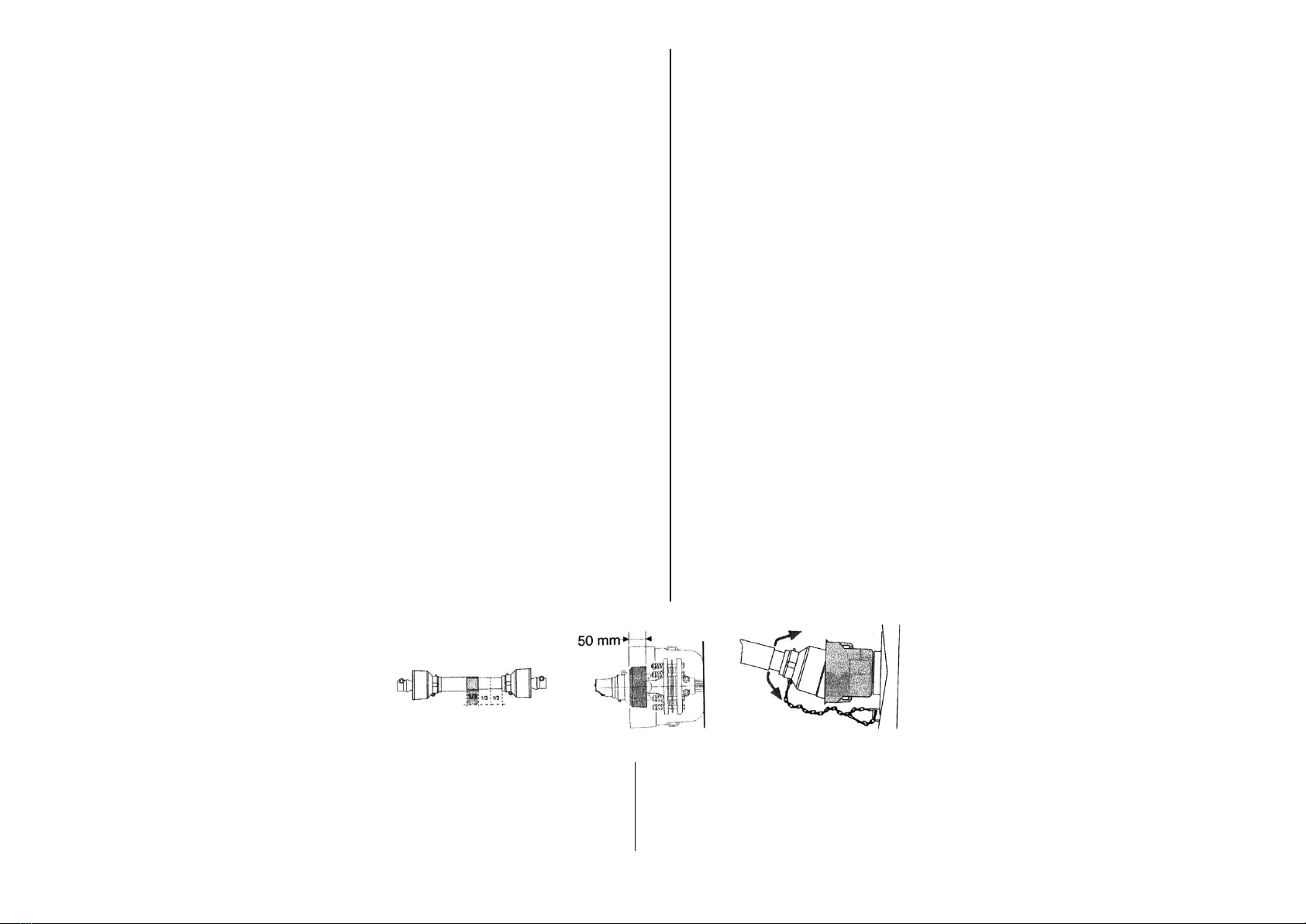
cardanici muniti di certificazione "CE". I tubi telescopici del cardano devono
sovrapporsi per almeno 1/3 della loro lunghezza. Agganciare le catenelle
antirotazione della protezione.
La sovrapposizione della protezione applicata sulla presa di forza, con la
protezione del cardano dovrà comunque essere di almeno 50 mm. Dopo l'uso,
riporre il cardano con cura, facendo attenzione a non danneggiare le protezioni.
b) Machine’s starting, choise of the tractor :
Before starting the machine, read this instructions manual carefully and keep it
with care and within reach, in case you will need to consult it.
The machine must be fixed to the tractor with athree point linkage of suitable
category ( see page 12 ) with 540 rpm power take off , if you have gear pump;
and 1000 rpm if you have piston pump
The minimum total weight is indicated at page.12 .
Never exceed the maximum weights allowed on the axles by the tractor’s builder
(look for the tractor’s instruction manual, or ask them to the builder).
Adjust the machine’s height from the ground ( about 400 mm ), and fix the
elevator with its chains or fixing links .
Fix the control levers group in a position suitable for the operator, safe and
protected from fortuitous impact .
After having installed the machine connect it to the tractor’s power take-off; the
machine’s maximum absorbed power is indicated at page. 12.
For the cardan shaft‘s connection, use and service, read the builder‘s instruction
carefully.
Use only EC certified cardan shaft .
The cardan shaft‘s telescopic tubes must be used with a maximum extension of
2/3 of the total length . The power takeoff‘s protection and the cardan shaft‘s one
must be overlapped at least 50 mm. Hook the protection‘s anti-rotation chains.
After the use, when you put the cardan shaft away, pay attention not to damage
the protections.
Prima della messa in funzione, effettuare il
controllo del livello degli oli e dello stato i
ingrassaggio generale; e verificare che i
rubinetti di aspirazione sul serbatoio siano
aperti.( vedi pag.16 ), e disinserire i sistemi
di bloccaggio per il trasporto.(vedi pag 8).
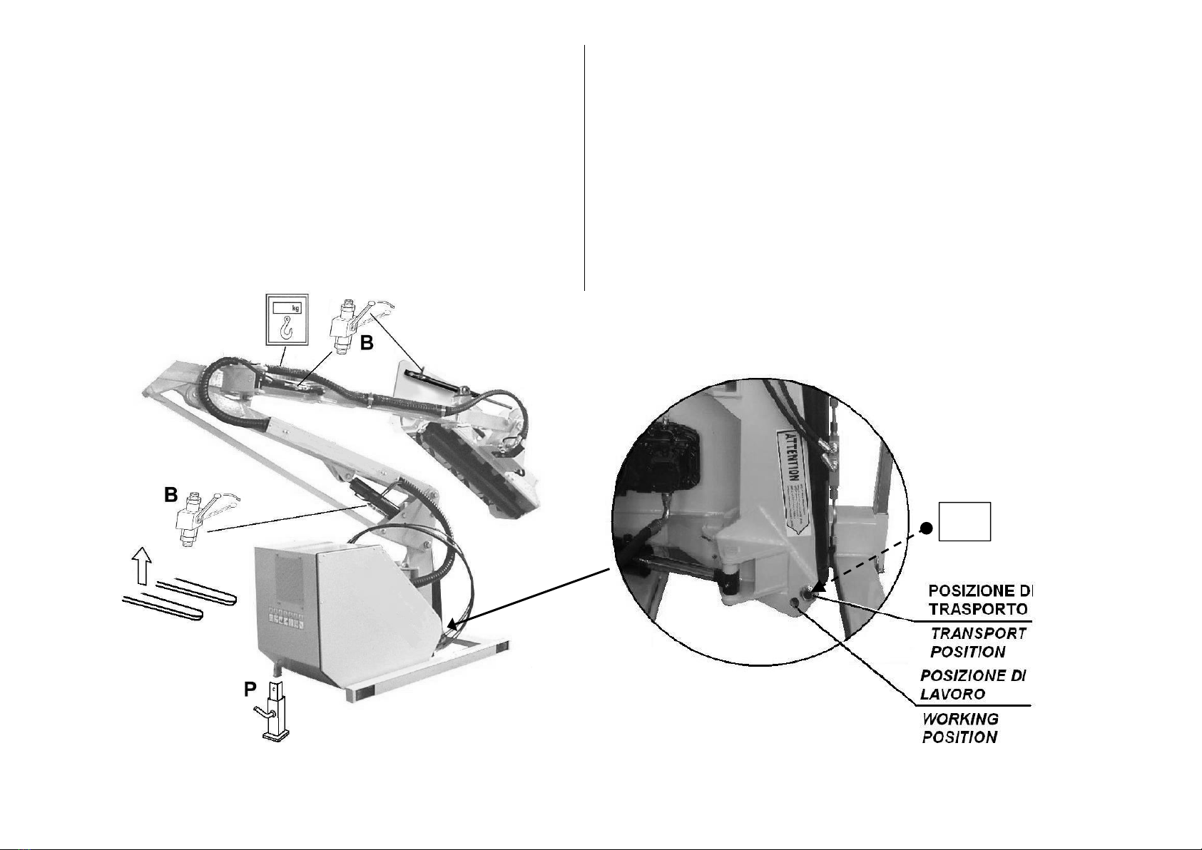
Posizione TRASPORTO / LAVORO : vedi pag. 8; prima di
Before the machine‘s starting, check the general
greasing. Verify that the suction valve on the
tank are completely open. (See page 16),
disconnect the locks for the transport . (See
page 8 )
iniziare il lavoro, spostare il perno Pa, dalla posizione
superiore (trasporto) , alla posizione inferiore (lavoro).
Tale operazione, deve essere eseguita con la testata
appoggiata al terreno.
TRANSPORT / WORKING Position: see page 8; before starting to work, move
the pin Pa, from the upper position (transport) to the lower position (working)
You have to do this operation, with the cutting head rested on the ground.
pag. 9

c) Descrizione della macchina :
La macchina è composta da un telaio-serbatoio, dotato di piedini di appoggio
registrabili, per un rapido attacco e distacco dal trattore al quale viene staffata ;
su questo telaio, sono incernierati i bracci, alla estremità dei quali viene fissato
l'apparato trinciante.
L' impianto oleodinamico è suddiviso in due circuiti indipendenti.
Un primo circuito per l'azionamento dei cilindri che comandano i bracci,
un secondo circuito per il funzionamento dell'apparato trinciante.
Ogni impianto è dotato di valvola di sicurezza per il controllo e la
limitazione della sovrappressione .
I comandi per il movimento dei bracci e per azionare l'apparato triciante sono
facilmente individuabili, ( vedi pag. 13/16a ) .
L'apparato trinciante e dotato di protezioni anteriori e posteriori, atte ad evitare
la fuoriuscita di sassi o materiale vario durante la triturazione.
Sui cilindri sono istallati i sistemi di bloccaggio da inserire in fase di trasporto e
di manutenzione.
La macchina è stata concepita e progettata esclusivamente per portare
apparati trincianti e/o accessori di nostra costruzione; la modifica di tali
attrezzature, o il montaggio di attrezzature diverse, senza nostra autorizzazione
scritta, fà decadere ogni tipo di responsabilità nei nostri
confronti, nonchè la garanzia sul prodotto.
Non è consentito utilizzare la macchina come apparecchio di sollevamento di
cose o di persone. Non è consentito utilizzare la macchina per movimentare o
trascinare carichi o materiali di nessun genere.
c) Machine description
The machine is made up of a tank-frame, complete with adjustable foot-rests for
a rapid fixing to and removal from the tractor.
The arms are hinged to this frame and the cutting apparatus itself is affixed to the
other end.
The hydraulic system is divided up into two independent circuits.
The first circuit drives the cylinders which control the arms and the second
operates the cutting apparatus.
Each system is equipped with a safety valve for controlling and limiting excess
pressure.
The controls for the arm movements and to operate the cutting apparatus are
easily identified (see pages 13/16a).
The cutting apparatus is equipped with guards both in front and behind to avoid
the escape of stones or other material during the cutting process.
Locking devices are installed on the cylinders and are introduced at the
transportation and maintenance stages.
The machine has been exclusively devised and designed to carry cutting
apparatus and/or accessories of our manufacture. Any alteration to the said
equipment or the assembly of different equipment without our prior authorisation
in writing, forfeits any kind of responsibility on our part as well as the warranty on
the product itself.
The utilisation of the machine as a lifting appliance for things or persons is not
permitted. Neither is it permitted to utilise the machine for moving or pulling loads
or materials of any type.
pag. 10

d) Caratteristiche tecniche . d) Technical specifications.
A 6.25 m
B 1,30 m
C 2,10 m
D 5,30 m
E 6,50 m
F 3,10 m
G 1,80 m
H 3,10 m
I 4,45 m
L 6,15 m
M 1,10 m
Articolazioni del braccio :
- Sbraccio orizzontale massimo (A) 6,25 m
- Altezza massima ( E ) 6,50 m
- Sbraccio a 45° verso l'alto ( L ) 6,15 m
- Sbraccio a 45° verso il basso ( I ) 4,45 m
- Altezza massima sotto testata (D) 5,30 m
- Altezza max in fase di trasferimento 3,20 m
- Articolazione della testata 245 °
Testata trinciante :
- Larghezza di taglio ( B ) 1300 mm
- Altezza di taglio (regolabile) 20-80 mm
- Diametro di taglio del rotore 450 mm
- Velocità di rotazione del rotore 2900 min-1
- Senso di rotazione bidirezionale
- Numero dei coltelli Tipo 5 / 7 64 / 40 pezzi
Arm’s joints :
- Max orizontal extension (A) 6,25 m
- Max height ( E ) 6,50 m
- 45° range upwards ( L ) 6,15 m
- 45° range downwards ( I ) 4,45 m
- Max height under cutting head (D) 5,30 m
- Max height in movement 3,20 m
- Cutting heads joint 245 °
Cutting head :
- Cutting width ( B ) 1300 mm
- Cutting height (adjustable) 20-80 mm
- Rotor’s cutting diameter 450 mm
- Rotor’s rotation speed 2900 min-1
- Rotation direction bidirectional
- Number of knives type 5 / 7 64 / 40 pieces
pag. 11

Circuito azionamento cilindri :
- Potenza a 540 min-1 7,3 / 5,4 CV / kW
- Pressione di lavoro 180 bar
Circuito azionamento rotore ( pompa a pistoni ) :
- Potenza con P.D.F. a 1000 min-1 80 / 58 CV / kW
- Pressione di lavoro 315 bar
- Capacità del serbatoio 220 litri
Circuito azionamento rotore ( pompa a ingranaggi ) :
- Potenza con P.D.F. a 540 min-1 48 / 35 CV / kW
- Pressione di lavoro 190 bar
- Capacità del serbatoio 220 litri
Dimensioni e massa : ( macchina racchiusa in posizione di trasporto )
- Altezza O 2,45 m
- Larghezza N 3,00 m
- Profondità P 1,20 m
- Massa totale (rifornita di olio) 1260 kg
Impianto elettrico :
- Voltaggio 12 volt
Caratteristiche trattore :
- Massa minima 3800 kg
- Potenza minima 100 CV
- Presa di forza con rotazione 540 min-1
- Attacco a tre punti II categoria
Cylinders’ circuit :
- Power at 540 rpm 7,3/5,4 CV / kW
- Working pressure 180 bar
Rotor’s circuit ( piston pump) :
- Power –P.T.O. at 1000 rpm 80 / 58 CV / kW
- Working pressure 315 bar
- Tank’s capacity 220 litri
Rotor’s circuit ( gear pump) :
- Power –P.T.O. at 540 rpm 48 / 35 CV / kW
- Working pressure 190 bar
- Tank’s capacity 220 litri
Dimension and weight : ( machine shut down in transport position )
- Height O 2,45 m
- Width N 3,00 m
- Depth P 1,20 m
- Total weight ( oil encluded ) 1260 kg
Electrical equipment :
- Voltage 12 volt
Tractor’s specifications :
- Min. weight 3800 kg
- Min. Power 100 CV
- Power takeoff with rotation 540 min-1
- Three points linkage Category 2
pag. 12

e) Istruzioni per l'uso e la manovra. Comando a distanza con cavi.
Prima di inserire la presa di forza del trattore :
- Verificare che la presa di forza della macchina giri nel senso, ed al numero di
giri indicato nella targhetta posta in prossimità della presa di forza stessa.
- Verificare che i dispositivi di comando dei cilindri e dell'apparato trinciante siano
in posizione di macchina ferma ; sono di seguito riportati i simboli per ogni
funzione operativa; le parti che si muovono quando viene svolta una
funzione,sono indicate da circoletti vuoti, la direzione del movimento è indicata
da una freccia nera.
e) Instructions for use and manoeuvre. Cables control device
Prior to engaging the tractor’s power take-off :
- Check that the machine’s power take-off turns in the right direction and check
also the number of revolutions indicated on the plate situated near the power
take-off itself.
- Check that the control devices for the cylinders and the cutting apparatus are in
the ‘machine stop’ position.
The symbols for each operating function are illustrated and described below. The
parts that move when an operation is carried out are indicated by blank circles
while the direction of movement is indicated by a black arrow.
Sistema di sicurezza per evitare un brusco cambio di rotazione dell'apparato
trinciante; attendere che i coltelli si siano completamente arrestati prima di
azionare la leva per il cambio di rotazione. Una inversione di rotazione con coltelli
in movimento causerebbe picchi di pressione incontrollabili, con possibile
danneggiamento dell' impianto di trinciatura.
Se accidentalmente ciò dovesse succedere, rivolgersi ad un nostro centro di
assistenza per un controllo.
Azionando la levetta in avanti, si esclude la rotazione in senso orario, per
analogia azionando la levetta indietro si esclude la rotazione in senso antiorario.
This is the safety system for avoiding abrupt changes in the rotation of the cutting
apparatus. Wait until the knives have stopped moving completely before applying
the lever to change rotation. A reversal in rotation with the knives still moving
could cause an uncontrollable pressure build-up with possible damage to the
motor of the cutting system. If this should happen, even accidentally, contact one
of our Service Centres for an inspection.
By shifting the lever forwards, a clockwise rotation is avoided and, similarly, by
shifting the lever backwards, one avoids an anti-clockwise rotation.
Apparato trinciante: azionando la leva avanti la rotazione dei coltelli
sarà antioraria con ritenuta in posizione, per analogia tirando la leva indietro
la rotazione sarà oraria con ritenuta in posizione.
Non azionare la leva prima che la testata sia in posizione di lavoro.
Verificare che le protezioni siano correttamente montate.
Cutting Apparatus. When shifting the lever forwards the knives rotate in an
anti-clockwise direction with the guy-rope in position and, similarly, by pulling
the lever back the direction will be clockwise with the guiding rope in
position. Do not operate the lever before the head is in the working position.
Check that the guards have been properly fixed..
Rotazione: azionando la leva in avanti il braccio ruota in senso antiorario ;
e si porta in posizione di lavoro; per analogia tirando la leva indietro, il braccio
ruota in senso orario ; portandosi in posizione di trasporto.
Rilasciando la leva, questa ritorna in posizione neutra, e il braccio si ferma
nella posizione raggiunta.
Colonna (primo cilindro): azionando la leva in avanti i bracci discendono;
Slew. When shifting the lever forwards the arm goes out in working and,
likewise, by pulling the lever backwards the arm comes back in transport
position.
When the lever itself is released it returns to the neutral position,
and the arm stops in reached position.
per analogia tirando la leva indietro, i bracci salgono.
Rilasciando la leva, questa ritorna in posizione neutra, e i bracci si fermano
nella posizione raggiunta.
Turret, First Ram. When shifting the lever forwards the arm lowers and,
likewise, by pulling the lever backwards the arm rises.
When the lever itself is released it returns to the neutral position,
and the arm stops in the reached position.
Bracci “KOMPASS”Primo e Secondo Braccio : azionando la leva in avanti
il primo e il secondo braccio si muovono insieme distendendosi; per analogia
tirando la leva indietro, i bracci si richiudono. Rilasciando la leva, questa
ritorna in posizione neutra. e i bracci si fermano nella posizione raggiunta.
Kompass Arms, Second Ram. On pushing the lever forwards the arms
goes out and, likewise, when the lever is pulled backwards the arms goes
in. When the lever is released it returns to the neutral position, and the
arm stops in the reached position.
pag. 13

Braccio Avanzato : azionando la leva in avanti, la testata avanza verso la
parte anteriore del trattore; per analogia tirando la leva indietro, la testata
arretra verso la parte posteriore del trattore.
Rilasciando la leva, questa ritorna in posizione neutra, e il braccio si ferma
nella posizione raggiunta.
Testata trinciante: azionando la leva in avanti la testata ruota in
senso orario, per analogia tirando la leva indietro la testata ruota in senso
Forward Arm : On pushing the lever forwards, the forwards reach arm
go out and, likewise, when the lever is pulled backwards, the forwards
reach arm go in.
When the lever is released it returns to the neutral position, and the arm
stops in the reached position.
antiorario. Rilasciando la leva, questa ritorna in posizione neutra;
e la testata si ferma nella posizione raggiunta.
Cutting Head. On pushing the lever forwards the head turns in a
clockwise direction and, likewise, when the lever is pulled backwards the
head turns in an anti-clockwise direction.
When the lever is released it returns to the neutral position, and the arm
cutting head stops in the reached position.
Testata Flottante: spingendo la leva in avanti oltre la posizione di lavoro, si
inserisce il flottante, e la testata può così seguire la superficie del terreno.
Rilasciando la leva, questa rimane in posizione; per disinserire
il flottante, tirare la leva in posizione neutra.
Floating head system. On pushing the lever forwards over the working
position, one inserts the floating system and the cutting head is free to
work following the ground surface; When the lever is released it remains
in the same position; to disconnect the floating system, pull the lever in
neutral position.
- Registrazione dell'altezza di taglio : per variare l'altezza di taglio della
trinciatrice, si deve agire sui supporti laterali del rullo posteriore di appoggio.
Cambiando la posizione dei bulloni di fissaggio, si modifica l'altezza di taglio.
Per avere un taglio uniforme, si dovrà mantenere la stessa posizione dei bulloni
da entrambi i lati della testata . Durante tale operazione , la macchina deve
essere ferma con i cilindri bloccati, la presa di forza del trattore dovrà essere
disinserita
- Utensili : la testata trinciante è attrezzata con coltelli polivalenti a " Y " ;
verificatene giornalmente lo stato di usura e di integrità. Se riscontrate che per
cause accidentali, alcuni coltelli si siano danneggiati, sostituiteli a coppie. Se
riscontrate che a causa di un uso prolungato i coltelli si siamo usurati, sostituite
l' intera serie; facendo attenzione a rimontarli nella posizione originaria. Usare
esclusivamente coltelli originali, richiedendoli ai nostri rivenditori autorizzati,o
direttamente alla casa costruttrice.
Non montate in nessun caso coltelli diversi dagli originali, si potrebbero
causare vibrazioni pericolose dovute a squilibrio di rotazione.
Adjusting the cutting height: to alter the cutting height of the cutter, the side
supports on the rear supporting roller should be adjusted. By adjusting the
position of the fixing bolts, the cutting height is altered accordingly. In order to
have a uniform cutting action the position of the bolts on both sides of the head
should be the same. The machine must remain motionless with its cylinders
locked and the tractor’s power take-off disengaged while this operation is being
carried out.
Tools: the cutting head is equipped with knives polyvalent to a “Y” shape. Every
day check their general condition and state of wear. If you find that, by accident,
some knives have been damaged, replace them in pairs. If you discover that the
knives have become worn out due to prolonged use, replace the entire series,
taking care to reassemble them in the original position. Use only original knives,
ordering them from our authorised retailers, or directly from ourselves, the
manufacturer. On no occasion use knives that are different from the original as
they could cause disturbing and possibly dangerous vibrations as a result of
rotational imbalance.
pag. 14

e) Istruzioni per l'uso e la manovra.
Comando idraulico proporzionale JSPH
Prima di inserire la presa di forza del trattore :
- Verificare che la presa di forza della macchina giri nel senso, ed al numero di
giri indicato nella targhetta posta in prossimità della presa di forza stessa.
- Verificare che i dispositivi di comando dei cilindri e dell'apparato trinciante siano
in posizione di macchina ferma. ( Interruttore Ain posizione OFF, vedi Fig. 1 )
Vengono di seguito riportati i simboli per ogni funzione operativa.
Per iniziare a lavorare azionare l’ interruttore Ain posizione ON.
Accertarsi che il fungo rosso di emergenza sia nella posizione corretta,
ruotandolo verso destra.
( La spia verde Bdeve essere accesa ).
e) Instructions for use and manoeuvre.
JSPH hydraulic proportional device
Prior to engaging the tractor’s power take-off :
- Check that the machine’s power take-off turns in the right direction and check
also the number of revolutions indicated on the plate situated near the power
take-off itself. ( 540 rpm usually )
- Check that the control devices for the cylinders and the cutting apparatus are in
the ‘machine stop’ position. ( Switch A in OFF position : see Fig. 1 )
The symbols for each operating function are illustrated and described below.
For beginning to work bring the Aswitch in ON position. Make sure that the
emergency red button Eis well unblocked, rotating on right side.
( The green warning light Bmust be on ).
Apparato Trinciante ( rotore ) Il sistema di comando permette di azionare il
rotore sia senso orario che in senso antiorario .
( N. B. in caso siano installati coltelli tipo 6, o mazze tipo 1, la rotazione può
essere solo oraria ).
Il sistema di sicurezza, per evitare un brusco cambio di rotazione dell'apparato
trinciante è composto dai deviatori Ce D.
attendere che i coltelli si siano completamente arrestati prima di fare il cambio di
rotazione, ( come di seguito descritto ). Una inversione di rotazione con coltelli in
movimento causerebbe picchi di pressione incontrollabili, con possibile
danneggiamento del motore dell' impianto di trinciatura.
Ruotando entrambi i deviatori Ce Dverso destra, la rotazione sarà oraria ( vedi
fig. 2 ), per analogia ruotando entrambi i deviatori Ce Dverso sinistra, la
rotazione sarà antioraria ( vedi fig. 3 ).
Per arrestare il rotore, portare i deviatori in posizione 0 ( vedi fig. 1 ).
In caso di emergenza premere il pulsante rosso E, che arresterà ogni funzione.
Per ripristinare la funzionalità, ruotare il pulsante rosso Everso destra.
Cutting Head ( rotor ) The driving system allow to move the rotor both in
clockwise and anti-clockwise direction.
( pls. note that in case of flails/hammers respectively type 6 and 1, the rotation
can be in clockwise direction only ).
Safety system, for avoiding abrupt changes of direction of the rotor, is composed
by two switches to let function in sequence.
Before making the change of rotation, ( as written hereunder ) wait until the flails
are completely stopped. A change of rotation with flails in movement will cause
an uncontrollable peak of pressure, which will cause possible damages to the
hydraulic motor which let turn the rotor.
Rotating both switches Cand Don the right side, the flails rotation will be
clockwise direction ( see figure 2 ) for analogy rotating both switches on the left
side , the rotation will be anti-clockwise direction ( see figure 3 ).
To stop the rotor bring the switches in 0 position ( see figure 1 ).
In case of emergency push the red button E, which will stop all functions.
To recover the functions, let rotate the Ebutton on the right side.
pag. 15

Rotazione: premendo il pulsante giallo N. 6,il braccio ruota
e si porta in posizione di lavoro; per analogia premendo il
pulsante giallo N. 5, il braccio ruota in senso orario ;
portandosi in posizione di trasporto.
Rilasciando i pulsanti, il braccio si ferma nella posizione
raggiunta.
Slew. On pushing the Nr. 6yellow button, the arm goes out
in working position and, likewise , on pushing the Nr. 5
yellow button the arm comes back in transport
position.
When the buttons are released the arm stops in the reached
position.
Colonna (primo cilindro): azionando la leva in avanti ( Y+ )
i bracci scendono, per analogia tirando la leva indietro, ( Y- )
i bracci salgono.
Rilasciando la leva, questa ritorna in posizione neutra, e i
bracci si fermano nella posizione raggiunta.
First Ram. On pushing the joystick forwards ( Y+ ) the arms
lower and, likewise, when the joystick is pulled ( Y- ) the arms
rise. “ Proportional controlled”
When the joystick itself is released it returns to the neutral
position, and the arms stop in the reached position.
Bracci “KOMPASS”Primo e Secondo Braccio :
azionando la leva a destra ( X+ ) il primo e il secondo braccio
si muovono insieme distendendosi; per analogia azionando
la leva a sinistra ( X- ), i bracci si richiudono.
Rilasciando la leva, questa ritorna in posizione neutra. e i
bracci si fermano nella posizione raggiunta.
Second Ram. On pushing the joystick on right side ( X+ )
the arms lower and, likewise, when the joystick is pulled on
left side ( X- ) the arms rise.“ Proportional controlled”
When the joystick itself is released it returns to the neutral
position, and the arms stop in the reached position.
..
Braccio Avanzato : premendo il pulsante verde N. 3, la testata avanza verso
la parte anteriore del trattore; per analogia premendo il pulsante verde N. 4, la
testata arretra verso la parte posteriore del trattore.
Rilasciando la leva, questa ritorna in posizione neutra, e il braccio si ferma
nella posizione raggiunta.
Forward Arm : On pushing the Nr. 3green button, the forward reach arm
goes out and, likewise, on pushing the Nr. 4green button, the forward reach arm
goes in.
When the buttons are released the arm stops in the reached position.
Testata trinciante: premendo il pulsante blu N. 1, la testata ruota in senso
orario, per analogia premendo il pulsante blu N. 2, la testata ruota in senso
antiorario. Rilasciando i pulsanti la testata si ferma nella posizione raggiunta.
Cutting Head. On pushing the Nr. 1blue button, the head turns in a clockwise
direction and, likewise, on pushing the Nr. 2 blue button ,the head turns in an
anti-clockwise direction. When the buttons are released it returns to the neutral
position, and the cutting head stops in the reached position.
.
Testata Flottante: premendo il pulsante “F“, si inserisce il flottante, e la testata
può così seguire la superficie del terreno. (La spia situata sul pulsante stesso si
accende); per disinserire il flottante, premere nuovamente il pulsante “F“, (La
spia situata sul pulsante stesso si spegne.)
Con il float inserito, non si ha la possibilità di azionare la testata tramite i pulsanti
pos. 1 e 2. Per comandare la testata, disinserire il flottante.
Floating head system. On pushing the “ F ” button , one inserts the floating
system and the cutting head is free to work following the ground surface ;( the
light on the button well be on); to disconnect the floating system, push twice the
“ F ” button .( the light on the button will be off).
When the floating system is working , you are not able to move the cutting head
up and down, (by the 1 and 2 buttons ). If you need to move the cutting head,
you have to switch off the floating system.
pag. 16

e) Istruzioni per l'uso e la manovra. Comando elettrico proporzionale JPEK
Prima di inserire la presa di forza del trattore :
- Verificare che la presa di forza della macchina giri nel senso, ed al numero di
giri indicato nella targhetta posta in prossimità della presa di forza stessa.
- Verificare che i dispositivi di comando dei cilindri e dell'apparato trinciante siano
in posizione di macchina ferma. ( Interruttore Gin posizione OFF, spia Lg
spenta, vedi Fig. 1 ) Vengono di seguito riportati i simboli per ogni funzione
operativa.
Per iniziare a lavorare premere l’ interruttore G, la spia verde Lg si accende,
e sul display Eappare la scritta on.
.
e) Instructions for use and manoeuvre. JPEK electric proportional device
Prior to engaging the tractor’s power take-off :
- Check that the machine’s power take-off turns in the right direction and check
also the number of revolutions indicated on the plate situated near the power
take-off itself.
- Check that the control devices for the cylinders and the cutting apparatus are in
the ‘machine stop’ position. ( Switch G in OFF position, Lg green indicator lights
will be off , see Fig. 1 )
The symbols for each operating function are illustrated and described below.
For beginning to work push the Gbutton , the Lg green indicator lights will be on.
and the display shows the message on .
.
Apparato Trinciante ( rotore ) Il sistema di
comando permette di azionare il rotore sia
senso orario che in senso antiorario .
( N. B. in caso siano installati utensili tipo 6,
20, 25, la rotazione può essere solo oraria ).
Il sistema di sicurezza, per evitare un
brusco cambio di rotazione dell'apparato
trinciante è di tipo elettronico temporizzato;
sarà possibile effettuare il cambio di
rotazione o fare ripartire il rotore, dopo 10
secondi dal comando di arresto.
( Attendere in ogni caso che il rotore sia
fermo).
Rotazione oraria : premere il pulsante A, il
pulsante stesso, si illumina e segnala la
rotazione oraria,per arrestare il rotore,
premere nuovamente il pulsante A.
Rotazione antioraria : premere il pulsante
B, il pulsante stesso, si illumina e segnala la rotazione antioraria,
per arrestare il rotore, premere nuovamente il pulsante B. ( vedi fig. 1 )..
In caso di emergenza premere il pulsante G, che arresterà ogni funzione.
SISTEMA SDS (a richiesta)
Il sistema SDS, permette di regolare la forza con cui la testata preme sul terreno,
e consente di seguirne il profilo, (dossi e avvallamenti), semplificando e
velocizzando le operazioni di lavoro
Per attivare il sistema SDS, appoggiare il braccio al terreno, premere il
pulsante S, il pulsante stesso, si illumina e segnala il funzionamento
( vedi fig. 1 ). per regolare il sistema, ruotare la manopola Da destra fino a
sollevare il braccio, ruotare poi la manopola Da sinistra per stabilizzare il
braccio. (La spia gialla Ly si accende, e segnala il funzionamento.);
Per disinserire l’ SDS premere il pulsante R.
Cutting Head ( rotor ) The driving system
allow to move the rotor both in clockwise
and anti-clockwise direction.
( pls. note that in case of flails respectively
type 6, 20, 25, the rotation can be in
clockwise direction only ).
The security system, to avoid an abrupt
change of rotation of the rotor, is
electronically timed ; will be possible to
change the rotation of the rotor or to restart ,
after 10 seconds from the stop command.
(Wait in any case that the rotor is completely
stopped).
Clockwise rotation : Push the button A, the
button lights and signals clockwise rotation .
To stop the rotor press the button Aagain.
Anti-clockwise rotation : Push the button
B, the button lights and signals the anti-
clockwise rotation. To stop the rotor press the button Bagain. (see figure 1 ).
In case of emergency push the button G, which will stop all functions.
SDS SYSTEM (on request)
The SDS system , allows you to adjust the force with which the head presses on
the ground, and allows you to follow your ( bumps and dips ) , simplifying and
speeding up work operations.
To activate the SDS system, rest the arm on the ground , push the button S, the
button lights and signals operation. Tto adjust the system , turn the knob Dto the
right to lift the arm , then rotate the knob to the left to stabilize the arm. (The Ly
yellow indicator lights will be on, and signals operation. )
To disconnect the SDS system, push the button Rpag. 15/a

Movimenti del braccio Arm movements
Rotazione: premendo il pulsante nero “SHIFT” N. 1, e azionando a destra ( X+ )
il braccio ruota e si porta in posizione di lavoro; per analogia premendo il pulsante
verde “SHIFT” N. 1, e azionando la leva a sinistra ( X- ), il braccio ruota in senso
orario; portandosi in posizione di trasporto. Rilasciando la leva, questa ritorna in
posizione neutra, e i bracci si fermano nella posizione raggiunta.(premendo il
pulsante nero “SHIFT sul display Eappare la scritta S)
Slew. On pressing the Nr. 1black button “SHIFT”, and pushing the joystick on right
side ( X+ ) the arm goes out in working position and, likewise , on pressing the Nr. 1
black button “SHIFT”, and pushing the joystick on left side ( X- ) the arm comes back
in transport position. “ Proportional controlled”.
When the button and the joystick are released, the arm stops in the reached position.
(pressing the black button “SHIFT”, the display E shows the message S.)
Colonna (primo cilindro): azionando la leva in avanti ( Y+ ) i bracci scendono,
per analogia tirando la leva indietro, ( Y- ) i bracci salgono.
Rilasciando la leva, questa ritorna in posizione neutra, e i bracci si fermano nella
posizione raggiunta.
First Ram. On pushing the joystick forwards ( Y+ ) the arms lower and, likewise,
when the joystick is pulled ( Y- ) the arms rise. “ Proportional controlled”
When the joystick itself is released it returns to the neutral position, and the arms
stop in the reached position.
Bracci “KOMPASS” Primo e Secondo Braccio :
azionando la leva a destra ( X+ ) il primo e il secondo braccio si muovono
insieme distendendosi; per analogia azionando la leva a sinistra ( X- ), i bracci si
richiudono.
Rilasciando la leva, questa ritorna in posizione neutra. e i bracci si fermano nella
posizione raggiunta.
Second Ram. On pushing the joystick on right side ( X+ ) the arm lowers and,
likewise, when the joystick is pulled on left side ( X- ) the arm rises.
“ Proportional controlled”
When the joystick itself is released it returns to the neutral position, and the
arms stop in the reached position.
Testata trinciante: azionando la rotella “roller” avanti, nella pos. 3, la testata
ruota in senso orario, per analogia azionando la rotella “roller “, indietro nella
pos. 4, la testata ruota in senso antiorario. Rilasciando la rotella, questa ritorna
in posizione neutra; e la testata si ferma nella posizione raggiunta
Cutting Head. On pushing the roller lever forwards , on pos. 3, the head turns
in a clockwise direction and, likewise, when the roller lever is pulled backwards
on pos. 4, the head turns in an anti-clockwise direction. “ Proportional
controlled”.
When the roller is released it returns to the neutral position, and the cutting
head stops in the reached position.
Braccio Avanzato : premendo il pulsante nero “SHIFT” N. 1, e azionando la
leva in avanti ( Y+ ), la testata avanza verso la parte anteriore del trattore, per
analogia premendo il pulsante nero “SHIFT” N. 1, e tirando la leva indietro, ( Y- )
la testata arretra verso la parte posteriore del trattore. Rilasciando la leva il
braccio si ferma nella posizione raggiunta.
Rilasciando la leva, questa ritorna in posizione neutra,
e il braccio si ferma nella posizione raggiunta
Forward Arm : On pressing the Nr. 1black button “SHIFT”, and pushing the
joystick forwards ( Y+ ), the forward reach arm goes out , and likewise , on
pressing the Nr. 1black button “SHIFT”, and pulling the joystick backwards , the
forward reach arm goes in. “ Proportional controlled”.
When the joystick is released the arm stops in the reached position.
Testata Flottante: premendo il pulsante blu N.2 , si inserisce il flottante, e la
testata può così seguire la superficie del terreno.
( sul display Eappare la scritta F, e segnala il funzionamento.); per disinserire il
flottante, premere nuovamente il pulsante giallo N.2 “FLOAT “, ( La F sul display
si spegne.)
N.B. azionando la rotella “roller” , nella pos. 3 o 4 , il comando” float” si
disinserisce .
Floating head system. On pressing the Nr. 2 blue button , one inserts the
floating system and the cutting head is free to work following the ground surface;
( the display shows the message F); to disconnect the floating system, push
twice the yellow button .( the message Fon the display will be off).
Attention to the note : On pushing the roller lever 3 or 4 position, the floating
system switches off.
pag. 16/a

f) Istruzioni per la manutenzione :
- La manutenzione periodica, consiste nel controllo e nel ripristino del livello
degli oli, nella sostituzione o pulizia delle cartucce filtranti, e nell' ingrassaggio
delle parti indicate.
La manutenzione secondo le scadenze e con i prodotti indicati, è indispensabile
per mantenere sicura ed efficiente la vostra macchina; e per ridurre al minimo i
costi di esercizio. Si raccomanda pertanto di attenersi scrupolosamente alle
norme e tabelle di seguito riportate.
(Pericolo) Prima di eseguire qualsiasi intervento di manutenzione, pulizia o
riparazione, fermate il trattore su terreno piano con il freno di stazionamento e la
prima marcia inseriti, appoggiate la testata trinciante a terra, disinserite la presa
di forza, spegnete il motore, togliete la chiave di avviamento, inserite i bloccaggi
previsti per i cilindri, e scaricate la pressione del circuito dei cilindri azionando
una per volta, nei due sensi, le leve di comando.
(Attenzione) Non disperdere gli oli usati nell' ambiente. Conservarli in appositi
contenitori, per lo smaltimento interpellare ditte specializzate.
- FILTRI ( vedi pag. 18 )
Filtro olio sullo scarico A : dopo le prime 50 ore di lavoro sostituire la cartuccia.
Successivamente controllare lo stato di intasamento ogni 100 ore di lavoro, e
ogni 500 ore di lavoro o comunque una volta all'anno sostituire la cartuccia.
Filtro aria F : dopo le prime 50 ore di lavoro sostituire la cartuccia, in seguito
sostituirla quando sostituite la cartuccia del filtro A.
Filtro sulla mandata G (solo comandi JSPE e JSPH): dopo le prime 50 ore di
lavoro sostituire la cartuccia , il filtro è dotato di un indicatore visivo, verde/rosso.
sostituire la cartuccia quando l’ indicatore diventa rosso
Filtro in aspirazione H ( solo impianto con pompa a pistoni) : dopo le prime 50 ore
di lavoro sostituire la cartuccia , il filtro è dotato di un indicatore visivo,
verde/rosso sostituire la cartuccia quando l’ indicatore diventa rosso
Sostituire in ogni caso le cartucce filtranti che presentano segni di rottura.
- TABELLA DI LUBRIFICAZIONE
OLIO IDRAULICO - Ogni 24 ore controllare (spia livello C) ed eventualmente
ripristinare il livello dell'olio idraulico nel serbatoio. Il tappo di riempimento Bsi
trova nella parte superiore del filtro. Questa operazione deve essere eseguita
con la macchina in posizione di riposo.
Dopo le prime 500 ore di lavoro sostituire completamente l' olio idraulico.
( Contenuto 220 litri circa ).
Successivamente sostituire completamente l' olio idraulico ogni 1000 ore di
lavoro . Prima di immettere l' olio, pulire accuratamente il serbatoio.
Eseguire mensilmente lo spurgo della condensa formatasi nel serbatoio per
effetto degli sbalzi di temperatura. Il tappo di spurgo Dsi trova nella parte
inferiore del serbatoio.
f) Maintenance instructions :
- Periodic maintenance consists in monitoring and restoring the level of the oil ,
replacing or cleaning the filter cartridges , and in the ' greasing the specified parts
.
Maintenance according to the deadlines and the products listed , it is essential to
keep your machine safe and efficient , and to minimize operating costs .
It is therefore recommended to strictly follow the rules and tables below .
( Danger ) Before performing any maintenance , cleaning or repair, stop the
tractor on level ground with the parking brake and the first gear inserted , place
the cutting head on the ground, disengage the PTO, stop the engine , remove the
ignition key , enter the locks provided for the cylinders , and downloaded to the
circuit pressure of the cylinders by operating one at a time , in the two directions ,
the control levers .
(Caution) Do not dispose of waste oils in ' environment . Store them in special
containers for disposal consult specialized firms.
- FILTERS ( see p. 18)
Return Oil filter A: After the first 50 working hours, to replace the cartridge.
Then check the state of clogging every 100 hours of operation , and every 500
hours of operation or at least once a year, replace the cartridge.
Air filter F: after the first 50 working hours, to replace the cartridge , replace it
later when you replace the filter cartridge A.
Pressure oil Filter G( only commands JSPE and JSPH ) : after the first 50
working hours to replace the cartridge , the filter is equipped with a visual
indicator , green / red. replace the cartridge when the ' indicator turns red
Suction oil filter H: ( only system with piston pump ) after the first 50 working
hours to replace the cartridge , the filter is equipped with a visual indicator ,
green / red, replace the cartridge when the ' indicator turns red
Always replace the filter cartridges that show signs of breakage.
- TABLE OF LUBRICATION
HYDRAULIC OIL - Every 24 hours, check (light level C) and eventually restore
the hydraulic oil level in the tank. The filler cap Bis located in the upper part of
the filter. This operation must be carried out with the machine at rest.
After the first 500 hours of work to completely replace the ' hydraulic oil.
( Contents 220 liters ) .
Subsequently completely replace the ' hydraulic oil every 1000 working hours .
Before entering the ' oil , thoroughly clean the tank.
Perform monthly purge the condensate in the reservoir as a result of temperature
changes. The drain plug is located in the D bottom of the tank .
pag. 17

OLIO LUBRIFICANTE - Ogni 24 ore controllare ed eventualmente ripristinare il
livello dell'olio lubrificante contenuto nel moltiplicatore.
Sostituire l' olio dopo le prime 100 ore di lavoro e successivamente dopo ogni
500 ore, ( contenuto 900 gr circa ).
Usare esclusivamente i prodotti sotto riportati.
INGRASSAGGIO - Ogni 4 ore di lavoro eseguire l' ingrassaggio dei cuscinetti
dell' albero rotore e del rullo posteriore.
Ogni 8 ore eseguire l' ingrassaggio dei perni e dei pattini di scorrimento dei
bracci sfilabili. ( vedi disegno sotto riportato ).
Prima di iniettare il grasso, pulire con cura l' ingrassatore, questo per evitare il
contatto con sostanze contaminati, ad esempio terra o polvere,
che danneggerebbero la vostra macchina.
Il grasso non deve essere iniettato troppo energicamente, per non danneggiare
le protezioni dei cuscinetti.
A- Filtro olio idraulico
B- Tappo di riempimento
C- Spia livello olio idraulico
D- Tappo di spurgo della condensa
E- Astina livello olio lubrificante
F- Filtro aria
G -Filtro olio sulla mandata (solo per comandi JSPE, JSPH)
LUBRICATING OIL - Check and refill the lubricating oil level in the gearbox
every 24 hours. Replace this oil after the first 100 working hours and
subsequently after every 500 hours (about 900 grams).
Use the products as below recommended.
GREASING - After every four hours of work grease or lubricate the rotor shaft
and the rear roller bearings. Every eight hours grease the pivot pins (see
diagram below).
Before injecting the grease carefully clean the greaser or grease gun to avoid
contact with contaminating substances, such as earth or dust, which could
damage your machine.
The grease should not be injected too energetically as this could damage the
protective cover of the bearings.
A- Hydraulic oil return filter
B- Refill cap
C- Hydraulic oil level spy-hole
D- Condensation bleed cap
E- Gear Box oil level dipstick
F- Air Filter
G - Pressure Filter (JSPE, JSPH device only)
pag. 18
This manual suits for next models
1
Other MASCHIO GASPARDO Lawn Mower manuals
Popular Lawn Mower manuals by other brands

Craftsman
Craftsman 247.28981 Operator's manual

GARDEO PRO
GARDEO PRO GTTAC51-BS750EX Original instructions

Craftsman
Craftsman 917.379510 owner's manual

Wolf Garten
Wolf Garten A 400 E Original operating instructions

Erskine Attachments
Erskine Attachments 66 V4 Low Flow Operator's manual

Toro
Toro TURBO FORCE 39678 Operator's manual