KYP Serisi
4
Introduction 3
1. Important Safety Precautions 3
2. General 4
3. Safe Operating Conditions 5
4. Technical Information 5
5. Transport and Storage 6
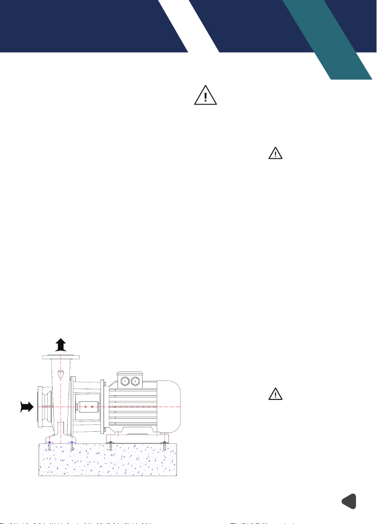
6. Assembly/Installation 7
6.1. Installation 7
6.2. Fixing (Securing) Of Pump Group 7
6.3. Piping 7
6.4. Motor Connection 8
7. Commissioning, Start up and Operating 9
7.1. Preparations Before Start up 9
7.2. Checking The Direction of Rotation 9
7.3. Start up Procedure 9
7.4. Shut Down Procedure 10
8. Maintenance 10
8.1. The Checks During the Operation 10
8.2. Service 11
8.3. Spare Parts 11
9. Noise Level and Vibration 11
10. Disassembly, Repair and Reassembly 11
11. Possible Failures, Causes, Solutions 13
12. Pump Dimensions Table 14
13. Tightening Torques 20
14. Forces And Moments at The Pump Flanges 20
15. Sample Plumbing 22
16. NMM Sectional Drawing and Part List 23
17. NMM Drawing for Dismantling 25
18. NMM Series MEI Values Table 27
INTRODUCTION
• This manual contains instructions for the installation,
operation and maintenance ofthe NMM type horizontal
single stage, non-self priming centrifugal pumps of
MAS DAF MAKINA SANAYI A.Ş.
• Please read carefully this manual and apply all the
instructions to operate pumps without problems.
Pumps shall be used for their intended duties. In this
manual, there are information on operating
conditions, installation, starting-up, settings and main
controls of pumps.
• These operating and maintenance instructions
contain MAS DAF MAKINA SANAYI A.Ş. ` s suggestions.
The special operating and maintenance information of
the plumbing that a pump is fitted to is not considered
in these instructions. This information must be given
by the plumbing constructors only.
• Please refer to instructions of plumbing constructors.
• Please pay attention to the warnings in this manual
and ensure that it is read before the installation-start
up process. MAS DAF MAKINA SANAYI A.Ş. is not
responsible for the accidents resulting from negligence.
• If you cannot find an answer to your questions in this
manual, it is suggested that you contact MAS DAF
MAKINA SANAYI A.Ş. Please inform us about the rated
value and especially the serial number of the pump
when you get in contact for help.
• The safety instructions in this manual cover the current
national accident protection regulations. Beside all of
these, an operation, work and safety measure imposed
by the costumer has to be applied.
The Signs Used in This Operation Manual
Read the instructions carefully in this
operating manual and keep it for your
future reference.
Warning sign against the electrical risks
Sign for the operator’s safety
1. IMPORTANT SAFETY PRECAUTIONS
In order to minimize the accidents during the mounting
and putting into service of the pump, the following rules
have to be applied:
1. Do not work without taking safety measures
relevant to equipment. Cable, mask and safety band
must be used when necessary.
2. Be sure there is adequate amount of oxygen and
there is no toxic gaseous around
3. Before using welding or any electrical equipment
make sure that there is no risk of explosion.
4. Check the cleanliness of the area to take care of your
help. (Dust, smoke, etc.)
5. Do keep in mind that there is a risk of having
accidents related to electricity
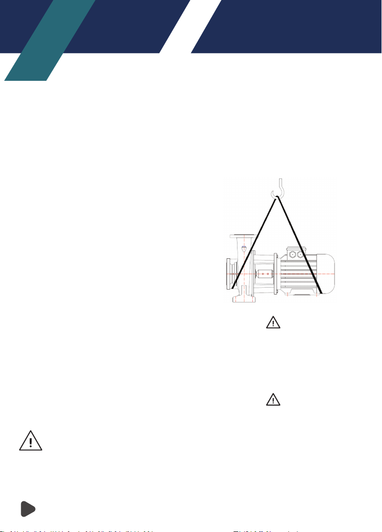
6. Do not lift the pump before you check the transport
equipment.
7. Be sure you have a by-pass line
8. Use helmet, eye glasses and protective shoes for
your safety
9. Place a protective barrier around the pump within
the necessary safety area
10. Dust, liquids and gaseous that may cause overheat-
ing, short circuit, corrosion and fire must be kept away
from the pump unit.
11. By checking the noise level of the pump unit,
necessary measures to avoid noisy operation of the
pump that can have harmful effects on the personnel
and environment.
12.Be careful about the direction of transport and
storage.
13.Cover appropriately the moving parts to avoid
possible injury of the personnel. Mount the coupling
guard and belting before starting-up the pump
14. All the electrical and electronic applications must be
performed by authorized person conforming
EN60204-1 and /or domestic instructions.
15. Protect the electrical equipment and motor against
overloading
16.If flammable and explosive liquids are pumped,
ground connection of electricity should be carried out
properly
17. Do not expose the pump unit to sudden temperature
variations
18.All personnel who work with the waste water
system need to be vaccinated in case of contagious
diseases.
19.If the pump contains hazardous liquids, one must
use protective helmet against the risk of splatter. One
also must accumulate the liquid in a proper container
against any risk of leakage.
All Other Health and Safety Rules, Laws and
Regulations Must Be Applied
2. GENERAL
2.1. Definition of Pump and Usage Areas
NMM series pumps are single stage, close coupled
volute type pumps. They are used in
• Water networks and pressurization facilities
• Irrigation, sprinkling and drainage systems
• Filling –Draining of tanks and reservoirs
• Hot and Cold water circulation in heating and cooling
systems.
• Condense water pumping
• Water circulations in pools
• Health purification facilities
• Industrial and social facilities
• Fresh and sea water pumping in ships.
They shall be used to pressurize liquids (up to 120°C)
which are clean or mildly impure, non abrasive, and not
containing large solid particles or fiber.
CAUTION
Please contact MAS DAF MAKINA SANAYI A.Ş. for
liquids that have different chemical and physical
specifications.
NMM type centrifugal pumps are comprised of 29
types which conform to DIN 24255 (EN 733) standards.
Technical specifications of NMM type pumps
Suction Flange: DN 50 – DN 150
Discharge Flange: DN 32 – DN 125
Operating Pressure: 10 Bar
Operating Temperature: -25 – 120°C
Capacity: 5 – 400 m³ / h
Hm: 4 - 110 m
Speed: 1450 – 2900 RPM
Product Information as per Regulation No. 547/2012 (for
Water Pumps with a Maximum Shaft Power of 150 kW)
Implementing "Ecodesign" Directive 2009/125/EC
Minimum Efficiency Index for MAS NMM Pump Series is
shown on the pump label.
MEI values of MAS NMM Pump Series are shown on the
pump characteristic curves.
Minimum Efficiency Index for MAS NMM Pump Series;
Minimum 0.4. (MEI≥0,4)
Efficiency values of the pump characteristic curves, which
are cut diameter, are expressed in %.
NMM Series water pumps, the pump efficiency can be
achieved more than fix speed in case of variable speed
control.
More information about the Ecodesign can be reached at
www.europump.org
Figure 1: Pump Label
2.2. Performance Information
Actual performance of the pump can be obtained from
the order page and/or from the test report. This
information is given on the pump label.
The performance curves given in the catalog are valid
for water whose density and viscosity are ρ=1 kg/dm3
and ν=1 cst. respectively. For those liquids whose
densities and viscosities are different from those of
water, please consult with MAS DAF MAKINA SANAYI
A.Ş. since the performance curves varywith density and
viscosity
CAUTION
Do not operate the pump with a motor that has a
different power except for the given catalog and
label values.
The pump is not to be operated at off-design point
given in the order and supplied from the firm.
It is necessary to ensure that the instructions are
obeyed for the safe running of the pump.
2.3. Warranty Conditions
The entire products in ourselling program are warranted
by MAS DAF MAKINA SANAYİ A.Ş.