4
NOTE:- All positional descriptions such as left, right, front, rear,
above and below refer to those places as seen by the operator
when standing behind the handle of the mower in its normal
grass-cutting orientation. Please note that these instructions
are to be read in conjunction with the Owner’s Manual for the
mower and the Engine Manufacturer’s Operator’s Manual for
the engine.
ALWAYS USE GENUINE MASPORT SPARE PARTS
Controls
ENGINE CONTROLS
All engines have a throttle control to allow the engine speed to be
varied as desired. This control does not operate the choke or stop
switch on the engine. See the engine manual for information on using
the choke and stop controls. Moving the throttle to the slow position
will disengage the centrifugal engine clutch and stop rotation of the
cutting cylinder. Some mowers are fitted with an Operator Presence
Control (OPC) that allows the engine to run only while the OPC bail (a
bar or hand-grips in front of the handle crossbar) is held against the
handle. If the operator releases the bail, the engine stops immediately.
Throttle Control Adjustment
A B
With the engine running, move the throttle lever through its full travel
range. In the slow position, the engine should run at idling speed and
the cutting cylinder should be stationary. At the fast end of the range
the engine should be running at a speed that will require a brisk walk
to keep up with the mower. If one end or the other of the lever travel
does not produce the required result, simply release the clamp that
holds the cable outer sleeve (on the engine), move the sleeve a few
millimetres under the clamp and re-tighten it. Test again and adjust as
necessary.
CAUTION. Do not run the engine for more than a few seconds
with the cylinder rotating if the mower is not cutting grass.
Grass lubricates the cutting edges, preventing overheating and
premature wear.
Throttle Control Replacement
If the control is a type A shown above, simply detach the control box
from the handle, note where the cable ties are fitted and cut them.
After releasing the cable clamp screw on the engine, the new cable
can be fitted and held in place with new cable ties. Clamp the control
box onto the handle, refit the clamp screw and adjust the cable
position as detailed above.
To gain access to the control box for type B throttle controls, remove
the four screws under the throttle mount that hold the two halves of
the mount onto the handle. The top throttle mount can then be lifted
clear of the handle. Remove the M6x60 screw that fixes the control
box to the top mount, note the cable tie positions and cut the cable
ties. After the clamp screw on the engine has been removed, the
throttle wire can be disengaged from the carburettor lever. The old
control box can then be withdrawn from the top mount. Reverse this
procedure to fit the new throttle control. Take care not to over-tighten
the M6x60 screw that holds the control box to the top mount as this
would make movement of the throttle lever very stiff. After fitting the
cable wire into the carburettor lever, re-assemble the two halves of the
throttle mount onto the handle, fit new cable ties, replace the clamp
screw and adjust the throttle cable sleeve position under the clamp as
described above to give correct operation of the engine.
OPC Control Adjustment
There are no adjustments provided on this control as it is a safety
feature required in the Northern Hemisphere that might then be over-
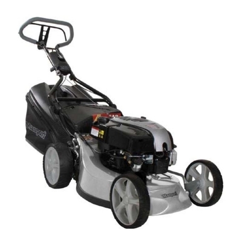
ridden. When the OPC bail (see the illustrations above) is held against
the handle, the engine ignition can function and the mower can be
started. When the bail is released, the primary winding of the ignition
coil is shorted out, thus quenching the ignition spark and stopping the
engine. If the OPC bail has been damaged and twisted out of shape,
the bail may contact the handle before the ignition has been ‘switched
on’. This is rare, but straightening of the bail can provide a little extra
control wire travel to correct the fault.
PROPULSION CONTROLS
Drive Clutch
The mower drive system is engaged by using the SP (Self Propulsion)
bail. See the illustrations on the left. Of course, the drive clutch will not
drive the roller unless the engine clutch is engaged and the cutting
reel is rotating. The drive clutch is mounted inside the chaincase
cover. Both clutches are designed to be fully engaged or fully
released. Any attempt to reduced travel speed by only partially
engaging the clutches will lead to overheating of the clutch
linings, causing serious damage. It is important that the SP bail
cable is adjusted to the correct length to provide the necessary clutch
engagement pressure.
Drive Clutch Cable Adjustment
Step 1. Confirm that the cable inner wire will move at least 26 mm
when the SP bail (see to the left) is moved from the clutch disengaged
(open) position to the engaged (closed) position against the handle.
Adjust the contour of the bail slightly if necessary to achieve this wire
stroke.
Step 2. Pull the mower backward toward you while gradually closing
the SP bail, and note the position of the bail when extra resistance to
backward movement indicates that the drive clutch is just engaging.
This extra resistance should occur when the SP bail is about half way
between open and closed.
Step 3. If the engagement point is incorrect, adjust it by rotating the
thumb-wheel on the anchor block at the top of the drive clutch cable
sleeve. Rotating the wheel clockwise will move the clutch engagement
point nearer to the bail closed position, and anti-clockwise will move it
toward the bail open position.
Step 4. Verify that the adjustment is correct by field testing the mower.
It should be possible to close the bail against the handle without the
need for excessive pressure, and there must be no sign of drive clutch
slippage.
Step 5. Repeat this adjustment after 150 hours use of the mower or
at any time if the mower drive seems to be slipping.
NOTE, If the available adjustment on the thumb-wheel is insufficient to
achieve correct operation, another adjustment point is available on the
drive clutch itself. The draw bolt through the centre of the clutch can
be tightened to compensate for clutch lining wear
