Massive Audio P1000.1 pro series User manual

2005 Massive Audio Inc.
Printed in the U.S.A.
MASSIVE
Massive Audio Inc.
2261 S. Atlantic Blvd.
City of Commerce, CA 90040 U.S.A.
www.massiveaudio.com
1000.11000.1PP
500.1500.1PP
1500.11500.1PP
3000.13000.1PP
C
Pro Series AMPLIFIERSPro Series AMPLIFIERS
V.012005

Congratulations!
And thank you for purchasing a “Massive Audio” Pro-Series class D
amplifier for your car audio system. You now own an amplifier of
uncompromising design and engineering incorporating the latest
advances in circuitry. This handcrafted anplifier is designed to deliver
the demands of serious sound competitors. You will soon discover that
Pro-Sereis amplifiers display a fine balance between high quality,
performance and reliability; all proven qualities of “Massive Audio”
products.
“Massive Audio” amplifiers are the result of American Craftsmanship
using only the highest quality components and quality control
standards. In order to provide you with many years of listening
pleasure, we recommend you to have your new amplifier installed by
an Authorized “Massive Audio Dealer.” This will ensure the proper
installation of your product, and will also increase the length of your
warranty to TWO YEARS.
(Please see the warranty section of for more details.)
Please take a moment to thoroughly read this manual to ensure that you
get the maximum benefit from this new addition to your car audio
system. When installed properly, this unit will provide years of
trouble-free performance.
Should your amplifier ever need service or replacement due to theft,
please record the following information, which will help protect your
investment.
Model #: _______________________________________
Dealer’s Name: ___________________________________
Date of Purchase: __________________________________
Installation Shop and Date:__________________________
INTRODUCTION: DESIGN FEATURES
2
RInput sensitivity low level: 120mVrms ~ 5.0 Vrms
RFrequency response: 8 Hz - 180 Hz
RVariable Lowpass: 40 - 180 Hz / 18dB
RBass Boost 0 - 12 dB @ 45 Hz
RShort Circuit, Thermal, reverse voltage
and over voltage protection.
RAll models linkable with single RCA for easy
upgrade
RN-Channel Circuit for high-efficiency
RHeavy duty power supply.
RIlluminated logo.
RHeavy duty aluminum heatsink.
RProprietary “Bass Kompressor” circuitry
provides low- frequency enhancement
RDesigned and engineered in U.S.A.
ROptional remote gain control
R
R

Amplifier Functions
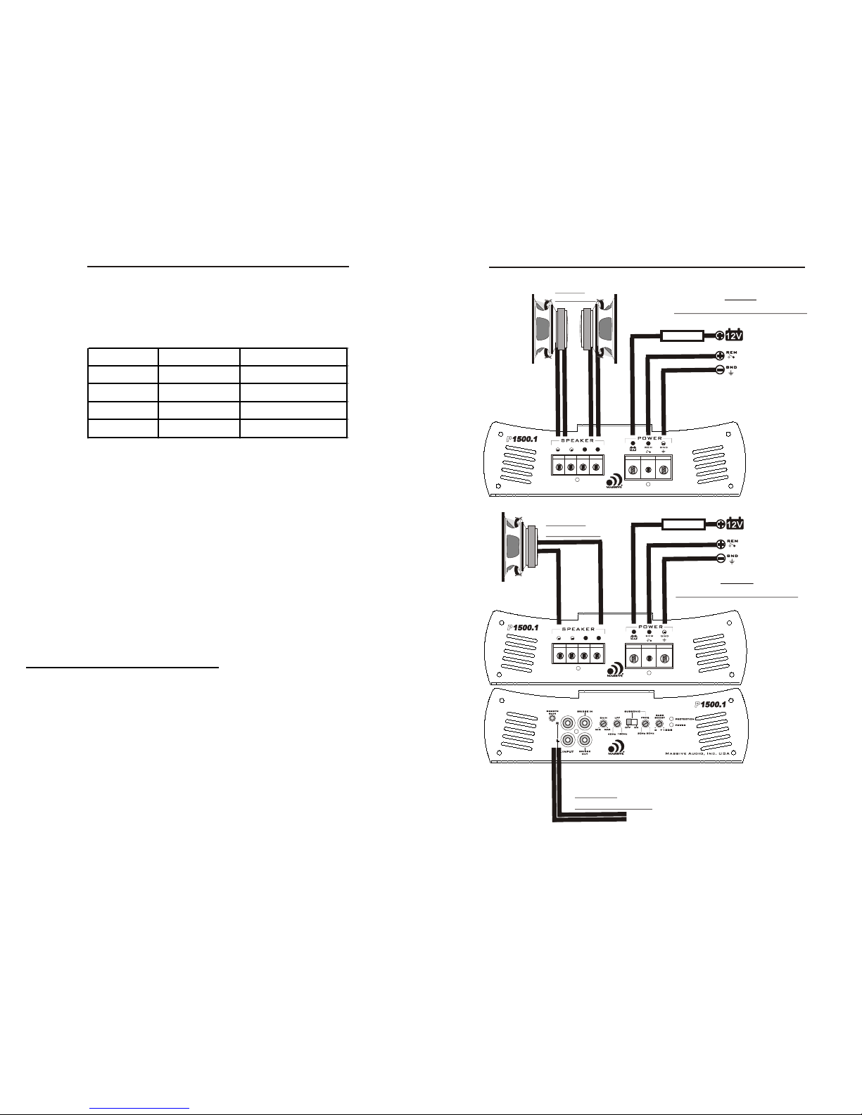
1. Speaker connection
· Never connect the speaker cables with the chassis ground. This could destroy
your amplifier.
· Check that your speakers are connected correctly which means plus to plus and minus
to minus
We recommend speaker cable from 2.5 mm² and up. Other connection variations are shown
attached.
2. BATT+
Battery + (plus) terminal. The + (plus) 12 Volt power cable must be connected with a fuse on
the battery + (plus) terminal. We recommend a 100 ampere ANL fuse and a copper cable with
a thickness of 25 mm² for cable length up to 5 metres.
3. REM
Remote terminal. The remote cable must be connected with the radio automatic antenna
terminal so that the amplifier will switch on and off automatically with the radio. If there are
2 or more amplifiers connected to this antenna terminal it might be necessary to add an
additional relay. Please consult your dealer.
4. GND
Chassis ground-terminal. The chassis ground cable must be connected very tight on a
nearby massive and electric conductive place.
5. Gain
Gain control regulates the sensitivity of the amplifier to match the signal output voltage of
your source unit.
The Gain control is not intended for volume adjustment.
Use high quality CD music and increase the volume of your source unit to 75%.
Position the Gain at the minimum and then slowly increase Gain (clockwise).
Stop at the first sign of distortion, then lower the Gain a little ( counter clockwise) to achieve
clear undistorted music at the maximum level.
6. Remote Bass Level Control ( Optional )
When using the Remote Bass Level Control you have the ability to control the level of the
subs from the driver seat.
7. RCA audio-input
These RCA inputs are to be connected with your radio preamp RCA outputs. Please use
RCA cables made for car audio, otherwise there could be disturbances. Keep these cables
as short as possible. To avoid disturbances from your car electronics, install the RCA cables
not to close from existing car cables. If your radio has only one preamp output please use
a suitable Y-RCA adaptor. If your radio has only speaker outputs you must use a
HIGH-LOW-LEVEL adaptor.
8.Fuse (P 500.1 only)
To protect the amplifier when current drawn is more than rated.
Never replace a fuse with a higher amp fuse.
Never replace a burnt fuse before checking the system for cause of malfunction.
Never bridge a fuse.
.
4
9. Bridge in
This RCA jack receives the signal sent from the master amplifier when this amplifier is bridged as
slave. DO NOT use Input Jacks when the amplifier is set as slave. All the level and functions will
be adjusted along with the master amplifier.
10. Bridge out
This RCA output signal is sent to other Pro-Series amplifiers in an bridged configuration.
11. Low Pass
To filter out the high frequency and only produce low frequency with 24 dB filter (12dB P 500.1)
to insure high quality solid bass reproduction.
12. Subsonic Switch ( not available on P 500.1)
When switched on it will filter unwanted low frequency with a 24 dB filter. This feature will
increase the power handling of your woofers.
Usually all frequencies below the enclosure tunning have increased impedance which results in
increasing the voice coil temperature.
13. Subsonic Frequency ( not available on P 500.1)
When the subsonic switch is on, it will adjust the cut off frequency filter from 20 Hz - 50 Hz
14.Bass Boost
This function will increase the bass boost level from 0 to 12 dB with center frequency at 45 Hz.
15. Power-LED
Indicates the amplifier is switched on. It will flash when there is a mal function.
16.Protection-LED
Indicated if the amplifier is in protection or other malfunction.
1000.11000.1PP
1500.11500.1PP
3000.13000.1PP
1
1
5
5
6
6
7
7
8
9
9
11
11
1
2
1
3
1
4
1
5
1
5
1
6
1
6
1
0
2
2
3
3
4
4

We recommend to have the installation done by an Authorized Massive Audio, Dealer.
Required Power, Ground Connection and proper external fuse as indicated below:
We recommend a fuse to be installed within 16 inches of the battery.
The Ground Wire should be connected directly to the chassis of your vehicle with a
metal to metal ground point connection.
The amplifier must be securely mounted to a solid, dry and low vibration surface in the
trunk or passenger area.
Position the amplifier in an area with sufficient air flow to insure proper heat dissipation.
Position the amplifier for an easy access to the input-setting controls.
Install all amplifier cables as far as possible from car electrical cables. i.e. The car
ignition cable.
Pre Installation
6
Wiring Configuration
FUSEFUSE
FUSEFUSE
1 OHM
MINIMUM
2 OHM
MINIMUM
5V max
Signal Input
TWO
SPEAKERS MONO
ONE
SPEAKER MONO
Important:
* When bridging two amplifiers, connect cables as shown in the bridge figure. (Page 8)
* When bridging two amplifiers you must use the same model amplifier.
* Please make sure the negative output terminal of two amplifiers are connected with the same
gauge cable as the positive terminal being used.
* DO NOT connect any signal to the input RCA jacks when bridged as slave unit.
* The LPF, Input Level, and remote functions will we disabled on slave amplifier when bridged.
* The Input Level and the LFP frequency of the slave amplifier will be adjusted along with the
master amplifier.
Model Fuse Wire
P 500.1 40 AMP 6 Gauge
P 1000.1 60 AMP 4 Gauge
P 1500.1 100 AMP 2 to 4 Gauge
P 3000.1 200 AMP 0 Gauge

SPECIFICATIONS
160 W
280 W
420 W
500 W
8Hz - 185Hz
16Hz - 139Hz
>92 dB
N/A
67 Kohm
85%
>100
P 500.1P 500.1
0.6 A
60A
1 Ohm
40
2.6 x 8.7 x 9
66 x 220 x 229
0.2 - 5V
P 1500.1P 1500.1
600 W
950 W
1250 W
1500 W
8Hz - 180Hz
16Hz - 135 Hz
> 100 dB
YES
67 Kohm
>120
0.2 - 5V
82%
1.2A
120A
1 Ohm
100
2.6 x 8.7 x 16.9
66 x 220 x 429
P1000.1P1000.1
320 W
540 W
880 W
1000 W
8Hz - 180Hz
16Hz - 135 Hz
> 100 dB
YES
67 Kohm
0.2 - 5V
>110
82%
0.8A
100A
1 Ohm
60
2.6 x 8.7 x 13
66 x 220 x 329 66 x 220 x 882
8Hz - 180Hz
16Hz - 135 Hz
> 100 dB
YES
67 Kohm
>120
0.2 - 5V
82%
2.2A
240A
2 Ohm
200
2.6 x 8.7 x 34.7
P 3000.1P 3000.1
1800 W
2680 W
N/A
3000 W
RMS @ 4 Ohm (<1% distortion)
RMS @ 2 Ohm (<1% distortion)
RMS @ 1 Ohm (<1% distortion)
Maximum Power @ 14.4 VDC
Frequency Response @ -3 dB
Frequency Response @ -1 dB
S/N Ratio ( A. Wtg )1 Watt reff.
Bass Boost @ 45 Hz 12 dB
Input Impedance
Input Sensitivity
Damping 100 Hz @ 4 Ohms
Efficiency
Idle Current
Max Peak Current
Minimum Impendence
Required External Fuse
Dimensions (H x W x L) Inches
Dimensions (H x W x L) Metric(mm)
ModelModel
OPTIONAL
REMOTE CONTROL
FUSEFUSE
FUSEFUSE
2 OHM
MINIMUM
4.5V max
Signal Input
AMP #1
MASTER
AMP #1
MASTER
AMP #2
SLAVE
AMP #2
SLAVE
TWO AMPLIFIERS LINKED TO ONE CHANEL TWO AMPLIFIERS LINKED TO ONE CHANEL
8

Troubles Shooting
Malfunction Should Check
Power LED doesn`t light up check all fuses on the amplifier
check main fuse near the battery
check plus and minus battery cables
check remote voltage
Power LED is on but no sound check volume control on the radio
check GAIN regulator on the amplifier
check RCA cables and connections
check speaker cables and connections
Bass response is low one speaker cable could be disconnected
the bass control on the radio is set on low
an active crossover unit is adjusted wrong
The amplifier switches bad chassis ground connection to the amplifier
On and Off cable terminals and battery terminals are oxidated
low voltage from the battery
remote wire is not connected right
One channel has no function check RCA connections of this channel
check speaker connection of this channel
balance regulator to the radio is not set in the middle
check speakers for this channel
For additional questions please contact your authorized Massive Audio, dealer.
Massive Audio, Inc. warrants all manufactured amplifier
products to be free from defect in material and workmanship
for a period not to exceed TWO YEARS* from the date of
original purchase when installed by an authorized “Massive
Audio” dealer. Units that are not installed by an authorized
“Massive Audio” dealer maintain a warranty not to exceed 90
days from the original purchase date by the original purchaser.
PrOducts that displays abuse such as power deficiency, over
driving the amplifier or clipping the input require
purchase of new PCB for replacement.
“Massive Audio” obligations under this warranty are limited to
repairing or replacing, at its own sole option, any such
defective products. This warranty does not apply to equipment
that has been damaged by accident, negligence, or
misapplication or has been altered or modified in anyway.
This warranty applies only to the original purchaser who must
have properly registered the product within 10 days of
purchase.
Except as provided herein, Massive Audio, Inc. makes no warranties or
representations, express or implied, including any warranty implied by
law, whether for merchantability or fitness for a particular purpose and
shall be effective only for the period that this express warranty is
effective. SEE THE WARRANTY REGISTRATION CARD TO
ADDITIONAL INFORMATION.
10
WARRANTY
This manual suits for next models
3
Table of contents
Other Massive Audio Car Amplifier manuals

Massive Audio
Massive Audio Primo Series User manual

Massive Audio
Massive Audio BX2 User manual

Massive Audio
Massive Audio Volt V500.2 User manual

Massive Audio
Massive Audio HD 8004 User manual

Massive Audio
Massive Audio D 200X User manual

Massive Audio
Massive Audio D2500.1 block series User manual

Massive Audio
Massive Audio D-Block Series D 4000.2 User manual

Massive Audio
Massive Audio P400.4 pro series User manual

Massive Audio
Massive Audio N2 User manual

Massive Audio
Massive Audio N2 User manual