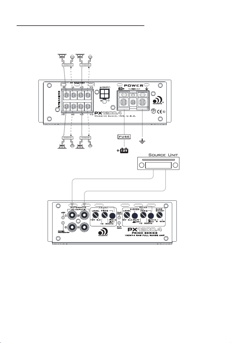
5. RCA INPUT / AUTO HI-LOW LINE CONVERTOR
These RCA input jacks connect with your source unit RCA Low Level outputs
or via optional adapter with your source unit speaker high level outputs. The use
of High quality twisted pair car audio cables is recommended to mind possibility
of disturbance the audio signal.
Amplifier Functions
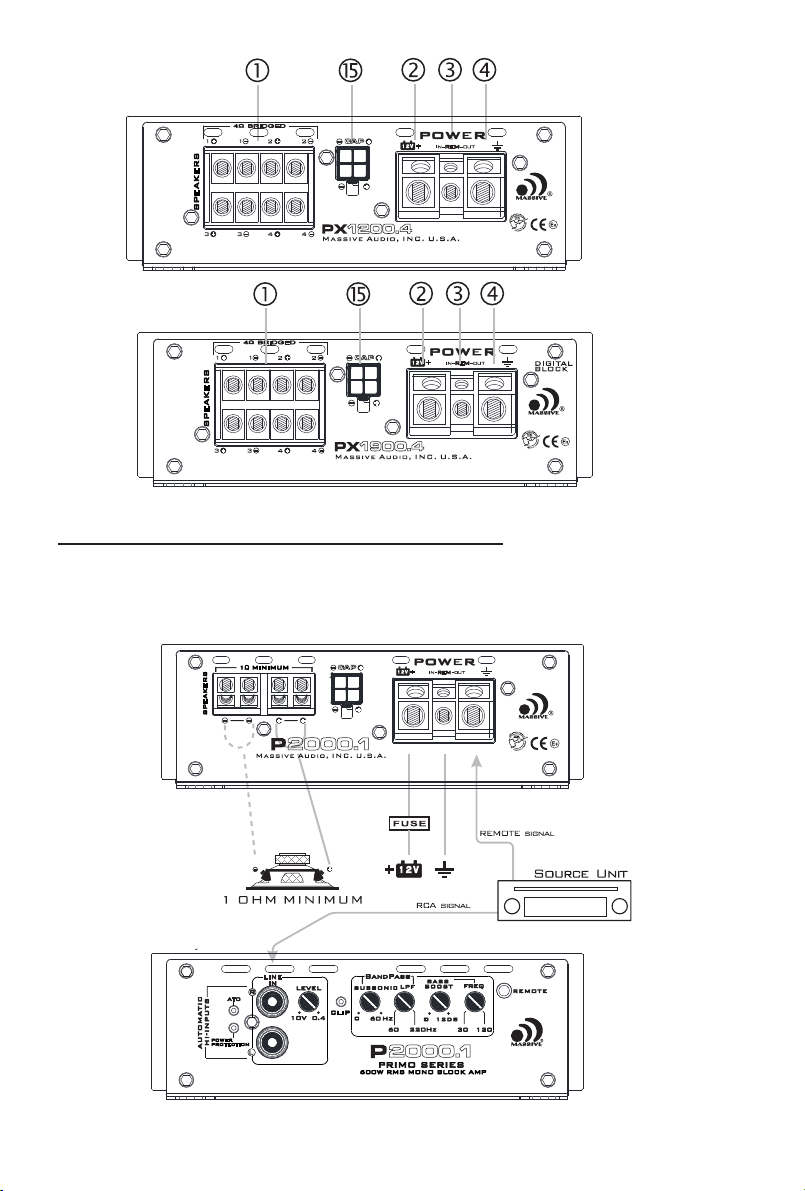
1. Speakers
Connect speakers/subwoofers to these terminals. Be sure to check wire for
proper polarity. never connect the speaker cables to chassis ground.
2. +12 Volt Power
Connect this terminal through a fuse or circuit breaker to the positive terminal
of the vehicle battery or the positive terminal of an isolated audio system battery.
3. Auto sensing Turn On Function / REM OUT(HI-INPUTS)
When use HI-INPUT, the amp can detect the DC OFFSET from the high level input
signal to auto turn on/off. When the amp turns on, the REM terminal will output
+12V DC to control the other device turn on/off.
REM IN: When use Low level input, the Amp REM IN should be connected to the
REM OUT of the Source Unit. The head unit controls the amp turn on/off.
4. GND
Connect this cable directly to the frame of the vehicle. make sure the metal
frame has been stripped of all paint down to the bare metal.
Use the shortest distance possible. It is always a good idea to replace the
factory ground at this time with a larger cable equal to the new directly to the
vehicle battery ground terminal or any other factory ground points.
6. Remote(Mono Blocks)
Connect the remote controller to control the subwoofer amplifier volume
from the driver seat location, For ease of adjustment during playing.
7. Gain-Level Control
The Gain control will match the amplifiers sensitivity to the source units signal
voltage. The Operating range is 10V to 400mV. This is NOT a volume control!
8. Low Pass Filter Control(Mono block)
This control is used to select the desired low pass x-over frequency. The
frequency can be adjusted from 6OHz to 220Hz for all bass mono models.
9. Subsonic Filter Control(Mono block)
This control can filted out unwanted low frequency from OHz(off) to 60Hz.
This function will increase the power handling of your woofers.
10. Bass Boost Level knob(Mono block)
This control adjust the boost level of the bassboost center frequency. It can
be adjusted from 0 to 12dB. Combining with bassbootst frequency, You can
accurately match the amplifier performance to woofer response.
11. Bass Boost FREQ knob(Mono block)
This control the boosted center frequency. The frequency can be adjusted
from 30Hz to 120Hz according to your car audio system performance. (Eg. When
you adjust this knob to 50Hz, Amplifier will boost the frequency around 50Hz.)
This function should be adjusted combining with bassboost level tuning.
12. X-over mode (full range)
This switch works together with the FREQ to adjust the operating frequency range
of the amp. When switch to LPF or HPF, The corresponding filter can adjust the operating
frequency range between 10Hz to 300Hz ( or 100Hz to 3KHz) .When pushing the
subwoofer, Please switch to LPF mode; When pushing small caliber full frequency
speaker, Middle and high frequency loudspeaker, Please switch to HPF mode. When
3