Master cool MCP44 User manual

1
10/2013 72582 Printed in China
To Buy: Visit www.sylvane.com or call (800) 934-9194
Product Support: Contact MasterCool at 800-643-8341

2
MasterCool® MCP44 Evaporative Window Cooler
Operating and Installation Instructions
Congratulations on your purchase of the MasterCool® MCP44 plastic evaporative cooler. This unit is
manufactured with the intent of offering you years of reliable, efficient cooling.
NOTE: READ THESE INSTRUCTIONS BEFORE INSTALLING THE COOLER. Follow the installation instructions in
this manual carefully. Varying from them may create safety concerns and will void the warranty.
Table of Contents
Safety Instructions.................................................................................................................................................2
Note About Evaporative Coolers...........................................................................................................................3
Features of the MasterCool® MCP44 Window Cooler .........................................................................................3
Installation Procedures .........................................................................................................................................4
Cooler Assembly ..................................................................................................................................................4
Installation in Window ........................................................................................................................................5
Installation in Wall...............................................................................................................................................5
Water Connection, Water Pump and Lines, Overflow Drain, Water Level ........................................................6
Electrical System & Specifications......................................................................................................................7
Plug-in Thermostat Usage..................................................................................................................................7
Optional Purge Pump .........................................................................................................................................7
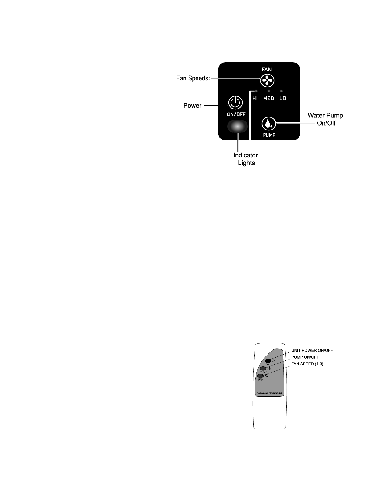
Operating Instructions ..........................................................................................................................................8
User Servicing Instructions............................................................................................................................... 9
Annual Maintenance ........................................................................................................................................ 9
Winterization ..................................................................................................................................................11
Cooler Diagram and Parts List.............................................................................................................................12
Troubleshooting ............................................................................................................................................. 13
Warranty ............................................................................................................................................................14
Español Manual………………………………………………..……………………….……………………….. 15
Maintenance Log …………………………………………………………………….……..………………….. 28
Safety Instructions
1. Use only with 110V 60 Hz single phase grounded outlet.
2.
Ensure cooler is turned OFF and UNPLUGGED before installing, servicing or cleaning
the unit.
3.
Do not operate unit with damaged cord or plug, or with any other damaged or
missing parts.
4. o not run cord under carpeting. Do not cover cord with throw rugs, runners, or
D
similar coverings. Do not route cord under furniture or appliances. Arrange cord
away from traffic area and where it will not be tripped over.
5. Do not operate cooler with the rear media guard removed.
6. Do not use an extension cord to operate cooler.
7. Do not use an adapter to convert the three pin connector for use in an ungrounded
2 prong outlet.
8. DO NOT use with a solid state speed control device. Violation of this could cause fire
or electrical shock.
9. Do not alter or modify this cooler.
10. Repairs or replacement of electrical components should only be carried out by
qualified electricians.
11. Do not allow children to install, service, or operate the cooler.

3
Note About Evaporative Coolers:
Ventilation:
Unlike traditional air conditioners, evaporative
coolers require an open ventilation system, not
a closed system. Both a fresh air source and an
exhaust opening are required to provide
correct air flow. Typically, a partially opened
window or door in each room where cooling is
desired will create correct airflow for optimum
effectiveness of an evaporative cooler.
NOTE: For best results, open windows/doors
should not be on the windward side on the
house.
Water bleed or purge:
Evaporative Coolers require a continuous supply of water to keep the media saturated for maximum cooling.
Water pumped into the cooler must be removed from the unit to ensure mineral and bacteria build-up do not
occur. This can occur with a gravity-fed steady bleed off stream or a timed purge system via a pump.
CAUTION: Water expelled from the cooler must be routed away from any areas that could do damage to
foundations or other vulnerable areas.
NOTE: Drawings in this manual are for illustrative purposes only and may reflect slight differences depending
on design level and configuration.
Features of the MasterCool® MCP44 Window Cooler
This cooler’s housing and frame are made of heavy-duty U-V resistant plastic to provide a light weight, easily
installable cooler. The unit is constructed in two basic sections to facilitate quick installation into traditional
sash windows or slider windows.
The high-efficiency rigid media offers superior cooling over other types of evaporative coolers.

4
NOTE: BEFORE INSTALLING UNIT, TAKE A MOMENT TO RECORD THE SERIAL NUMBER AND WRITE IT ON THE
MANUAL COVER IN THE SPACE PROVIDED.
INSTALLATION PROCEDURES
WARNING: Do not connect electrical power to the unit until the installation is completed.
The MasterCool MCP44 cooler can be installed in a sash-style or a slider- style window.
Alternatively, this unit is approved for in-wall installations.
In all installations, the following clearances are required:
Width: 22”; Height: 22” 4” clearance above the exterior cabinet is needed for maintenance.
NOTE: Ensure the location selected for installing the unit is strong enough to support the unit and will accept
the mounting hardware. The operating weight of the cooler is 93 pounds.
NOTE: A minimum of two people is required for installation.
Parts Included:
Cooler Unit
Mounting brackets (4)
Accordion spacers (2) Hardware kit
Tools & Materials Required:
Drill (power or cordless)
Assorted drill bits (for drilling pilot holes for mounting hardware)
Adjustable Wrench
Phillips Head Screwdriver
Silicone or all-weather caulk for sealing infill panel to window frame
Length of ¼” copper or plastic tubing
Sillcock valve
Bubble level
spacer material (as required)
Cooler Assembly
Remove unit from box. Verify that all parts are included.
1. Remove all packing materials.
CALL 1-800-643-8341 IF YOU FIND PARTS MISSING OR HAVE ANY QUESTIONS
2. With the unit in an upright position, remove 4 screws holding the back media guard, separate front and
back sections. Pull the fan assembly forward (about 6”) until it is fully engaged with the mating part and
secure in place using the 12 supplied screws. Verify that assembly is secure to prevent vibration between
the two sections.

5
Installation in Window
2. Closing the window may help hold the unit in place during the following steps –Push the unit into the window
until the bottom is flush with the outside wall or spacer (not supplied) as shown in the illustration.
3. Make sure unit is level. From the interior, locate the two tracks on the bottom of the fan assembly. Drill
pilot holes as necessary and install the two window sill brackets as shown in illustration.
4. Secure the top of the fan housing to the window frame with two additional brackets and screws.
5. From the outside, secure the unit to the exterior wall (or spacer) with two screws at the base of the back
cover (as shown in illustration.) Complete the installation of the exterior portion with two screws at the
top of the back media guard.
6. With the unit now installed in the window, attach one accordion spacer to each side of the fan assembly
using the adhesive backed edges. Short screws(not included) can be used for a more secure installation.
(Make sure screws do not interfere with fan blade)
7. Once accordion spacers are installed, seal any gaps around the units with silicone or all weather caulk.
Installation in Wall
This cooler is approved for in-wall installation. Contact a licensed contractor for having the cooler installed in an
outside wall.
1. Remove screen and make sure window is
opened to its maximum height. From the
exterior of the window, slide the fan assembly
section into the window. Have the person on
the interior adjust the exact placement of the
unit for aesthetics and correct lengths of the
two accordion spacers (included).
Note: After identifying the position for
installation, place a bubble level on top of the
unit and make adjustments to ensure the unit
will be level when installation is complete. It
is recommended to verify unit is level at
various points during installation.

6
Water Connection
NOTE: A standard sillcock with water valve attached (locally available) will
be required to connect the water supply to the cooler.
1.Steady water supply is required for operation of the cooler. If taking water
from an external water faucet, install a sillcock and shutoff valve.
2.Install plastic or copper line to sillcock and connect it to the float valve.
Water Pump and Lines
A self-contained water pump continuously
circulates water through the water distribution
system and over the media.
The pump and water lines are shipped unconnected.
Connect the Water Lines
1. Locate the black water line snapped into plastic
keepers inside the unit.
2. Attach the bottom end of the main water line to
the pump inlet.
3. Remove the nipple inserted into the end of the
overflow line. Push overflow hose into one of the
slots in the sides of the overflow drain fitting.
4. Reinsert the nipple into the overflow line.
5. Attach the top of the hose to the water distribution
tray.
6. Ensure there are no kinks in the water lines after
completion.
Overflow Drain
1. Slide the rubber washer over the overflow fitting and push through the hole in the bottom of the cooler from
the top side.
2. Secure the drain from beneath the pan with the Lock Nut.
Make sure the rubber washer does not twist while tightening,
which could cause it to leak. DO NOT OVERTIGHTEN.
3. If leakage occurs after reservoir is full, retighten the overflow fitting until
leaking stops. A small amount of silicone caulk may be used if necessary.
4. Attach a drain hose to the bottom of the fitting if necessary.
Water Level
Two inches of water
should be maintained
in the bottom of the cooler to ensure sufficient water
for correct operation of the cooler.
The float is factory-installed to maintain a 2 inch
level of water, but may require adjustment if shipping
or installation has caused the setting to shift.

7
Electrical System
The electrical system does not require general maintenance. The following wiring diagram is supplied for
reference only.
ELECTRICAL SPECIFICATIONS OF MCP44 COOLERS
MCP44
Fan Motor: 120 V; 2.8 Amps
Main Pump: 120 V; 0 .9 Amps
If Optional PURGE PUMP is installed
Additional 0.9 Amps
Plug-In Thermostat Usage
The MCP44 can be controlled by a plug-in programmable thermostat. These thermostats are locally available,
and enable precise timing and temperature control via an electronic thermostat that plugs into a 110 volt outlet.
To use such a device with the MCP44, follow the instructions for the specific thermostat and plug the cooler into
the outlet on the thermostat.
Optional Purge Pump
In addition to the standard water pump to recirculate water from the reservoir, a purge pump can be installed to
evacuate the contents of the reservoir every 6 hours. This helps retard bacterial growth and mineral buildup on
the media, extending its life. It also maintains fresher air in the home. The use of the purge pump is actually
more economical to use than a continual bleed line. The purge pump kit (P/N MCP44-PPK) for this unit may be
purchased locally or online.
Purge Pump Discharge
NOTE: The water ejected at the time of purging will be expelled at a high rate of speed, and must be routed
away from the foundation of the home or other areas where rushing water could do damage.
1. Attach a standard water hose to the overflow drain to direct the water away from the house.
NOTE: This water is not potable, but can be used for watering vegetable or flower gardens.

8
OPERATING INSTRUCTIONS
The MCP44 has an electronic touch control
panel in the upper right hand corner.
Before turning unit on, ensure unit is plugged
in, water supply to pump is on, and there is
correct ventilation, as shown on page 3 of this
manual.
Note: These units may be controlled using the
3 buttons on the front panel of the cooler or
with the remote control.
On/Off
This button initiates power to the unit. When
first plugged, pressing ON/OFF will start the
unit in the default setting (pump ON and Fan
on HIGH). After its initial use, the last
operating settings (for fan and pump) will be
reinstated when the unit is turned on again.
Pressing this button when the unit is already running will turn both fan and pump off.
After A Power Failure: Once power is restored, the unit will restart in the same settings as before power was
lost.
Pump
This button toggles the pump on and off. When the LED is lit, the pump is running.
The pump must be on while operating the fan for the unit to operate as an evaporative cooler, though the unit
can be used in fan mode without the pump, if desired.
Note: For best results turn on the pump for a few minutes to wet the pads before operating the fan.
Fan
Pressing the fan button cycles the unit from HIGH, to MEDIUM to LOW speeds and then OFF.
Please Note: There is a two second delay from the pressing of the button for the fan to engage or change
speeds. This applies to the front control panel and the remote control.
Remote Control
The remote control supplied with this cooler allows you to turn the unit on
or off, control fan speed and initiate the pump. The buttons operate in the
same manner as those on the front control panel.
The remote control’s range is approximately 20 feet within sight of the
cooler. It uses two AA alkaline batteries (included). A wall mountable
holder is also supplied with the cooler.

9
USER SERVICING INSTRUCTIONS
Maintenance on evaporative coolers is minimal, but very important to the proper operation and effectiveness
of your cooler. Periodic inspection of the cooler’s interior will reduce the potential for substandard cooling due
to insufficient or uneven water distribution.
NOTE: For general maintenance purposes, the unit may be rapidly drained of water by removing the overflow
fitting from the bottom of the unit. This is not adequate draining for winterization (see procedures under
Winterization section.)
Annual Maintenance (May be Needed More Often in Areas with Hard Water)
Cleaning
WARNING: Disconnect from electrical power and turn unit off during all maintenance. Turn water supply off
before removing back for cleaning or maintenance.
1. Remove the back media guard (as shown below).
2. Inspect pads in place. Remove media pads from back guard by unscrewing the media peg
clips. Be careful not to chip or damage the media while removing. Visually inspect both
sides of media pads. Look for blockage, mineral build-up or mildew growth, breakage
or other anomalies.
NOTE:
Whenever removing
the back from the
cooler, always verify
the water supply
tube is reconnected
to the water
distribution tray
before operating the
cooler.

10
3. Wash pads with a garden hose. Do not
use a pressure washer.
4. Check water distributor for blockage
or excessive buildup of dust.
5. Set media in a safe place until all
maintenance is complete.
6. Wash out reservoir thoroughly using a
soft bristle brush. Use plenty of water
to remove algae growth.
Clean areas around pump, strainer
and float to ensure no algae
growth remains.
CAUTION: Do not use harsh chemicals (like chlorine bleach) to clean the interior portions of the cooler. Do not
use abrasive cleaners on the exterior of the cooler body to maintain its UV resistance.
7. Rinse thoroughly after using any cleaning solutions have been used on the interior or exterior of the unit.
Water System Pump:
1. The water pump is a self-contained unit that should require no maintenance other than ensuring that no
debris or corrosion interferes with free movement of the parts.
2. Ensure hose connection to pump is in good condition.
Water Float:
1. The float level is factory set for optimum performance, however moderate adjustments can be made by
bending the float arm for a different water level.
2. The maximum recommended water level is approximately two inches (the height of the overflow orifice.)
Water Distributor
1. Inspect the water distribution section to ensure all orifices are clear.
2. Verify the hose connections are in good order and no kinks or tears are present.
Water Drain Overflow
1. Unscrew the drain overflow pipe and check the condition of the gasket at the bottom of the fixture. When
reinstalling, ensure the standpipe fixture is secure and there is no leakage after the reservoir is filled.
NOTE: If during usage of the cooler you start noticing low saturation of pads and insufficient cooling, or
leakage from the cooler, check the O-ring at the base of the standpipe. This is the most likely cause of leakage
on this unit.
Optional Water Purge Pump (if installed)
1. If a purge pump has been installed on the MCP44, check that the purge pump and strainer are corrosion-
free with freely moving parts.

11
Winterization
The MCP44 cooler is durable enough to be left installed during the winter, though a few precautions must be
taken to ensure no water freezes in the unit or lines.
If the temperatures in your area drop well below freezing it may be wise to remove the water supply line from
the outside faucet.
Draining
MCP44:
1. Turn the water supply to the cooler off.
2. Turn off and unplug cooler. Remove 4 screws securing the back media guard and access interior of unit.
3. Soak up any remaining water and ensure all water is drained from both the water pump and the purge
pump.
4. Disconnect and drain the water hoses and water distributor.
MCP44 (with optional owner-installed purge pump):
1. Turn off the water supply to the cooler.
2. Turn off and unplug cooler.
3. Remove four screws securing the back media guard and access the interior of the unit.
4. Soak up any remaining water and ensure all water is drained from both the water pump and the purge
pump.
5. Disconnect and drain the water hoses and water distributor.
6. Replace the media guard.
Covering
1. Cover the external portion of the cooler with a heavy bag and secure with straps of heavy tape.
Or purchase a fitted MasterCool® MCP44 exterior cooler cover, P/N MCP44-EC, available on line at
www.championcooler.com or at retail outlets.
2. An optional interior grille cover, P/N MCP44-IC to keep air from entering the home through the window is
available at Championcooler.com or at a retail outlet.
a. Use the snap on clips molded into the cover to secure the cover to the grille.

12
Cooler Diagram and Parts List
Item
Description
Part Number
1
Cooler Back/Media Guard
72243
2
Set of 4 screws for attaching back guard
72303
3
Back Media Pad; 2" X 24" X 35.5" CelDek
72244
4
Side Media Pad; 2" X 5.88" X 35.5" CelDek (2 ea.)
72245
5
Water distributor tray
72249
6
Tray cap
72250
7
Media Peg Clip; window cooler; PP (4 ea.)
72246
8
Media Peg; window cooler; PP (4 ea.)
72247
9
Pump assy. –Main water system
72402
10
Purge pump kit. (Optional Accessory)
MCP44-PPK
11
MCP44 Water Distribution Hose assy.
72256
12
Float valve
72290
13
Cooler body front
72242
14
Receptacle cover
72407
15
Fan motor
72428
16
Fan Blade
72253
17
Fan Housing
72251
18
Grille
72257
19
Grille screw caps
72260
20
Control module
72258
21
Vinyl accordion window panel (2 ea.)
72284
22
Remote control
72302
23
Interior Grille Cover –available for purchase
MCP44-IC
24
Exterior Cooler Cover –available for purchase
MCP44-EC

13
Trouble Shooting Chart
PROBLEM
PROBABLE CAUSE
SOLUTION
Unit will not start
a. No Power
b. Tripped Circuit Breaker
c. Blown home fuse
d. Electrical fault
a. Verify unit plugged in;
and outlet is functional
b. Reset Circuit Breaker
c. Replace home fuse
d. Call Champion Help line
Insufficient Cooling
a. Inadequate water distribution
(pads not saturated)
b. Pads dirty or covered with
mineral deposits
a. Check water distribution tray and
hose for blockages.
-Verify pump operating correctly
-Check water supply for correct flow
b. Wash dirt & deposits off pads
or replace pads
Water in air stream
a. Water system has leaks or
loose connections
b. Water is not being absorbed
by media pads, and entering
straight into airflow
a. Check all water connections, tubing,
distribution tray for loose fittings,
leakage or tears.
b. Check condition of pads. Clean or
replace as necessary .
High indoor humidity
a. Insufficient air flow
b. Unsatisfactory exhaust
a. Increase fan speed
b. Open doors or windows more
Odor in home
a. Bacterial growth in reservoir
b. Air intake is picking up
ambient odor from
surroundings
a. Clean unit regularly with
disinfectant or add a liquid
bacteriostat into the water tank
b. Remove source of odor or move
cooler to another window
Rapid mineral buildup
on media pads
a. Hard water
a. Increase maintenance cycle and
wash off scale more often. Check
orifices are clear of mineral buildup.

14
MASTERCOOL PLASTIC WINDOW COOLER LIMITED WARRANTY POLICY
EFFECTIVE NOVEMBER 1, 2013
SALES RECEIPT REQUIRED AS PROOF OF PURCHASE FOR ALL WARRANTY CLAIMS.
This product is warranted against defects in workmanship and materials as listed below:
One year from the date of sale, except:
Two years from the date of sale on motor and pump(s).
Five (5) year limited warranty on Media Pads.
This warranty applies only to the original purchaser of the product when it is purchased from a reputable
retailer/dealer.
This warranty does not apply to damage from accident, misuse, alterations, unauthorized repairs, unauthorized
use, mishandling, unreasonable use, abuse, including failure to perform reasonable maintenance, normal wear
and tear, nor where the connected voltage is more than 5% above the nameplate voltage, nor to the
equipment or products being improperly installed or wired or maintained in violation of this Owner’s Manual.
Alterations include the substitution of name brand components including, but not limited to media pads.
This warranty does not cover damage caused by weather-related elements such as wind, rain, lightening or
floods, nor environmental conditions such as salt air, nor damage caused by voltage spikes or other power
fluctuations.
No responsibility will be accepted for damage caused by vermin, pests, pets or farm animals.
We accept no liability for loss of contents, carpets, walls, foundations, ceilings or any consequential damage
incurred directly or indirectly from improper installation or operation.
THIS PRODUCT IS NOT INTENDED FOR COMMERCIAL USE. THIS IS THE SOLE AND EXCLUSIVE WARRANTY GIVEN
BY MANUFACTURER WITH RESPECT TO THE PRODUCTS AND, TO THE MAXIMUM EXTENT PERMITTED BY LAW,
IS IN LIEU OF AND EXCLUDES ALL OTHER WARRANTIES AND CONDITIONS, EXPRESS OR IMPLIED, ARISING BY
OPERATION OF LAW OR OTHERWISE. INCLUDING WITHOUT LIMITATION, MERCHANTABILITY AND/OR FITNESS
FOR A PARTICULAR PURPOSE.
No employee, agent, dealer or other person is authorized to give any warranties or conditions on behalf of the
manufacturer. The customer shall be responsible for all costs incurred in the removal or reinstallation of the
product for repairs.
Within the limitations of this warranty, purchaser with inoperative units should contact customer service at
800-643-8341. A copy of the sales receipt and serial number are required for all warranty claims.
This warranty will be null & void if purchaser attempts to repair or replace any mechanical or electrical
components if not supplied by the manufacturer.
The warranty gives the customer specific legal rights, and the customer may also have other rights which vary
from province to province, or state to state.
MasterCool by Champion Cooler
5800 Murray St.
Little Rock, AR 72209
800.643.8341
www.championcooler.com

15
Felicitaciones por haber comprado el enfriador evaporativo plástico MasterCool® MCP44.
Esta unidad se fabricó con el propósito de brindarle un enfriamiento confiable y eficiente durante años.
NOTA: LEA ESTAS INSTRUCCIONES ANTES DE INSTALAR EL ENFRIADOR. Siga atentamente las instrucciones de
instalación de este manual. En caso contrario, podrían ocasionarse problemas relacionados con la seguridad y
invalidar la garantía.
Instrucciones de seguridad
1. Use la unidad únicamente con un tomacorriente monofásico con conexión a tierra de
110 V y 60 Hz.
2. Asegúrese de que el enfriador esté APAGADO y DESENCHUFADO antes de realizar la instalación,
el mantenimiento o la limpieza de la unidad.
3. No opere la unidad con un cable o enchufe dañado ni con otras piezas dañadas o faltantes.
4. No haga funcionar el cable debajo de la alfombra. No cubra el cable con alfombras,
alfombrillas o revestimientos similares. No cable de ruta debajo de los muebles o
electrodomésticos. Coloque el cable lejos del área de tráfico y donde no se pueda tropezar.
5. No opere el enfriador con la protección posterior del medio extraída.
6. No utilice un cable prolongador para operar el enfriador.
7. No use un adaptador para convertir el conector de tres clavijas para utilizar en un tomacorriente
sin conexión a tierra de 2 espigas.
8. NO lo use con un dispositivo de control de velocidad de estado sólido. Si lo hace, podría
ocasionar un incendio o descarga eléctrica.
9. No altere ni modifique este enfriador.
10. Los componentes eléctricos deben ser reparados o reemplazados únicamente por electricistas
calificados.
No permita que niños operen o realicen la instalación o el mantenimiento del enfriador.
11.
Índice
Instrucciones de seguridad .......................................................................................................................................... 15
Nota acerca de los enfriadores evaporativo:............................................................................................................... 16
Funciones del enfriador de ventana MasterCool®....................................................................................................... 16
Procedimientos de instalación..................................................................................................................................... 17
Montaje del enfriador ........................................................................................................................................... 17
Instalación en ventana ........................................................................................................................................... 18
Instalación empotrada ............................................................................................................................................ 18
Conexión de agua, Bomba de agua y Tuberas, Desborde de Drenaje Nivel de agua ............................................. 18
Sistema eléctrico .................................................................................................................................................... 20
Uso del termostato complementario...................................................................................................................... 20
Bomba de purga (Opcional) .................................................................................................................................... 20
Instrucciones de uso .................................................................................................................................................... 21
Servicio usuario Instrucciones...................................................................................................................................... 22
Mantenimiento anual ......................................................................................................................................... 24
Acondicionamiento para el invierno.................................................................................................................... 24
Diagrama del enfriador y lista de piezas................................................................................................................. 25
Tabla de solución de problemas ............................................................................................................................. 26
Garantia ........................................................................................................................................................ ............ 27
Mentenimiento de los Registros................................................................................................................................ 28
Enfriador Evaporativo de Ventana del MasterCool® MCP44
Instrucciones de uso e instalación

16
Nota acerca de los enfriadores evaporativo:
Ventilación:
A diferencia de los acondicionadores de aire,
los enfriadores evaporativo necesitan un sistema de
ventilación abierto y no cerrado.
Se requieren tanto una fuente de aire fresco como una
apertura de escape para generar una correcta circulación de
aire. Típicamente, una ventana parcialmente abierta o la
puerta en cada cuarto(espacio) donde de enfriamiento es
deseada crearán la corriente de aire correcto para la
eficacia óptima de un enfriador evaporativo.
NOTA: Para mejores resultados, las ventanas/puertas
abiertas no deben estar en la parte de la casa enfrentada
al viento.
Purga de agua:
Los enfriadores evaporativo requieren un suministro de agua continuo para mantener saturado el medio y lograr un
máximo enfriamiento. Debe retirarse de la unidad el agua bombeada dentro del enfriador para evitar la acumulación
de minerales y bacterias. Esto puede suceder por acción gravitatoria de un flujo de descarga constante o por un
sistema de purga programado a través de una bomba.
ADVERTENCIA: El agua expulsada del enfriador debe dirigirse lejos de cualquier área que pudiera afectar los
cimientos u otras zonas vulnerables.
NOTA: Los dibujos de este manual son para fines ilustrativos y pueden reflejar pequeñas diferencias en función de las
diferencias de diseño y configuración.
Funciones del enfriador de ventana MasterCool® MCP44
La carcasa y la estructura de este enfriador están realizados en un plástico reforzado y resistente a los rayos UV, lo
que da como resultado un enfriador liviano y de fácil instalación. La unidad está construida en dos secciones básicas
para posibilitar una rápida instalación dentro de ventanas a guillotina o corredizas.
El medio rígido de altísima eficiencia brinda un enfriamiento superior, comparado con otros enfriadores
a evaporación.

17
NOTA: ANTES DE INSTALAR LA UNIDAD, TÓMESE UN MOMENTO PARA ANOTAR EL NÚMERO DE SERIE Y
ESCRIBIRLO EN LA CUBIERTA DEL MANUAL EN EL ESPACIO PROVISTO.
PROCEDIMIENTOS DE INSTALACIÓN
ADVERTENCIA: No conecte la unidad hasta haber completado la instalación.
El enfriador de ventana MasterCool MCP44 se puede instalar en una ventana a guillotina o corrediza.
Como alternativa, esta unidad se aprobó para instalaciones empotradas. Todas las instalaciones requieren el
siguiente espacio libre:
Ancho: 22"; Altura: 22" ; Es necesario un espacio libre de 4" por encima de la caja exterior para mantenimiento.
NOTA: Asegúrese de que la ubicación elegida para la instalación sea lo suficientemente resistente como para
soportar el peso de la unidad y las piezas de montaje. El peso operativo del enfriador es de 93 libras.
NOTA: Se requieren al menos dos personas para instalar este enfriador de ventana.
Piezas incluidas:
Unidad de enfriamiento
Soportes de montaje de antepecho de ventana (4)
Juego de piezas de separadores de acordeón (2)
Herramientas y materiales requeridos:
Taladro (con cable o inalámbrico)
Brocas surtidas (para realizar agujeros guía para las piezas de montaje)
Llave ajustable
Destornillador Phillips
Silicona o masilla para todo tipo de clima para sellar el panel de relleno a la estructura de la ventana
Tubería de cobre o plástico de ¼" de longitud
Válvula de grifo de manguera
Nivel de burbuja
Montaje del enfriador
Retire la unidad de la caja. Verifique que incluya todas las piezas.
1. Retire todo el material de embalaje.
EN CASO DE PREGUNTAS O SI ENCUENTRA QUE HAY PARTES FALTANTES,
LLAME AL 1-800-643-8341
2. Con la unidad en posición vertical, retire los 4 tornillos de la sección de espalda. Retire el módulo del
ventilador hacia adelante (aproximadamente 6") hasta que esté totalmente encajado en la contrapieza y
asegúrelo en su posición utilizando los 12 tornillos incluidos. Compruebe que el módulo esté fijo para evitar
vibraciones entre las dos secciones.

18
Instalación en Ventana
2. Cierre la ventana para ayudar a sostener la unidad en posición durante los siguientes pasos: Empuje la unidad dentro de la
ventana hasta que el fondo quede al ras de la pared exterior o el separador (no incluido), tal como se ilustra.
3. Asegúrese de que la unidad esté nivelada. Desde el interior, ubique los dos rieles en el fondo del módulo del
ventilador. Realice dos agujeros guía según sea necesario e instale los dos soportes del antepecho de la
ventana, tal como se indica en la ilustración.
4. Asegure la parte superior de la carcasa del ventilador a la estructura de la ventana con dos soportes y tornillos adicionales.
5. Desde afuera, asegure la unidad a la pared exterior (o separador) con dos tornillos en la base de la tapa
posterior (como indica la ilustración). Complete la instalación de la parte exterior con dos tornillos en la parte
superior de la protección posterior del medio.
6. Una vez instalada la unidad a la ventana, acople un separador de acordeón a cada lado del módulo del
ventilador con los bordes de fondo adhesivo. Pueden utilizarse tornillos cortos (no incluido) para obtener una
instalación más segura. (Cerciórese de que los tornillos no interfieran con las aspas del ventilador).
7. Una vez instalados los separadores de acordeón, selle cualquier hueco que haya quedado alrededor de la
unidad con silicona o masilla para todo tipo de clima.
Instalación Empotrada
Este enfriador se aprobó para instalaciones empotradas. Póngase en contacto con un contratista autorizado para
que instale el enfriador en una pared externa.
1. Extraiga la pantalla y asegúrese de que la
ventana esté abierta en toda su altura. Desde el
exterior de la ventana, deslice la parte del
módulo del ventilador en la ventana. Asegúrese
de que la persona que esté en el interior ajuste
la colocación exacta de la unidad para mantener
el aspecto y las longitudes correctas de los dos
separadores de acordeón (incluidos).
Nota: Después de identificar la posición de la
instalación, coloque un nivel de burbuja en la
parte superior de la unidad y realice los ajustes
necesarios para asegurarse de que la unidad esté
nivelada cuando se haya completado la
instalación. Se recomienda verificar que la unidad
esté nivelada en distintos puntos durante la
instalación.

19
Conexión de agua
NOTA: Se necesitará un grifo de manguera estándar con válvula de
agua acoplada (disponible a nivel local) para conectar el suministro
de agua al enfriador.
1. Se requiere un suministro de agua constante para el
funcionamiento del enfriador. Si se obtiene agua de un grifo
externo, instale un grifo de manguera y una válvula de cierre.
2. Instale una tubería plástica o de cobre hasta el grifo de
manguera y conéctela a la válvula de flotador.
Bomba de agua y tuberías
Una bomba independiente hace circular el agua
de forma continua a través del sistema de distribución
de agua y del medio.La bomba y las tuberías de
agua se envían sin conectar.
Conecte las tuberías de agua
1.Ubique la tubería de agua negra insertada en los
sujetadores de plástico dentro de la unidad.
2.Conecte el extremo inferior de la tubería de agua
principal en la toma de entrada de la bomba.
3.Retire la boquilla insertada en el extremo de la
tubería de desborde. Inserte la manguera de
desborde en una de las ranuras en el interior de la
conexión de drenaje de desborde.
4. Vuelva a insertar la boquilla en la tubería de desborde.
5. Conecte la parte superior de la manguera a la
bandeja de distribución de agua.
6. Asegúrese de que no haya pliegues en las tuberías
de agua una vez terminada la instalación.
Desborde de Drenaje de agua
1. Deslice la arandela de goma sobre desbordamiento de drenaje y empuje a través
delorificio desde la parte superior del enfriador, hacia la parte inferior.
2. Asegure el desbordamiento de drenaje por debajo de la bandeja con la
contra tuerca. Asegure que la arandela no se tuerza mientras se la está
apretando, pues esto puede causar filtración. NO LA APRIETE DEMASIADO.
3. Si ocurre una filtración después de llenar el tanque , vuelva a apretar el
tubo de rebosamiento hasta detener la filtración. Puede usarse una
pequeña cantidad de calafate con silicona de ser necesario.
4. Conecte drenar manguera hasta el fondo del montaje como sea necesario.
Nivel de agua
Deben mantenerse dos
pulgadas de agua en el fondo del enfriador para garantizar el
agua suficiente para un correcto funcionamiento del enfriador.
El flotador viene instalado de fábrica como para mantener 2"
de nivel de agua, pero puede requerir un ajuste si el transporte
o la instalación causaron algún cambio en la configuración.
VÁLVULA DE APAGADO
TUBERÍA AL
ENFRIADOR DE
PLÁSTICO O
COBRE
GRIFO DE
MANGUERA
CONEXIÓN DE MANGUERA
ESTÁNDAR

20
Sistema eléctrico
El sistema eléctrico no requiere mantenimiento general. El siguiente diagrama de cableado es sólo a modo
de referencia.
ESPECIFICACIONES ELÉCTRICAS DE LOS ENFRIADORES MCP44
MCP44
Motor de ventilador: 120 V; 2.8 Amperios
La bomba principal: 120 V; 0 .9 Amperios
Si la bomba de purge (opcional) se instala
Adicional 0.9 Amperios
Uso del termostato complementario
El MCP44 puede controlarse mediante un termostato programable complementario. Estos termostatos pueden
adquirirse a nivel local y permiten un control preciso del tiempo y la temperatura a través de un termostato
electrónico que se conecta a un tomacorriente de 110 V. Para utilizar dicho dispositivo con el MCP44, siga las
instrucciones para ese termostato en particular y conecte el enfriador al tomacorriente en el termostato.
Opcional Bomba de purga
Además de la bomba de agua estándar para recircular el agua desde el depósito, una bomba de purga se pueden
instalar para evacuar el contenido del depósito cada 6 horas. Esto ayuda a retardar el crecimiento bacteriano y la
acumulación mineral en el medio y así prolongar su vida útil. También conserva el aire más fresco dentro del
hogar. En realidad, el uso de una bomba de purga resulta más económico que una tubería de purga continua. El kit
de bomba de purga (n.º de pieza: MCP44-PPK) para esta unidad puede adquirirse a nivel local o en línea.
Descarga de la bomba de purga
NOTA: El agua arrojada en el momento de la purga saldrá expulsada a gran velocidad y se la debe alejar de los
cimientos de la casa u otras áreas donde pudiera ocasionar daños.
1. Anexe una manguera de agua estándar al drenaje de desborde para dirigir el agua afuera de la casa.
NOTA: Esta agua no es potable pero puede utilizarse para regar huertos o jardines.
(OPCIONAL, PROPIETARIO
INSTALADA)
CONTROL
MOTOR DEL
VENTILADOR
MAR
CAP
COM
TCO
TIERRA (AMA/VER)
CABLE DE
ALIMENTACIÓN
ALTA (NEGRO)
MEDIA (AZUL)
BAJA (ROJO)
COMÚN (BLANCO)
BOMBA
PRINCIPAL
BOMBA DE
PURGA
MAR
Table of contents
Languages:
Other Master cool Air Conditioner manuals

Master cool
Master cool MCP59 User manual

Master cool
Master cool MCP44(C) User manual

Master cool
Master cool WisperCool MMB8 User manual

Master cool
Master cool WisperCool P400 User manual

Master cool
Master cool MMB10 User manual

Master cool
Master cool 69360-YF User manual

Master cool
Master cool CM120A User manual

Master cool
Master cool MMBT12 User manual
Popular Air Conditioner manuals by other brands

Technibel
Technibel MCAV77C5VAB Technical data & service manual

Daikin
Daikin VRV III REMQ8P8Y1B installation manual

MrCool
MrCool Signature Series Owners & installation manual

ALPATEC
ALPATEC AC 12 FIT user manual

Fujitsu
Fujitsu AGYG09LVCB Service manual

Convair
Convair ClimateMaster CM12RW instruction manual