Master cool MCP59 User manual

4/2015 72908 PrintedinUSA
Keep this document for future reference. Guarde este documetno para consultarlo en el futuro.
SERIAL NUMBER / NÚMERO DE SÉRIE:
___________________________________
DATE OF PURCHASE / FECHA DE COMPRA:
___________________________________

2
MasterCool®MCP59EvaporativeWindowCooler
InstallationandOperatingManual
CongratulationsonyourpurchaseoftheMasterCool®MCP59plasticevaporativecooler.Thisunitis
manufacturedwiththeintentofofferingyouyearsofreliable,efficientcooling.
NOTE:READTHESEINSTRUCTIONSBEFOREINSTALLINGTHECOOLER.Followtheinstallationinstructionsin
thismanualcarefully.Varyingfromthemmaycreatesafetyconcernsandwillvoidthewarranty.
SafetyInstructions
1. Useonlywith110V60Hzsinglephasegroundedoutlet.
2. EnsurecooleristurnedOFFandUNPLUGGEDbeforeinstalling,servicingorcleaningtheunit.
3. Donotoperateunitwithdamagedcordorplug,orwithanyotherdamagedormissingparts.
4. onotruncordundercarpeting.Donotcovercordwiththrowrugs,runners,orsimilarcoverings.DonotrouteD
cordunderfurnitureorappliances.Arrangecordawayfromtrafficareaandwhereitwillnotbetrippedover.
5. Donotoperatecoolerwiththerearmediaguardremoved.
6. Donotuseanextensioncordtooperatecooler.
7. Donotuseanadaptertoconvertthethreepinconnectorforuseinanungrounded2prongoutlet.
8. DONOTusewithasolidstatespeedcontroldevice.Violationofthiscouldcausefireorelectricalshock.
9. Donotalterormodifythiscooler.
10. Repairsorreplacementofelectricalcomponentsshouldonlybecarriedoutbyqualifiedelectricians.
11. Donotallowchildrentoinstall,service,oroperatethecooler.
12. Thisfancannotbeusedasanexhaustfaninakitchen,andmustbeaminimumof3feetfromopenflame.
TableofContents
SafetyInstructions......................................................................................................................................................2
NoteAboutEvaporativeCoolers................................................................................................................................3
FeaturesoftheMasterCool®MCP59WindowCooler...............................................................................................3
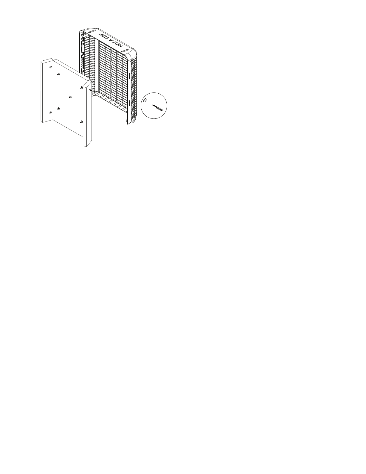
InstallationProcedures...............................................................................................................................................4
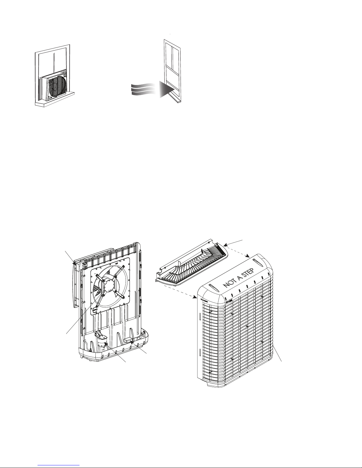
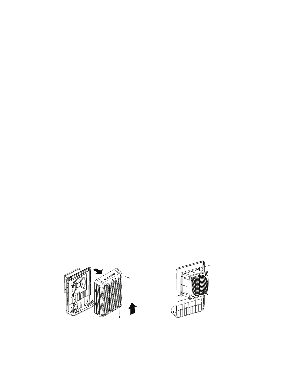
CoolerAssembly.......................................................................................................................................................4
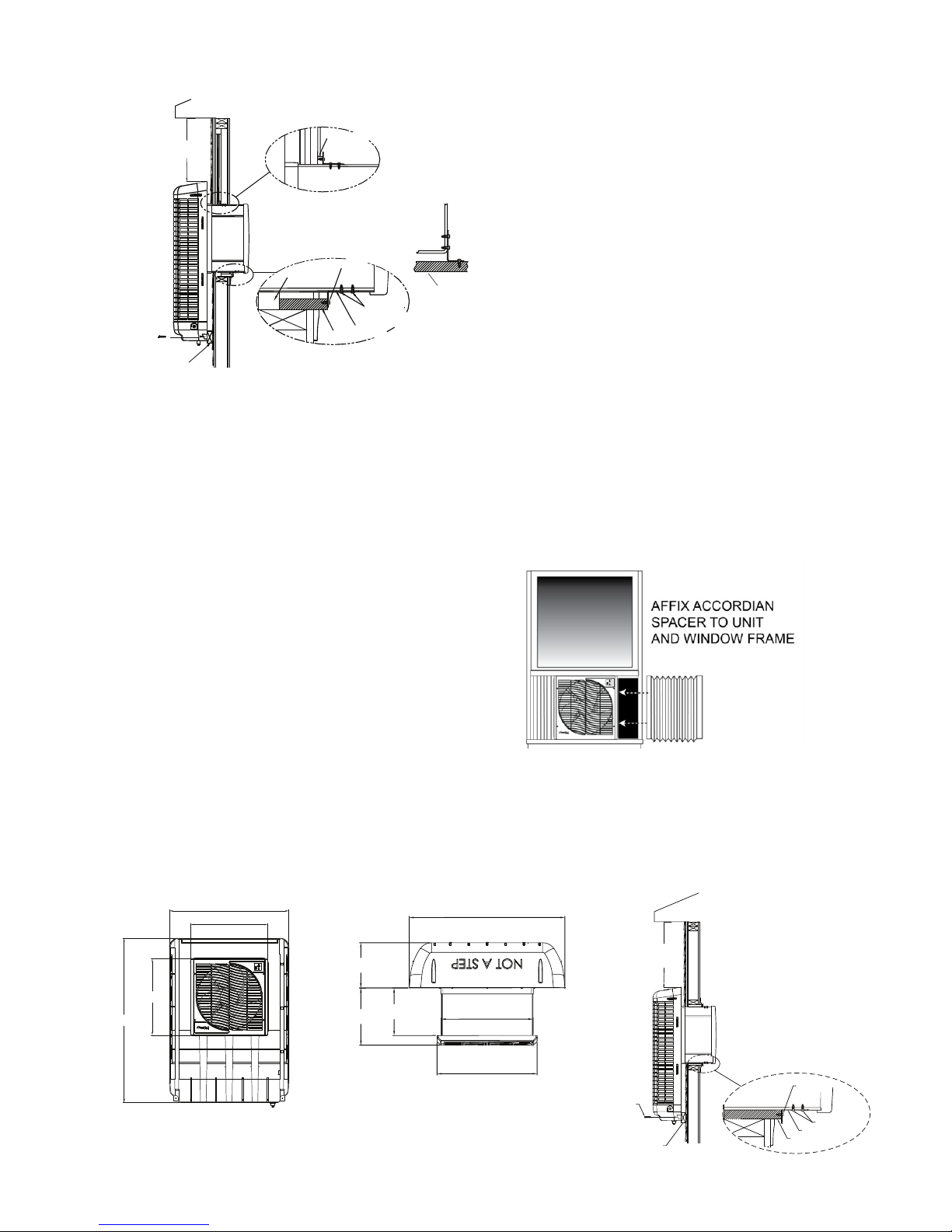
InstallationinWindow..............................................................................................................................................5
InstallationinWall....................................................................................................................................................5
WaterConnection,WaterPumpandLines,OverflowDrain,WaterLevel............................................................6
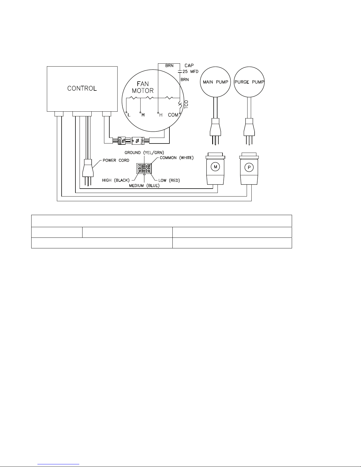
ElectricalSystem&Specifications..........................................................................................................................7
Plug‐inThermostatusage......................................................................................................................................7
OptionalPurgePump.............................................................................................................................................7
OperatingInstructions................................................................................................................................................8
UserServicingInstructions....................................................................................................................................9
AnnualMaintenance..............................................................................................................................................9
Winterization........................................................................................................................................................11
CoolerDiagramandPartsList...................................................................................................................................12
Troubleshooting...................................................................................................................................................13
Warranty..................................................................................................................................................................14
EspañolManual………………………………………………..……………………….……………………………..15
MaintenanceLog…………………………………………………………………….……..…………………………28

3
For this cooler to effectively cool
a whole house there must be open
windows or doors in each room
where cooling is desired.
NOTE: Evaporative coolers WILL NOT work in a Closed Room
EXHAUST
EXHAUST
Door or window should
be open 4 to 6 inches
NoteAboutEvaporativeCoolers:
Ventilation:
Unliketraditionalairconditioners,evaporative
coolersrequireanopenventilationsystem,not
aclosedsystem.Bothafreshairsourceandan
exhaustopeningarerequiredtoprovide
correctairflow.Typically,apartiallyopened
windowordoorineachroomwherecoolingis
desiredwillcreatecorrectairflowforoptimum
effectivenessofanevaporativecooler.
NOTE:Forbestresults,openwindows/doors
shouldnotbeonthewindwardsideonthe
house.
Waterbleedorpurge:
EvaporativeCoolersrequireacontinuoussupplyofwatertokeepthemediasaturatedformaximumcooling.
Waterpumpedintothecoolermustberemovedfromtheunittoensuremineralandbacteriabuild‐updonot
occur.Thiscanoccurwithagravity‐fedsteadybleedoffstreamoratimedpurgesystemviaapump.Apurge
pumpkit(MCP44‐PPK)isavailableatwww.championcooler.comorat800.643.8341toorder.
CAUTION:Waterexpelledfromthecoolermustberoutedawayfromanyareasthatcoulddodamageto
foundationsorothervulnerableareas.
NOTE:Drawingsinthismanualareforillustrativepurposesonlyandmayreflectslightdifferencesdepending
ondesignlevelandconfiguration.
FeaturesoftheMasterCool®MCP59WindowCooler
Thiscooler’shousingandframearemadeofheavy‐dutyUltraVioletresistantplastictoprovidealightweight,
easilyinstallablecooler.Theunitisconstructedintwobasicsectionstofacilitatequickinstallationinto
traditionalsashwindowsorsliderwindows.
Thehigh‐efficiencyrigidmediaofferssuperiorcoolingoverothertypesofevaporativecoolers.
WATER PUMP
FAN MOTOR
FLOAT
EXTERIOR PORTION
MEDIA GUARD
WATER DISTRIBUTION TRAY
FAN HOUSING
WITH REMOVABLE
FASCIA

4
NOTE:BEFOREINSTALLINGUNIT,TAKEAMOMENTTORECORDTHESERIALNUMBERANDWRITEITONTHE
MANUALCOVERINTHESPACEPROVIDED.
INSTALLATIONPROCEDURES
WARNING:Donotconnectelectricalpowertotheunituntiltheinstallationiscompleted.
TheMasterCoolMCP59coolercanbeinstalledinasash‐styleoraslider‐stylewindow.
Alternatively,thisunitisapprovedforin‐wallinstallations.
Inallinstallations,thefollowingclearancesarerequired:
Width:22”;Height:22” 4”clearanceabovetheexteriorcabinetisneededformaintenance.
NOTE:Ensurethelocationselectedforinstallingtheunitisstrongenoughtosupporttheunitandwillaccept
themountinghardware.Theoperatingweightofthecooleris93pounds.
NOTE:Aminimumoftwopeopleisrequiredforinstallation.
PartsIncluded:
CoolerUnit
Mountingbrackets(4)
Accordionspacers(2)Hardwarekit
Tools&MaterialsRequired:
Drill(powerorcordless)
Assorteddrillbits(fordrillingpilotholesformountinghardware)
AdjustableWrench
PhillipsHeadScrewdriver
Siliconeorall‐weathercaulkforsealinginfillpaneltowindowframe
Lengthof¼”copperorplastictubing
Sillcockvalve
Bubblelevel
Spacermaterial(asrequired)
CoolerAssembly
Removeunitfrombox.Verifythatallpartsareincluded.
1. Removeallpackingmaterials.
CALL1‐800‐643‐8341IFYOUFINDPARTSMISSINGORHAVEANYQUESTIONS
2. Withtheunitinanuprightposition,remove4screwsholdingthebackmediaguard,andseparatethefront
andbacksections.Pullthefanassemblyforward(about6”)untilitisfullyengagedwiththematingpart
andsecureinplaceusingthe12suppliedscrews.Verifythatassemblyissecuretopreventvibration
betweenthetwosections.
EXTEND HOUSING AND
ATTACH IT TO
COOLER BODY FRONT
WITH 12 SCREWS
1. REMOVE 4 SCREWS FROM
BACK MEDIA GUARD
2. PUSH UP ON BACK GUARD
3. PULL BACK GUARD
AWAY FROM UNIT
OPEN UNIT UP SECURE FAN HOUSING

5
InstallationinWindow
2. Closingthewindowmayhelpholdtheunitinplaceduringthefollowingsteps–Pushtheunitintothewindow
untilthebottomisflushwiththeoutsidewallorspacer(notsupplied)asshownintheillustration.
3. Makesureunitislevel.Fromtheinterior,locatethetwotracksonthebottomofthefanassembly.Drill
pilotholesasnecessaryandinstallthetwowindowsillbracketsasshowninillustration.
4. Securethetopofthefanhousingtothewindowframewithtwoadditionalbracketsandscrews.
5. Fromtheoutside,securetheunittotheexterior
wall(orspacer)withtwoscrewsatthebaseofthe
backcover(asshowninillustration.)Completethe
installationoftheexteriorportionwithtwoscrews
atthetopofthebackmediaguard.
6. Withtheunitnowinstalledinthewindow,attach
oneaccordionspacertoeachsideofthefan
assemblyusingtheadhesivebackededges.Short
screws(notincluded)canbeusedforamore
secureinstallation.(Makesurescrewsdonot
interferewithfanblade)
7. Onceaccordionspacersareinstalled,sealanygaps
aroundtheunitswithsiliconeorallweathercaulk(notsupplied).
InstallationinWall
Thiscoolerisapprovedforin‐wallinstallation.Contactalicensedcontractorforhavingthecoolerinstalledinan
outsidewall.
1.Removescreen(asneeded)andmakesure
windowisopenedtoitsmaximumheight.
Fromtheexteriorofthewindow,slidethefan
assemblysectionintothewindow.Havethe
personontheinterioradjusttheexact
placementoftheunitforaestheticsand
correctlengthsofthetwoaccordionspacers
(included).
Note:Afteridentifyingthepositionfor
installation,placeabubblelevelontopofthe
unitandmakeadjustmentstoensuretheunit
willbelevelwheninstallationiscomplete.Itis
recommendedtoverifyunitislevelatvarious
pointsduringinstallation.
"
46
1/8
21
5/8
"
21
5/8
"
33 5/8
12
3/8
"
10
5/16
"
"
9
3/4
"
33
5/8
"
19
13/16
"
21
5/8
"
FRONT VIEW TOP VIEW
SILL BRACKET
SILL PLATE
SCREW
SCREWS
SPACER TO ENSURE
FLUSH/SQUARE
INSTALLATION
SCREWS
4" MINIMUM
(NOT SUPPLIED)
SCREW
WINDOW
SCREWS
WINDOW SILL BRACKET
WINDOW SILL
WINDOW
2 PLACES -
MINIMUM 14” APART
OPTIONAL MOUNTING
WINDOW SILL
SCREW
SPACER TO ENSURE
FLUSH/SQUARE
INSTALLATION
(NOT SUPPLIED)
4” MINIMUM

6
PLASTIC OR
COPPER LINE
TO COOLER
SHUT OFF VALVE
SILLCOC
K
STD. HOSE CONNECTION
WATER LEVEL
2˝
WaterConnection
NOTE:Astandardsillcockwithwatervalveattached(locallyavailable)will
berequiredtoconnectthewatersupplytothecooler.
1.Steadywatersupplyisrequiredforoperationofthecooler.Iftakingwater
fromanexternalwaterfaucet,installasillcockandshutoffvalve.
2.Installplasticorcopperlinetosillcockandconnectittothefloatvalve.
WaterPumpandLines
Aself‐containedwaterpumpcontinuously
circulateswaterthroughthewaterdistribution
systemandoverthemedia.
Thepumpandwaterlinesareshippedunconnected.
ConnecttheWaterLines
1. Locatetheblackwaterlinesnappedintoplastic
keepersinsidetheunit.
2. Attachthebottomendofthemainwaterlineto
thepumpinlet.
3. Removethenippleinsertedintotheendofthe
overflowline.Pushoverflowhoseintooneofthe
slotsinthesidesoftheoverflowdrainfitting.
4.Reinsertthenippleintotheoverflowline.
5. Attachthetopofthehosetothewaterdistributiontray.
6. Ensuretherearenokinksinthewaterlinesafter
completion.
OverflowDrain
1. Slidetherubberwasherovertheoverflowfittingandpushthroughtheholeinthebottomofthecoolerfrom
thetopside.
2. SecurethedrainfrombeneaththepanwiththeLockNut.
Makesuretherubberwasherdoesnottwistwhiletightening,
whichcouldcauseittoleak.DONOTOVERTIGHTEN.
3. Ifleakageoccursafterreservoirisfull,retightentheoverflowfittinguntil
leakingstops.Asmallamountofsiliconecaulkmaybeusedifnecessary.
4. Attachadrainhosetothebottomofthefittingifnecessary.
WaterLevel
Twoinchesofwater
shouldbemaintained
inthebottomofthecoolertoensuresufficientwater
forcorrectoperationofthecooler.
Thefloatisfactory‐installedtomaintaina2inch
levelofwater,butmayrequireadjustmentifshipping
orinstallationhascausedthesettingtoshift.
FLOAT VALVE
WATER LINE
ATTACH POIN
T
MAIN
WATER
LINE
JUNCTION
REINSTALL NIPPLE INTO
OVERFLOW LINE
(AFTER
INSERTING
LINE THROUGH
OVERFLOW
FITTING)
PUMP
(STRAINER NETTING
NOT SHOWN
FOR CLARITY)
PUMP
INLET
OVERFLOW
DRAIN
FITTING
NIPPLE
REMOVE NIPPLE FROM
TUBE BEFORE FEEDING
IT INTO DRAIN OVERFLOW.

7
ElectricalSystem
Theelectricalsystemdoesnotrequiregeneralmaintenance.Thefollowingwiringdiagramissuppliedfor
referenceonly.
ELECTRICALSPECIFICATIONSOFMCP59COOLERS
MCP59FanMotor:120V;3.34AmpsMainPump:120V;0.9Amps
IfOptionalPURGEPUMPisinstalledAdditional0.9Amps
Plug‐InThermostatUsage
TheMCP59canbecontrolledbyaplug‐inprogrammablethermostat.Thesethermostatsarelocallyavailable,
andenableprecisetimingandtemperaturecontrolviaanelectronicthermostatthatplugsintoa110voltoutlet.
TousesuchadevicewiththeMCP59,followtheinstructionsforthespecificthermostatandplugthecoolerinto
theoutletonthethermostat.
OptionalPurgePump
Inadditiontothestandardwaterpumptorecirculatewaterfromthereservoir,apurgepumpcanbeinstalledto
evacuatethecontentsofthereservoirevery6hours.Thishelpsretardbacterialgrowthandmineralbuildupon
themedia,extendingitslife.Italsomaintainsfresherairinthehome.Theuseofthepurgepumpisactually
moreeconomicaltousethanacontinualbleedline.Thepurgepumpkit(P/NMCP44‐PPK)forthisunitmaybe
purchasedonlineatwww.championcooler.comorbyphoneat1.800.643.8341.
PurgePumpDischarge
NOTE:Thewaterejectedatthetimeofpurgingwillbeexpelledatahighrateofspeed,andmustberouted
awayfromthefoundationofthehomeorotherareaswhererushingwatercoulddodamage.
1. Attachastandardwaterhosetotheoverflowdraintodirectthewaterawayfromthehouse.
NOTE:Thiswaterisnotpotable,butcanbeusedforwateringvegetableorflowergardens.
(OPTIONAL
OWNER-INSTALLED
PURGE PUMP)

8
FAN
HI MED LO
on
off
PUMP
Power
Fan Speeds:
Water Pump
On/Off
Indicator
Lights
OPERATINGINSTRUCTIONS
TheMCP59hasanelectronictouchcontrol
panelintheupperrighthandcorner.
Beforeturninguniton,ensureunitisplugged
in,watersupplytopumpison,andthereis
correctventilation,asshownonpage3ofthis
manual.
Note:Theseunitsmaybecontrolledusingthe
3buttonsonthefrontpanelofthecooleror
withtheremotecontrol.
On/Off
Thisbuttoninitiatespowertotheunit.When
firstplugged,pressingON/OFFwillstartthe
unitinthedefaultsetting(pumpONandFan
onHIGH).Afteritsinitialuse,thelast
operatingsettings(forfanandpump)willbe
reinstatedwhentheunitisturnedonagain.
Pressingthisbuttonwhentheunitisalreadyrunningwillturnbothfanandpumpoff.
AfterAPowerFailure:Oncepowerisrestored,theunitwillrestartinthesamesettingsasbeforepowerwas
lost.
Pump
Thisbuttontogglesthepumponandoff.WhentheLEDislit,thepumpisrunning.
Thepumpmustbeonwhileoperatingthefanfortheunittooperateasanevaporativecooler,thoughtheunit
canbeusedinfanmodewithoutthepump,ifdesired.
Note:Forbestresultsturnonthepumpforafewminutestowetthepadsbeforeoperatingthefan.
Fan
PressingthefanbuttoncyclestheunitfromHIGH,toMEDIUMtoLOWspeedsandthenOFF.
PleaseNote:Thereisatwoseconddelayfromthepressingofthebuttonforthefantoengageorchange
speeds.Thisappliestothefrontcontrolpanelandtheremotecontrol.
RemoteControl
Theremotecontrolsuppliedwiththiscoolerallowsyoutoturntheuniton
oroff,controlfanspeedandinitiatethepump.Thebuttonsoperateinthe
samemannerasthoseonthefrontcontrolpanel.
Theremotecontrol’srangeisapproximately20feetwithinsightofthe
cooler.ItusestwoAAalkalinebatteries(included).Awallmountable
holderisalsosuppliedwiththecooler.
ON
PUMP
CHAMPION / ESSICK AIR
FAN
UNIT POWER ON/OFF
PUMP ON/OFF
FAN SPEED (1-3)

9
USERSERVICINGINSTRUCTIONS
Maintenanceonevaporativecoolersisminimal,butveryimportanttotheproperoperationandeffectiveness
ofyourcooler.Periodicinspectionofthecooler’sinteriorwillreducethepotentialforsubstandardcoolingdue
toinsufficientorunevenwaterdistribution.
NOTE:Forgeneralmaintenancepurposes,theunitmayberapidlydrainedofwaterbyremovingtheoverflow
fittingfromthebottomoftheunit.Thisisnotadequatedrainingforwinterization(seeproceduresunder
Winterizationsection.)
AnnualMaintenance(MaybeNeededMoreOfteninAreaswithHardWater)
Cleaning
WARNING:Disconnectfromelectricalpowerandturnunitoffduringallmaintenance.Turnwatersupplyoff
beforeremovingbackforcleaningormaintenance.
1. Removethebackmediaguard(asshownbelow).
2. Inspectpadsinplace.Removemediapadsfromback
guardbyunscrewingthemediapegclips.
Becarefulnottochipordamagethemediawhile
removing.Visuallyinspectbothsidesofmediapads.
Lookforblockage,mineralbuild‐upormildewgrowth,
breakageorotheranomalies.
NOTE:
Whenever removing
the back from the
cooler, always verify
the water supply
tube is reconnected
to the water
distribution tray
before operating the
cooler.
LOCATE MEDIA PEGS AND REMOVE.
OR PULL CLIPS
OFF PEGS FROM
THE INTERIOR.
USING PLIERS,
PULL PLUGS
OUT FROM THE
EXTERIOR.

10
3. Washpadswithagardenhose.Donot
useapressurewasher.
4. Checkwaterdistributorforblockage
orexcessivebuildupofdust.
5. Setmediainasafeplaceuntilall
maintenanceiscomplete.
6. Washoutreservoirthoroughlyusinga
softbristlebrush.Useplentyofwater
toremovealgaegrowth.
Cleanareasaroundpump,strainer
andfloattoensurenoalgae
growthremains.
CAUTION:Donotuseharshchemicals(likechlorinebleach)tocleantheinteriorportionsofthecooler.Donot
useabrasivecleanersontheexteriorofthecoolerbodytomaintainitsUVresistance.
7. Rinsethoroughlyafterusinganycleaningsolutionsontheinteriororexterioroftheunit.
WaterSystemPump:
1. Thewaterpumpisaself‐containedunitthatshouldrequirenomaintenanceotherthanensuringthatno
debrisorcorrosioninterfereswithfreemovementoftheparts.
2. Ensurehoseconnectiontopumpisingoodcondition.
WaterFloat:
1. Thefloatlevelisfactorysetforoptimumperformance,howevermoderateadjustmentscanbemadeby
bendingthefloatarmforadifferentwaterlevel.
2. Themaximumrecommendedwaterlevelisapproximatelytwoinches(theheightoftheoverfloworifice.)
WaterDistributor
1. Inspectthewaterdistributionsectiontoensureallorificesareclear.
2. Verifythehoseconnectionsareingoodorderandnokinksortearsarepresent.
WaterDrainOverflow
1. Unscrewthedrainoverflowpipeandchecktheconditionofthegasketatthebottomofthefixture.When
reinstalling,ensurethestandpipefixtureissecureandthereisnoleakageafterthereservoirisfilled.
NOTE:Ifduringusageofthecooleryoustartnoticinglowsaturationofpadsandinsufficientcooling,or
leakagefromthecooler,checktheO‐ringatthebaseofthestandpipe.Thisisthemostlikelycauseofleakage
onthisunit.
OptionalWaterPurgePump(ifinstalled)
1. Ifapurgepump(MCP44‐PPK)hasbeeninstalledontheMCP59,checkthatthepurgepumpandstrainer
arecorrosion‐freewithfreelymovingparts.
MediaPadReplacement
1. Whenthemediapadshavebecomeencasedwithmineralbuildup,brokenordamaged,replacethemwith
GenuineMunter’sreplacementpads,modelMCP44‐PAD.Youmaypurchasethemonlineat
www.championcooler.comorbycalling1.800.643.8341.

11
Winterization
TheMCP59coolerisdurableenoughtobeleftinstalledduringthewinter,thoughafewprecautionsmustbe
takentoensurenowaterfreezesintheunitorlines.
Ifthetemperaturesinyourareadropwellbelowfreezingitmaybewisetoremovethewatersupplylinefrom
theoutsidefaucet.
Draining
MCP59:
1. Turnthewatersupplytothecooleroff.
2. Turnoffandunplugcooler.Remove4screwssecuringthebackmediaguardandaccessinteriorofunit.
3. Soakupanyremainingwaterandensureallwaterisdrainedfromboththewaterpumpandthepurge
pump.
4. Disconnectanddrainthewaterhosesandwaterdistributor.
MCP59(withoptionalowner‐installedpurgepump,modelMCP44‐PPK):
1. Turnoffthewatersupplytothecooler.
2. Turnoffandunplugcooler.
3. Removefourscrewssecuringthebackmediaguardandaccesstheinterioroftheunit.
4. Soakupanyremainingwaterandensureallwaterisdrainedfromboththewaterpumpandthepurge
pump.
5. Disconnectanddrainthewaterhosesandwaterdistributor.
6. Replacethemediaguard.
Covering
1. Anoptionalexteriorfittedcover,modelMCP44‐ECisavailableforpurchaseonlineat
www.championcooler.com,atretailoutletsorbycalling1.800.643.8341.
2. Anoptionalinteriorgrillecover,modelMCP44‐ICtokeepairfromenteringthehomethroughthewindow
isavailableatwww.championcooler.com,aretailoutletor1.800.643.8341.
a. Usethesnaponclipsmoldedintothecovertosecurethecovertothegrille.

12
4
3
8
7
9
12
(2 ea.)
19
(4 ea.)
1
5
21
13
11
17
15
16
20
6
18
ON
PUMP
CHAMPION / ESSICK AIR
FAN
22
MCP44 (1 pump)
14
Optional Accessories
24
23
Interior Cover Exterior Cover
OPTIONAL
OWNER INSTALLED
PURGE PUMP
2
OPTIONAL
PURGE PUMP KIT
10
CoolerDiagramandPartsList
ItemDescriptionPartNumber
1CoolerBack/MediaGuard72243
2Setof4screwsforattachingbackguard72303
3BackMediaPad;2"X24"X35.5"CelDek72244
4SideMediaPad;2"X5.88"X35.5"CelDek(2ea.)72245
5Waterdistributortray72249
6Traycap72250
7MediaPegClip;windowcooler;PP(9ea.)72246
8MediaPeg;windowcooler;PP(9ea.)72247
9Pumpassy.–Mainwatersystem 72402
10Purgepumpkit.(OptionalAccessory)MCP44‐PPK
11WaterDistributionHoseassy.72256
12Floatvalve72290
13Coolerbodyfront72242
14Receptaclecover72407
15Fanmotor72842
16Fanblade72253
17Fanhousing72251
18Grille 72257
19Grillescrewcaps72260
20Controlmodule72258
21Vinylaccordionwindowpanel(2ea.)72284
22Remotecontrol72302
23InteriorGrilleCover–availableforpurchaseMCP44‐IC
24ExteriorCoolerCover–availableforpurchaseMCP44‐EC
‐‐ MediaPadReplacementSet(notillustrated)MCP44‐PAD

13
TroubleShootingChart
PROBLEMPROBABLECAUSESOLUTION
Unitwillnotstarta.NoPower
b.TrippedCircuitBreaker
c.Blownhomefuse
d.Electricalfault
a.Verifyunitpluggedin;
andoutletisfunctional
b.ResetCircuitBreaker
c.Replacehomefuse
d.CallChampionHelpline
InsufficientCoolinga.Inadequatewaterdistribution
(padsnotsaturated)
b.Padsdirtyorcoveredwith
mineraldeposits
a.Checkwaterdistributiontrayand
hoseforblockages.
‐Verifypumpoperatingcorrectly
‐Checkwatersupplyforcorrectflow
b.Washdirt&depositsoffpads
orreplacepads
Waterinairstreama.Watersystemhasleaksor
looseconnections
b.Waterisnotbeingabsorbed
bymediapads,andentering
straightintoairflow
a.Checkallwaterconnections,tubing,
distributiontrayforloosefittings,
leakageortears.
b.Checkconditionofpads.Cleanor
replaceasnecessary.
Highindoorhumidity a.Insufficientairflow
b.Unsatisfactoryexhaust
a.Increasefanspeed
b.Opendoorsorwindowsmore
Odorinhomea.Occursinitiallywhenpadsare
firstsaturated.
b.Bacterialgrowthinreservoir
c.Airintakeispickingup
ambientodorfrom
surroundings
a.Normal.Willdissipateshortly.
b.Cleanunitregularlywithdisinfectant
oraddaliquidbacteriostatintothe
watertank
c.Removesourceofodorormove
coolertoanotherwindow
Rapidmineralbuildup
onmediapads
a.Hardwater a.Increasemaintenancecycleand
washoffscalemoreoften.Check
orificesareclearofmineralbuildup.

14
MASTERCOOL MCP WINDOW COOLER
ONE YEAR LIMITED WARRANTY
SALES RECEIPT REQUIRED AS PROOF OF PURCHASE FOR ALL WARRANTY CLAIMS.
This warranty is extended only to the original purchaser of this evaporative cooler when the unit
is installed and used under normal conditions against defects in workmanship and materials as
follows:
One (1) year from date of sale on the unit, and
Five (5) years on the evaporative media, which is considered a disposable component
and should be replaced periodically, and
Two (2) years on motor.
The manufacturer will replace the defective part/product, at its discretion, with return freight paid
by the manufacturer. It is agreed that such replacement is the exclusive remedy available from
the manufacturer and that TO THE MAXIMUM EXTENT PERMITTED BY LAW, THE
MANUFACTURER IS NOT RESPONSIBLE FOR DAMAGES OF ANY KIND, INCLUDING
INCIDENTAL AND CONSEQUENTIAL DAMAGE OR LOSS OF PROFITS OR REVENUES.
Some states do not allow limitations on how long an implied warranty lasts, so the above
limitations may not apply to you.
Exclusions from this warranty
We are not responsible for any incidental or consequential damage from any malfunction,
accident, misuse, alterations, unauthorized repairs, abuse, including failure to perform
reasonable maintenance, normal wear and tear, nor where the connected voltage is more than
5% above the nameplate voltage.
Alterations include the substitution of name brand components including, but not limited to
media pads.
We are not responsible for any damage from the use of water softeners or treatments,
chemicals or descaling materials.
We are not responsible for the cost of service calls to diagnose the cause of trouble, or labor
charge to repair and/or replace parts.
No employee, agent, dealer or other person is authorized to give any warranties or conditions
on behalf of the manufacturer. The customer shall be responsible for all labor costs incurred.
Some states do not allow the exclusion or limitation of incidental or consequential damages, so
the above limitations or exclusions may not apply to you.
How to obtain service under this warranty
Within the limitations of this warranty, purchaser with inoperative units should contact the dealer
where you purchased the cooler. If for any reason you are not satisfied with the response
from the dealer, contact Customer Service at 800-643-8341 for instructions on how to obtain
service within warranty as listed above.
This warranty gives the customer specific legal rights, and you may also have other rights which
vary from province to province, or state to state.
Register your product at www.championcooler.com.
MasterCoolbyChampionCooler
5800MurraySt.
LittleRock,AR72209
800.643.8341
www.championcooler.com

15
FelicitacionesporhabercompradoelenfriadorevaporativoplásticoMasterCool®MCP59.
Estaunidadsefabricóconelpropósitodebrindarleunenfriamientoconfiableyeficienteduranteaños.
NOTA:LEAESTASINSTRUCCIONESANTESDEINSTALARELENFRIADOR.Sigaatentamentelasinstruccionesde
instalacióndeestemanual.Encasocontrario,podríanocasionarseproblemasrelacionadosconlaseguridady
invalidarlagarantía.
Instruccionesdeseguridad
1. Uselaunidadúnicamenteconuntomacorrientemonofásicoconconexiónatierrade110Vy60Hz.
2. AsegúresedequeelenfriadorestéAPAGADOyDESENCHUFADOantesderealizarlainstalación,el
mantenimientoolalimpiezadelaunidad.
3. Nooperelaunidadconuncableoenchufedañadoniconotraspiezasdañadasofaltantes.
4. No haga funcionar el cable debajo de la alfombra. No cubra el cable con alfombras, alfombrillas o
revestimientos similares. No cable de ruta debajo de los muebles o electrodomésticos. Coloque el
cable lejos del área de tráfico y donde no se pueda tropezar.
5. Noopereelenfriadorconlaprotecciónposteriordelmedioextraída.
6. Noutiliceuncableprolongadorparaoperarelenfriador.
7. Nouseunadaptadorparaconvertirelconectordetresclavijasparautilizarenuntomacorrientesin
conexiónatierrade2espigas.
8. NOlouseconundispositivodecontroldevelocidaddeestadosólido.Silohace,podríaocasionarun
incendioodescargaeléctrica.
9. Noalterenimodifiqueesteenfriador.
10. Loscomponenteseléctricosdebenserreparadosoreemplazadosúnicamenteporelectricistas
calificados.
Nopermitaqueniñosoperenorealicenlainstalaciónoelmantenimientodelenfriador.11.
Esteventiladornosepuedeutilizarcomounextractordeaireenlacocina,ydebetenerunmínimode12.
3piesdelallamaabierta.
Índice
Instruccionesdeseguridad..........................................................................................................................................15
FuncionesdelenfriadordeventanaMasterCool®MCP59..........................................................................................16
PROCEDIMIENTOSDEINSTALACIÓN............................................................................................................................17
Montajedelenfriador.............................................................................................................................................17
InstalaciónEmpotrada............................................................................................................................................18
Conexióndeagua....................................................................................................................................................19
Bombadeaguaytuberías.......................................................................................................................................19
Conectelastuberíasdeagua..................................................................................................................................19
DesbordedeDrenajedeagua.................................................................................................................................19
Niveldeagua...........................................................................................................................................................19
Usodeltermostatocomplementario......................................................................................................................20
OpcionalBombadepurga.......................................................................................................................................20
INSTRUCCIONESDEUSO..............................................................................................................................................21
ServicioUsuarioInstrucciones................................................................................................................................22
Mantenimientoanual(puedesernecesariaunamayorfrecuenciaenáreasconaguasduras)............................22
Acondicionamientoparaelinvierno............................................................................................................................24
Diagramadelenfriadorylistadepiezas.................................................................................................................25
Garantia....................................................................................................................................................................27
MentenimientodelosRegistros................................................................................................................................28
En
f
r
i
a
d
orEvaporat
i
vo
d
eVentana
d
e
l
MasterCoo
l®
MCP59
Instruccionesdeusoeinstalación

16
Notaacercadelosenfriadoresevaporativo:
Ventilación:
Adiferenciadelosacondicionadoresdeaire,
losenfriadoresevaporativonecesitanunsistemade
ventilaciónabiertoynocerrado.
Serequierentantounafuentedeairefrescocomouna
aperturadeescapeparagenerarunacorrectacirculación
deaire.Típicamente,unaventanaparcialmenteabiertao
lapuertaencadacuarto(espacio)dondedeenfriamiento
esdeseadacrearánlacorrientedeairecorrectoparala
eficaciaóptimadeunenfriadorevaporativo.
NOTA:Paramejoresresultados,lasventanas/puertas
abiertasNODEBENestarenlapartedelacasa
enfrentadaalviento.
Purgadeagua:
Losenfriadoresevaporativorequierenunsuministrodeaguacontinuoparamantenersaturadoelmedioylograrun
máximoenfriamiento.Deberetirarsedelaunidadelaguabombeadadentrodelenfriadorparaevitarlaacumulación
demineralesybacterias.Estopuedesucederporaccióngravitatoriadeunflujodedescargaconstanteoporun
sistemadepurgaprogramadoatravésdeunabomba.Labombadepurga(MCP44‐PPK)estádisponibleen
www.championcooler.comollamandoal1.800.643.8341.
ADVERTENCIA:Elaguaexpulsadadelenfriadordebedirigirselejosdecualquieráreaquepudieraafectarlos
cimientosuotraszonasvulnerables.
NOTA:Losdibujosdeestemanualsonparafinesilustrativosypuedenreflejarpequeñasdiferenciasenfuncióndelas
diferenciasdediseñoyconfiguración.
FuncionesdelenfriadordeventanaMasterCool®MCP59
Lacarcasaylaestructuradeesteenfriadorestánrealizadosenunplásticoreforzadoyresistentealosrayos
ultravioleta,loquedacomoresultadounenfriadorlivianoydefácilinstalación.Launidadestáconstruidaendos
seccionesbásicasparaposibilitarunarápidainstalacióndentrodeventanasaguillotinaocorredizas.
Elmediorígidodealtísimaeficienciabrindaunenfriamientosuperior,comparadoconotrosenfriadores
aevaporación.
BOMBA DE AGUA
CARCASA DEL VENTILADOR
C/ FRENTE DESMONTABLE
MOTOR DEL
VENTILADOR
FLOTADOR
SECCIÓN EXTERIOR/
PROTECCIÓN DEL MEDIO
BANDEJA DE DISTRIBUCI
Ó
N
DE AGUA
Para enfridaor trabajar mejor, tiene que
haber una vnetana o puerta abierta
en cada habitacion donde
el enfriamiento
es deseado.
NOTA: Elos enfriadores evaporativo NO funcionan
en habiaciones cerradas
ESCAPE
ESCAPE
Ventana o puerta
abierta 4-6 pulgades

17
NOTA:ANTESDEINSTALARLAUNIDAD,TÓMESEUNMOMENTOPARAANOTARELNÚMERODESERIEY
ESCRIBIRLOENLACUBIERTADELMANUALENELESPACIOPROVISTO.
PROCEDIMIENTOSDEINSTALACIÓN
ADVERTENCIA:Noconectelaunidadhastahabercompletadolainstalación.
ElenfriadordeventanaMasterCoolMCP59sepuedeinstalarenunaventanaaguillotinaocorrediza.
Comoalternativa,estaunidadseaprobóparainstalacionesempotradas.Todaslasinstalacionesrequierenel
siguienteespaciolibre:
Ancho:22";Altura:22";Esnecesariounespaciolibrede4"porencimadelacajaexteriorparamantenimiento.
NOTA:Asegúresedequelaubicaciónelegidaparalainstalaciónsealosuficientementeresistentecomopara
soportarelpesodelaunidadylaspiezasdemontaje.Elpesooperativodelenfriadoresde93libras.
NOTA:Serequierenalmenosdospersonasparainstalaresteenfriadordeventana.
Piezasincluidas:
Unidaddeenfriamiento
Soportesdemontajedeantepechodeventana(4)
Juegodepiezasdeseparadoresdeacordeón(2)
Herramientasymaterialesrequeridos:
Taladro(concableoinalámbrico)
Brocassurtidas(pararealizaragujerosguíaparalaspiezasdemontaje)
Llaveajustable
DestornilladorPhillips
Siliconaomasillaparatodotipodeclimaparasellarelpanelderellenoalaestructuradelaventana
Tuberíadecobreoplásticode¼"delongitud
Válvuladegrifodemanguera
Niveldeburbuja
Montajedelenfriador
Retirelaunidaddelacaja.Verifiquequeincluyatodaslaspiezas.
1. Retiretodoelmaterialdeembalaje.
ENCASODEPREGUNTASOSIENCUENTRAQUEHAYPARTESFALTANTES,
LLAMEAL1‐800‐643‐8341
2. Conlaunidadenposiciónvertical,retirelos4tornillosdelaseccióndeespalda.Retireelmódulodel
ventiladorhaciaadelante(aproximadamente6")hastaqueestétotalmenteencajadoenlacontrapiezay
asegúreloensuposiciónutilizandolos12tornillosincluidos.Compruebequeelmóduloestéfijoparaevitar
vibracionesentrelasdossecciones.
EXTIENDA LA CARCASA Y
SUJÉTELA AL FRENTE DEL
CUERPO DEL ENFRIADOR
CON 12 TORNILLOS.
1.
RETIRE LOS 4 TORNILLOS
DE LA SECCIÓN DE ESPALDA
2. EMPUJAR HACIA ARRIBA EN
LA SECCIÓN DE ESPALDA
3. SEPARE LA SECCIÓN DE LA UNIDAD
ABRA LA UNIDAD SUJETE LA CARCASA DEL VENTILADOR

18
InstalaciónenVentana
2. Cierrelaventanaparaayudarasostenerlaunidadenposicióndurantelossiguientespasos:Empujelaunidaddentrodela
ventanahastaqueelfondoquedealrasdelaparedexterioroelseparador(noincluido),talcomoseilustra.
3. Asegúresedequelaunidadesténivelada.Desdeelinterior,ubiquelosdosrielesenelfondodelmódulodel
ventilador.Realicedosagujerosguíasegúnseanecesarioeinstalelosdossoportesdelantepechodela
ventana,talcomoseindicaenlailustración.
4. Asegurelapartesuperiordelacarcasadelventiladoralaestructuradela
ventanacondossoportesytornillosadicionales.
5. Desdeafuera,asegurelaunidadalaparedexterior(oseparador)
condostornillosenlabasedelatapaposterior(comoindicala
ilustración).Completelainstalacióndelaparteexteriorcondos
tornillosenlapartesuperiordelaprotecciónposteriordelmedio.
6. Unavezinstaladalaunidadalaventana,acopleunseparadorde
acordeónacadaladodelmódulodelventiladorconlosbordesde
fondoadhesivo.Puedenutilizarsetornilloscortos(noincluido)
paraobtenerunainstalaciónmássegura.(Cercióresedequelos
tornillosnointerfieranconlasaspasdelventilador).
7. Unavezinstaladoslosseparadoresdeacordeón,sellecualquierhuecoquehayaquedadoalrededordela
unidadconsiliconaomasilla(noincluido)paratodotipodeclima.
InstalaciónEmpotrada
Esteenfriadorseaprobóparainstalacionesempotradas.Póngaseencontactoconuncontratistaautorizadopara
queinstaleelenfriadorenunaparedexterna.
VENTANA
TORNILLO
ANTEPECHO
DE VENTANA
ALFÉIZAR DE LA VENTANA
DE MONTAJE OPCIONAL
TORNILLOS
SEPARADOR
SEPARADOR
PARA GARANTIZAR
PARA GARANTIZAR
ENRASADO / INSTALACION
A ESCUADRA
A ESCUADRA
2 LUGARES MÍNIMO
14' APARTE
SOPORTE DE MONTAJE DE
ANTEPECHO DE VENTANA
TORNILLOS
4”
MINIMUM
1. Extraigalapantalla(siesnecesario) yasegúrese
dequelaventanaestéabiertaentodasualtura.
Desdeelexteriordelaventana,deslicelaparte
delmódulodelventiladorenlaventana.
Asegúresedequelapersonaqueestéenel
interiorajustelacolocaciónexactadelaunidad
paramantenerelaspectoylaslongitudes
correctasdelosdosseparadoresdeacordeón
(incluidos).
Nota:Despuésdeidentificarlaposicióndela
instalación,coloqueunniveldeburbujaenla
partesuperiordelaunidadyrealicelosajustes
necesariosparaasegurarsedequelaunidadesté
niveladacuandosehayacompletadola
instalación.Serecomiendaverificarquelaunidad
esténiveladaendistintospuntosdurantela
instalación.
"
46
1/8
21
5/8
"
21
5/8
"
33
5/8
12
3/8
"
10
5/16
"
"
9
3/4
"
33
5/8
"
19
13/16
"
21
5/8
"
VISTA FRONTAL VISTA SUPERIOR
TORNILLO
ANTEPECHO
SEPARADOR
SEPARADOR
PARA GARANTIZAR
PARA GARANTIZAR
ENRASADO / INSTALACION
A ESCUADRA (NO INCLUIDO)
SOPORTE DE MONTAJE
DE ANTEPECHO
TORNILLOS
TORNILLOS
4" MINIMUM

19
NIVEL DE AGUA
2˝
UNIÓN
BOMBA
(NO SE MUESTRA LA
MALLA DEL FILTRO
PARA MAYOR
CLARIDAD)
TOMA DE
ENTRADA
DE LA
BOMBA
TUBERÍA DE
AGUA PRINCIPAL
CONEXIÓN DE
DRENAJE DE
DESBORDE
BOQUILLA
VUELVA A INSTALAR LA
BOQUILLA EN LA TUBERÍA
DE DESBORDE
(DESPUÉS DE
INSTALAR LA
TUBERÍA A
TRAVÉS DE LA
GRIFERÍA DE
REBOSE)
CONTRATUERCA
TUBO DE
REBOSAMIENTO
EMPAQUETADURA
DE GOMA
FONDO
DEL TANQUE
Conexióndeagua
NOTA:Senecesitaráungrifodemangueraestándarconválvula
deaguaacoplada(disponibleanivellocal)paraconectarel
suministrodeaguaalenfriador.
1. Serequiereunsuministrodeaguaconstanteparael
funcionamientodelenfriador.Siseobtieneaguadeungrifo
externo,instaleungrifodemanguerayunaválvuladecierre.
2. Instaleunatuberíaplásticaodecobrehastaelgrifode
manguerayconéctelaalaválvuladeflotador.
Bombadeaguaytuberías
Unabombaindependientehacecircularelagua
deformacontinuaatravésdelsistemadedistribución
deaguaydelmedio.Labombaylastuberíasde
aguaseenvíansinconectar.
Conectelastuberíasdeagua
1.Ubiquelatuberíadeaguanegrainsertadaenlos
sujetadoresdeplásticodentrodelaunidad.
2.Conecteelextremoinferiordelatuberíadeaguaprincipal
enlatomadeentradadelabomba.
3.Retirelaboquillainsertadaenelextremodelatuberíade
desborde.Insertelamangueradedesbordeenunadelas
ranurasenelinteriordelaconexióndedrenajededesborde.
4.Vuelvaainsertarlaboquillaenlatuberíadedesborde.
5.Conectelapartesuperiordelamangueraalabandejade
distribucióndeagua.
6. Asegúresedequenohayaplieguesenlastuberíasdeagua
unavezterminadalainstalación.
DesbordedeDrenajedeagua
1. Deslicelaarandeladegomasobredesbordamientodedrenajeyempujea
travésdelorificiodesdelapartesuperiordelenfriador,hacialaparteinferior.
2. Asegureeldesbordamientodedrenajepordebajodelabandejaconla
contratuerca.Asegurequelaarandelanosetuerzamientrasselaestá
apretando,puesestopuedecausarfiltración.NOLAAPRIETEDEMASIADO.
3. Siocurreunafiltracióndespuésdellenareltanque,vuelvaaapretarel
tuboderebosamientohastadetenerlafiltración.Puedeusarseuna
pequeñacantidaddecalafateconsiliconadesernecesario.
4. Conectedrenarmanguerahastaelfondodelmontajecomosea
necesario.
Niveldeagua
Debenmantenersedospulgadasdeaguaenelfondodel
enfriadorparagarantizarelaguasuficienteparauncorrecto
funcionamientodelenfriador.
Elflotadorvieneinstaladodefábricacomoparamantener2"
deniveldeagua,peropuederequerirunajustesieltransporte
olainstalacióncausaronalgúncambioenlaconfiguración.
PLASTIC OR
COPPER LINE
TO COOLER
SHUT OFF VALVE
SILL COCK
STD. HOSE CONNECTION
VÁLVULA DE APAGADO
TUBERÍA AL
ENFRIADOR DE
PLÁSTICO O COBRE
GRIFO DE
MANGUERA
CONEXIÓN DE MANGUERA
ESTÁNDAR
PUNTO DE
CONEXIÓN
DE LA TUBERÍA
DE AGUA DE LA
VÁLVULA DE
FLOTADOR).

20
Sistemaeléctrico
Elsistemaeléctriconorequieremantenimientogeneral.Elsiguientediagramadecableadoessóloamodo
dereferencia.
ESPECIFICACIONESELÉCTRICASDELOSENFRIADORESMCP59
MCP59Motordeventilador:120V;3.34AmperiosLabombaprincipal:120V;0.9Amperios
Silabombadepurge(opcional)seinstalaAdicional0.9Amperios
Usodeltermostatocomplementario
ElMCP59puedecontrolarsemedianteuntermostatoprogramablecomplementario.Estostermostatospueden
adquirirseanivellocalypermitenuncontrolprecisodeltiempoylatemperaturaatravésdeuntermostato
electrónicoqueseconectaauntomacorrientede110V.ParautilizardichodispositivoconelMCP59,sigalas
instruccionesparaesetermostatoenparticularyconecteelenfriadoraltomacorrienteeneltermostato.
OpcionalBombadepurga
Ademásdelabombadeaguaestándarpararecircularelaguadesdeeldepósito,unabombadepurgasepueden
instalarparaevacuarelcontenidodeldepósitocada6horas.Estoayudaaretardarelcrecimientobacterianoyla
acumulaciónmineralenelmedioyasíprolongarsuvidaútil.Tambiénconservaelairemásfrescodentrodel
hogar.Enrealidad,elusodeunabombadepurgaresultamáseconómicoqueunatuberíadepurgacontinua.Elkit
debombadepurga(n.ºdepieza:MCP44‐PPK)paraestaunidadpuedeadquirirseenlíneaen
www.championcooler.comollamandoal1.800.643.8341.
Descargadelabombadepurga
NOTA:Elaguaarrojadaenelmomentodelapurgasaldráexpulsadaagranvelocidadyseladebealejardelos
cimientosdelacasauotrasáreasdondepudieraocasionardaños.
1. Anexeunamangueradeaguaestándaraldrenajededesbordeparadirigirelaguaafueradelacasa.
NOTA:Estaaguanoespotableperopuedeutilizarsepararegarhuertosojardines.
(WPL44 ONLY, OR
OWNER-INSTALLED)
(OPCIONAL, PROPIETARIO
INSTALADA)
CONTROL MOTOR DEL
VENTILADOR
MAR CAP
COM
TCO
TIERRA (AMA/VER)
CABLE DE
A
LIMENTACIÓN
ALTA (NEGRO)
MEDIA (AZUL)
BAJA (ROJO)
COMÚN (BLANCO)
BOMBA
PRINCIPAL
BOMBA DE
PURG
A
MAR
Table of contents
Languages:
Other Master cool Air Conditioner manuals

Master cool
Master cool WisperCool P400 User manual

Master cool
Master cool 69360-YF User manual

Master cool
Master cool MCP44(C) User manual

Master cool
Master cool WisperCool MMB8 User manual

Master cool
Master cool CM120A User manual

Master cool
Master cool MMBT12 User manual

Master cool
Master cool MCP44 User manual

Master cool
Master cool MMB10 User manual
Popular Air Conditioner manuals by other brands

Technibel
Technibel MCAV77C5VAB Technical data & service manual

Daikin
Daikin VRV III REMQ8P8Y1B installation manual

MrCool
MrCool Signature Series Owners & installation manual

ALPATEC
ALPATEC AC 12 FIT user manual

Fujitsu
Fujitsu AGYG09LVCB Service manual

Convair
Convair ClimateMaster CM12RW instruction manual