10
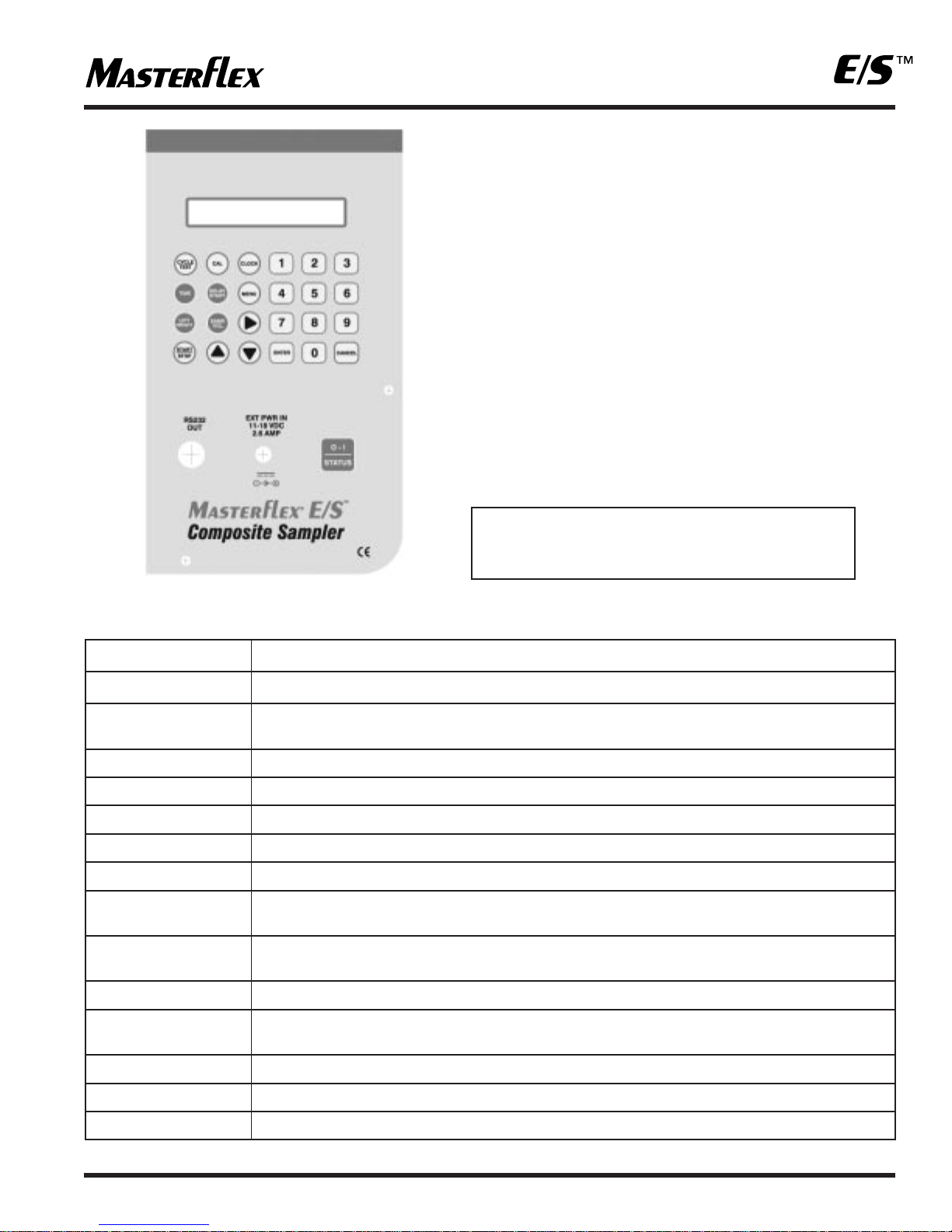
SAMPLER SYSTEM READY
HH:MM:SS MM/DD/YYYY
BATTERY CHARGING
The Composite Sampler is equipped with an internal four
state battery charger capable of diagnosing and automatically
charging the internal battery. The operator only needs to
connect the AC/DC Universal Power Supply/Converter or
Automotive Power Adapter accessory. The sampler system
will automatically power up and begin charging the battery.
After 10 minutes the LCD display on the control console will
power down, going blank. The battery will continue to charge
until it has reached is full potential. Once the battery is fully
charged, the battery will be placed on a float or maintenance
charge until the external power source is disconnected.
The system may run or be programmed while the unit is
charging. Battery charging will continue in the background
while other operations are taking place. Allow a minimum of
8 hours to fully charge the battery from a fully discharged
state with no other operations occurring. During battery
charging all functions of the sampler are operational.
WARNING! The AC/DC Power Supply/Converter
is rated for INDOOR USE ONLY.
DO NOT use the AC/DC Power
Supply/Converter in an outdoor
environment to either charge the
battery or power the drive. Electrical
shock, severe injury and/or death is
possible if this warning is ignored.
SETTING THE TIME AND DATE
Press the keypad's CLOCK key. The display will read:
TIME
The clock used in the Composite Sampler is a 24-hour clock,
does not use an AM or PM notation and shows the time in
an HH:MM:SS format. The clock displays 12:00 AM midnight
as 00:00:00 (the starting point of the clock), 6:00:00 AM as
06:00:00, 12:00:00 PM (or noon) as 12:00:00 and 6:00 PM
as 18:00:00.
If a sample was taken at 3:00 PM the clock will read 15:00:00.
The Composite Sampler clock was set at the factory based
upon our local time. The time is expressed as hour, hour,
minute, minute, second, second. If the current time on the
clock is correct, bypass setting the time by pressing ENTER
or CANCEL and you will be taken to the screen where you
may change the date. See the screen below.
If you need to correct the time shown on the clock, use the
numeric keypad to enter the current time and press ENTER.
The display will change to the date correction screen as
shown below.
DATE:
The calendar date is expressed as month, month, day, day,
year, year.
If the date is correct, press ENTER or CANCEL and you will
be taken back to the system prompt.
If you need to correct the date shown, use the numeric
keypad, enter the date and press ENTER.
EXAMPLE: To enter January 1, 2003, press 10103 on the
numeric keypad and press ENTER.
To enter December 31, 2002, press 123102 on
the numeric keypad and press ENTER.
You will then be taken back to the system prompt screen
which will now display the current time and date.
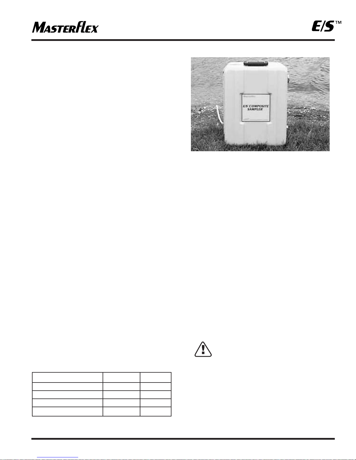
SECURITY
The Composite Sampler will be exposed to an outdoor
environment in which the operator may or may not be
present or in attendance. To protect the unit from tampering
by unauthorized individuals the sampler housing may be
locked using the two locking latches on the exterior of
the housing.
In addition a security feature has been incorporated into
the Composite Sampler to lock the keypad.
SET TIME (HR:MIN:SEC)
20:30:57 (23:59:59)
SET DATE (MON/DAY/YR)
09/21/02 (MM/DD/YY)