Page 4 Page 5
INTRODUCTION
In 2000, CEDAR Audio launched the DNS1000 dynamic noise suppressor. This is
a stand-alone, desktop-format unit designed specifically for film production,
dubbing, outside broadcast (remote) and studio noise suppression.
The format of the DNS1000 is ideal for replacing analogue units that have been in
use for many years, and for use in situations where rapid setup and processing is
required ‘on the fly’. However, it does not offer automation, nor can it be linked to
a digital audio workstation other than by its audio connectors. So we designed
the DNS2000…
The DNS2000 is a combination of a rackmount unit that provides audio I/O and
nearly 200MFLOPS of processing power, plus remote control software for your
Pro Tools host system. With just a single USB control connection between the
DNS2000 hardware and the host, the DNS2000 is very simple and quick to install.
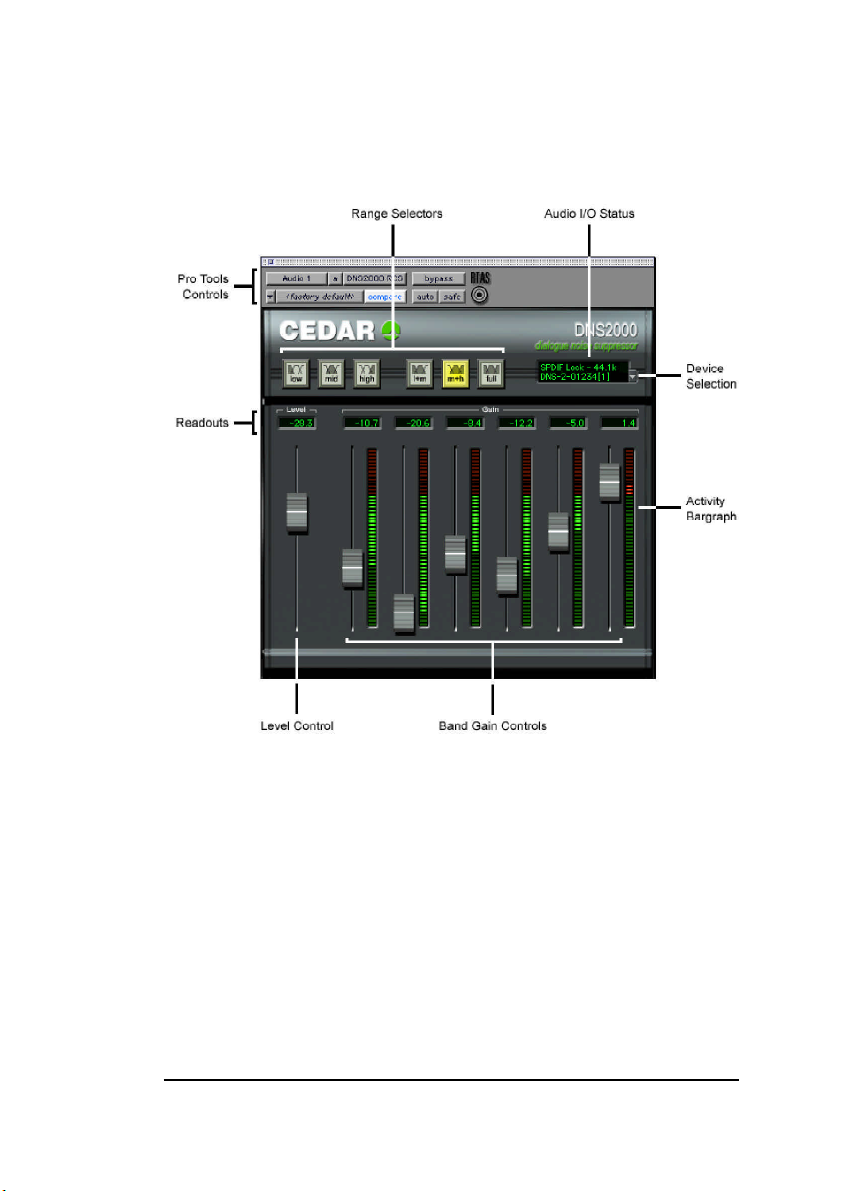
Once you have loaded the DNS2000 remote control software, you can control all
aspects of the DNS2000 from within Pro Tools, and automate all its operating
parameters. Quality, speed and simplicity are paramount considerations in the
DNS2000 design, and its features include the following:
■Near zero latency
The DNS2000 has a group delay of less than 10 samples (typically less
than 1/200th of a frame) so there is no loss of lip-sync when using it.
■Flexibility
The DNS2000 will handle a wide range of noise suppression
requirements.
■Speed and ease of use
The DNS2000 offers a carefully designed user-interface that maximises
speed of use.
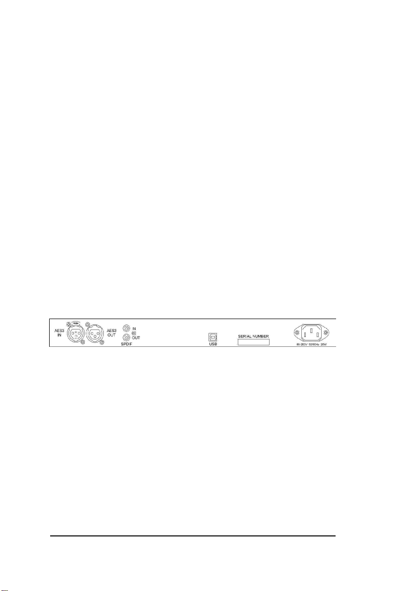
■Audio interfaces
The DNS2000 incorporates a 24-bit digital audio interface conforming to
both AES/EBU and SPDIF standards.
■Universal power supply
Its universal power supply means that a DNS2000 will work anywhere in
the world.
■Powerful processor
A 40-bit floating point DSP processor delivers up to 198MFLOPS so that
the DNS2000 will handle the most complex processing requirements.
HOST SYSTEM REQUIREMENTS
Macintosh OS-X users:
The DNS2000 should be used with Pro Tools version 6 or later. Any Macintosh
with a free USB port running Mac OS-X and a suitable version of Pro Tools will
support the OS-X version of the DNS2000 Remote Control Software and
processor unit.
Macintosh OS9.xx users:
We recommend that the DNS2000 should be used with Pro Tools version 5.1.1 or
later. Any Macintosh with a free USB port running Mac OS 9.xx and a suitable
version of Pro Tools will support the OS9 version of the DNS2000 Remote Control
Software and processor unit.
DNS2000 FIRMWARE
If you intend to use the DNS2000 with a Macintosh running OS-X, the DNS2000
hardware will require version 2 firmware. This is supplied as standard with all
units shipped on or after 1 September 2003. Units originally shipped for use
under OS9.xx and which incorporate version 1 firmware must be upgraded to
version 2. The upgrade software is provided on your DNS2000 installation CD as:
OS 10:Firmware Upgrade:DNS2000 Firmware Upgrade.command
Double-click to run this programme, and follow the on-screen instructions.
If the DNS2000 hardware already has version 2 firmware installed, the
programme will return an error message informing you that there is no need to
upgrade.
ASSUMED KNOWLEDGE
This manual assumes that you are fully conversant with your Macintosh computer
and MacOS, and that you know how to operate your Pro Tools host system. It will
refer to operations that are common to these products, but will not attempt to
explain them.