MTHTrains DCS Proto 2 Sound AIU User manual

Compatibility
This device is compatible with any model railroading accessory or switch
activated by an external power supply or control switch. Consult the individual
item’s operator’s manual for specific instructions on how to operate the
accessory or switch.
PLEASE READ BEFORE USE AND SAVE
ACCESSORY INTERFACE UNIT
OPERATOR’S MANUAL
C
CC
S
SS
D
DD
M
E
T
S
Y
S
D
N
A
M
M
O
C
L
A
T
IG
I
D
M
E
T
S
Y
S
D
N
A
M
M
O
C
L
A
T
IG
I
D
M
E
T
S
Y
S
D
N
A
M
M
O
C
L
A
T
IG
I
D
by mth electric trains

Table of Contents
Introduction To The AIU..................................................................................... 3
Required Tools....................................................................................... 3
Installing The AIU Into The DCS System......................................................... 4
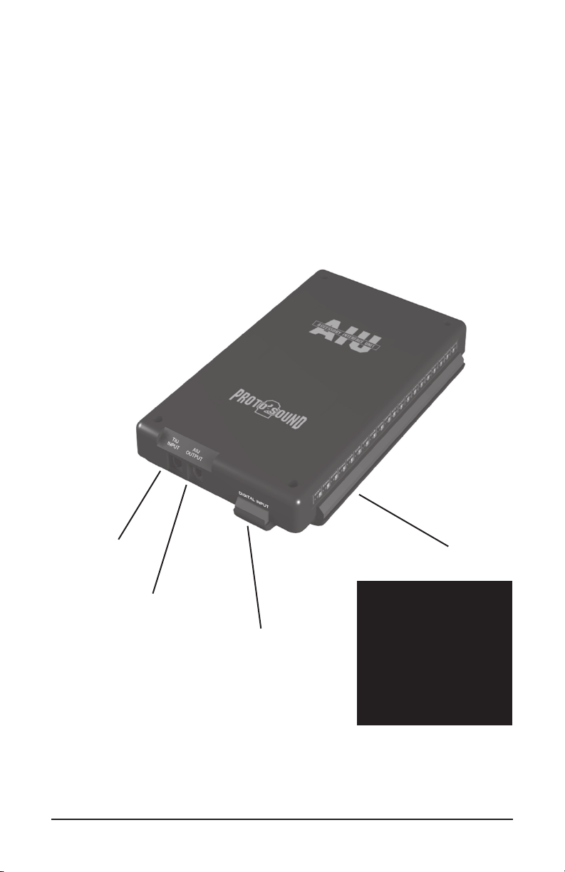
Wiring To The TIU................................................................................ 4
Daisy Chaining AIUs Together.............................................................. 4
Programming AIUs Into The DCS System........................................................ 5
Wiring Accessories And Switches....................................................................... 6
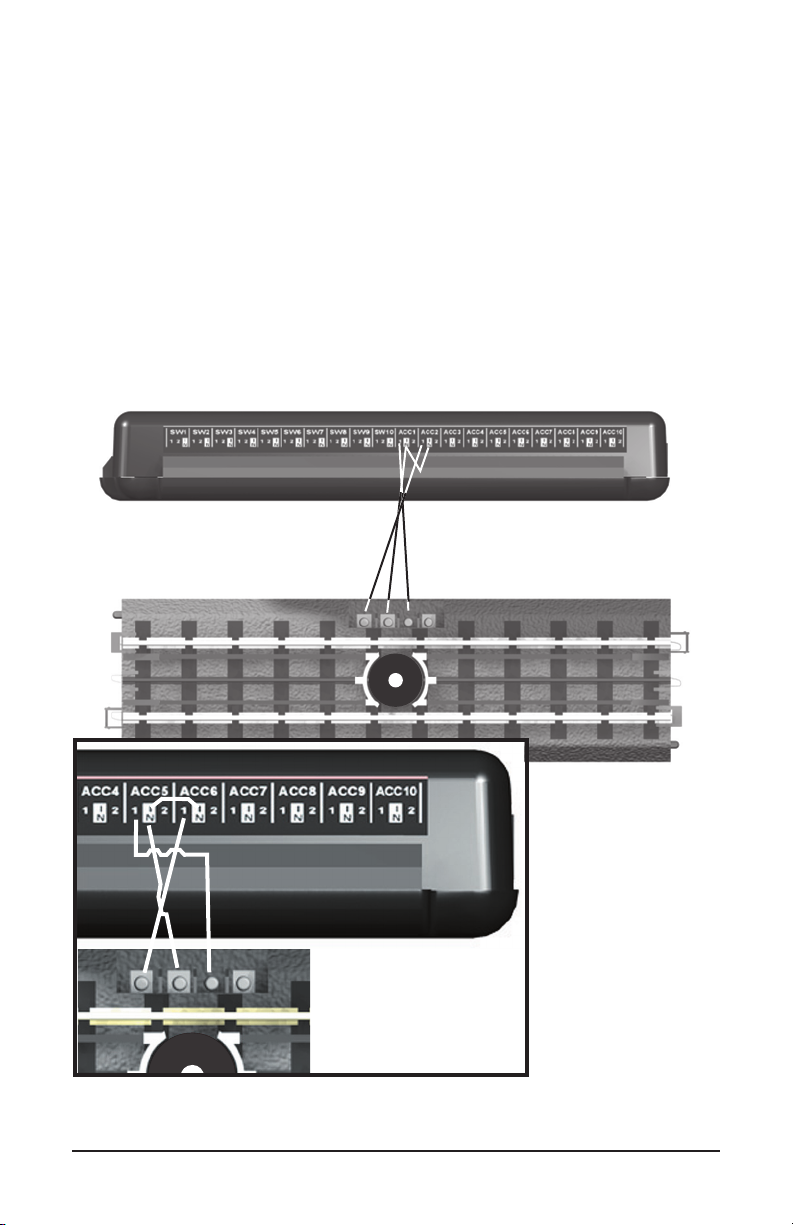
Operating Track Section........................................................................ 6
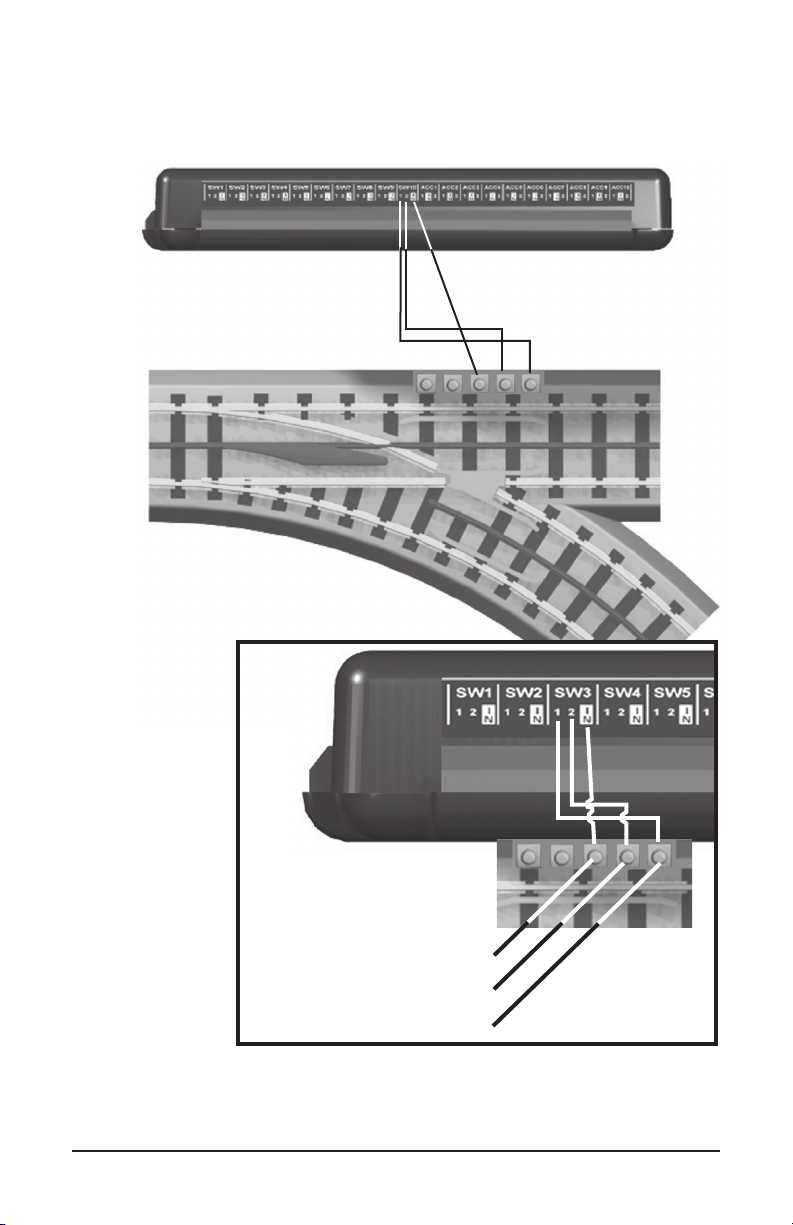
Switches And Turnouts.......................................................................... 7
Accessories With Two Contacts............................................................. 8
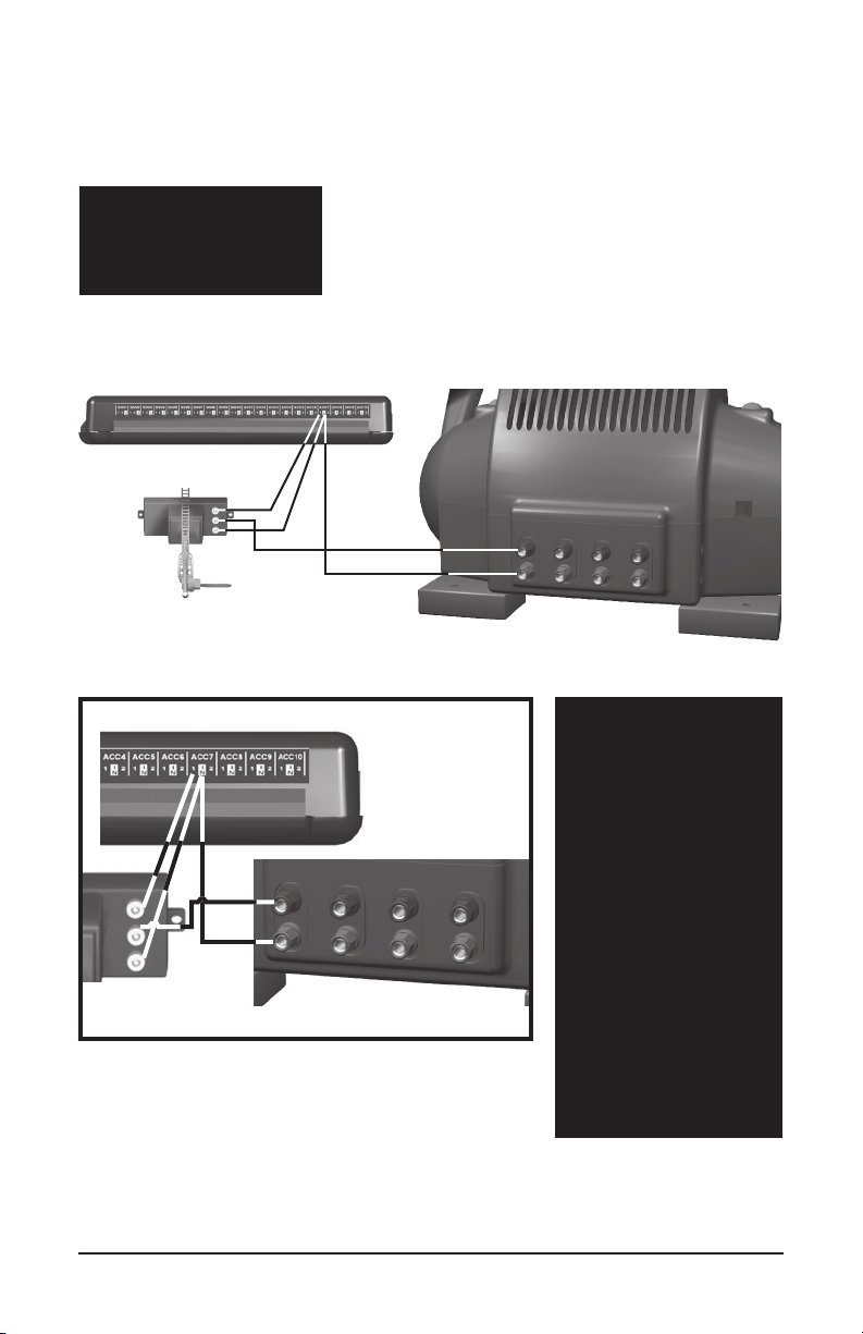
Accessories With Three Contacts.......................................................... 9
Accessories With Four Contacts............................................................ 10
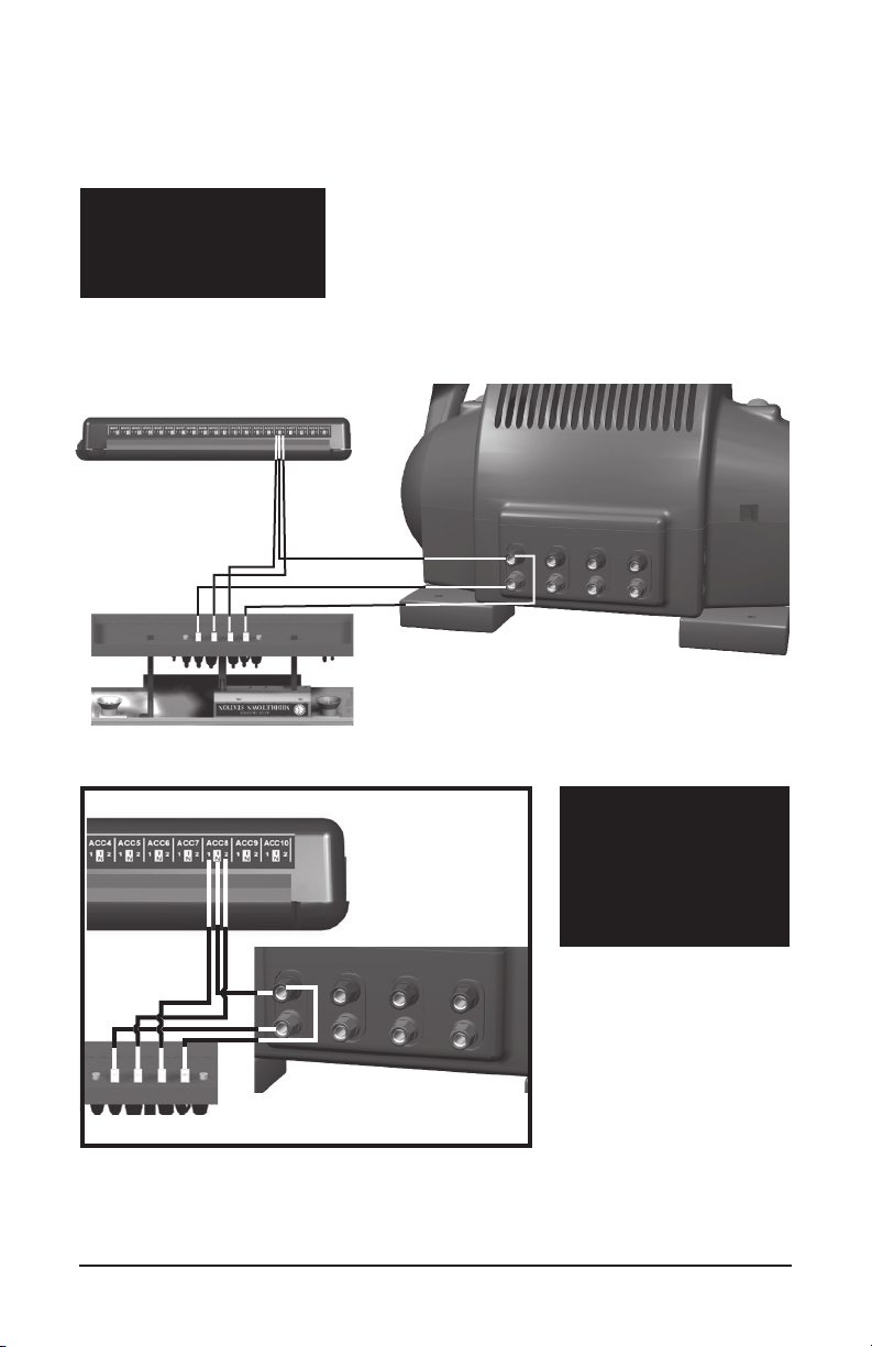
Accessories With Five Contacts............................................................. 11
Programming Individual Accessories And Switches Into The DCS System... 12
Programming Accessories...................................................................... 12
Programming Switches.......................................................................... 15
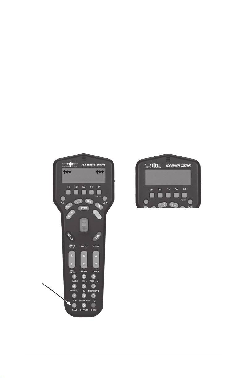
Activating Accessories And Switches................................................................. 17
Troubleshooting AIU Problems...........................................................................19
Service & Warranty Information....................................................................... 20
Limited One-Year Warranty................................................................... 20
CAUTION: ELECTRICALLY OPERATED PRODUCT
Recommended for Ages 14 and up. Not recommended for children under 14 years of age without adult supervision. As
with all electric products, precautions should be observed during handling and use to prevent electric shock.
WARNING: When using electrical products, basic safety precautions should be observed, including the following:
Read this manual thoroughly before using this device.
M.T.H. recommends that all users and persons supervising use examine the hobby transformer and other electronic equipment
periodically for conditions that may result in the risk of fire, electric shock, or injury to persons, such as damage to the primary cord,
plug blades, housing, output jacks or other parts. In the event such conditions exist, the train set should not be used until properly
repaired.
Do not operate your layout unattended. Obstructed accessories or stalled trains may overheat, resulting in damage to your layout.
This train set is intended for indoor use. Do not use if water is present. Serious injury or fatality may result.
Do not operate the hobby transformer with damaged cord, plug, switches, buttons or case.

Introduction To The AIU
The Accessory Interface Unit (AIU) turns the DCS System into a complete
layout control system. Each AIU controls up to 10 accessories and 10 switches
(turnouts) and allows you to control routes and scenes through your remote
control.
The AIU itself is essentially a box of relays that is especially designed to receive
signals from the DCS System. The remote tells the AIU which relay to trigger,
and it sets the accessory or switch into motion.
TIU
Connection
Input
AIU
Connection
Input
(For Daisy Chaining
Multiple AIUs) Digital Input
(For Future Use)
Accessory/Switch
Connection Banks
ACC
IN = Armature of Relay
1 = NO (normally open)
2 = NC (normally closed)
SW
IN = AC Common
1 = Straight
2 = Curved
Required Tools
A flathead jeweler’s screwdriver for wiring into the AIU
DCS Accessory Interface Unit 3

Installing The AIU Into
The DCS System
Once you have completed the wiring and set up instructions below, it is easy to activate
accessories and throw switches using only the thumbwheel and a single softkey. Be
careful to wire each accessory as its instructions dictate, and you will have your system
working in no time.
Wiring To TIU
Plug one end of the AIU/TIU cable (included) into the “TIU Input” port on the AIU and
the other end into the “AIU Input” port of the TIU.
Daisy Chaining AIUs Together
Plug one end of the AIU/TIU cable (included with second AIU) into the “AIU Output”
port of the first AIU (connected to the TIU) and the other end into the “TIU Input” port
of the second AIU.
NOTE: You can daisy
chain up to five AIUs for
each TIU on your layout.
DCS Accessory Interface Unit4

FOUND TIU ADDRESs 1
WITH 1 AIU BOXES
CONNECTED
Programming AIUs Into
The DCS System
Before you can add accessories and switches for activation by DCS, you must first read
all connected AIUs into the system.
With all TIUs and AIUs properly wired and the transformer set to 18v, press READ on
the DCS handheld. The system will automatically locate and add new AIUs to its map.
See the DCS System Operating Instructions for complete instructions on adding and
numbering the TIUs on your system.
INACTIVE ENG
INA S/U ALL
READ
DCS Accessory Interface Unit 5

Wiring Accessories and
Switches
You can wire up to 10 accessories plus 10 switches into each AIU.
Because accessories come in so many different configurations, you should carefully
check the wiring instructions for each specific accessory before connecting to the
AIU. Below are general guidelines to help you complete this wiring.
Operating Track Sections (Wired For Track Power)
DCS Accessory Interface Unit6

Switches/Turnouts
AC Ground
Curved
Straight
DCS Accessory Interface Unit 7

Accessories With Two Contacts
Examples Include:
Lighted Row House
Operating Radar Tower
Operating Rotary Beacon
DCS Accessory Interface Unit8

Accessories With Three Contacts
Examples Include:
Operating Semaphore
Operating Block Signal
NOTE: Accessories
controlled by a track
activation device (TAD)
or infrared track
activation device (ITAD)
can be wired up to the
AIU as well as the TAD
or ITAD. Such a
configuration will allow
the accessory to be
triggered remotely by
the AIU and DCS
remote or via a train on
the track when passing
by the TAD or ITAD.
Wire the accessory to
the AIU as described on
the preceding and
following pages.
DCS Accessory Interface Unit 9

Accessories With Four Contacts
Examples Include:
Operating Passenger
Platform
A
B
C
D
NOTE: To control
lights and operation
separately, you can wire
the lights into one ACC
port and the operation
wires into another.
AB
C
D
DCS Accessory Interface Unit10

Accessories With Five Contacts
Examples Include:
Operating Car Wash
Operating Gas Station
Operating Firehouse
ABCDE
ABCDE
DCS Accessory Interface Unit 11

Programming Individual
Accessories & Switches Into
The DCS System
Programming Accessories
Turn off the power supply, then make sure the accessory has been wired into the
AIU as shown in the preceding examples and according to your accessory’s
instructions.
Power up to 18 volts and press READ on the DCS handheld to add your AIU to
the DCS system (see page 5 for more explanation). Go through the DCS
handheld’s menu as follows:
1. Press the Black MENU button to bring up the four main
menus in the DCS system.
2. Using the thumbwheel,
scroll down the menu list
until you arrive at System.
3. Press the thumbwheel to
enter the System Menu.
Your screen should reveal at
the bottom that you are in
the System Menu.
4. Scroll and select
Accessory Setup from the
available choices in the
System Menu.
5. Scroll and select Add
Accessory from the
available choices in the
Accessory Setup Menu.
MENU
SOUND
CONTROL
SYSTEM
ADVANCED
Press Menu
SOUND
CONTROL
SYSTEM
ADVANCED
SWITCH SETUP
ACCESSORY SETUP
SET REMOTE ADDRESS
MENU: SYSTEM
ADD ACCESSORY
EDIT ACCESSORY
DELETE ACCESSORY
MENU: ACCESSORY SETUP
Scroll and Select System
Scroll and Select
Accessory Setup
Select Add Accessory
DCS Accessory Interface Unit12

AIU
#1
AIU
#2
AIU
#3
AIU
#4
AIU
#5
Programming Accessories (cont'd)
6. Select which TIU
the accessory is wired
to (via the AIU) (See
the TIU Setup section
in the DCS User’s
Manual for how to
number TIUs.)
7. Select which AIU
the accessory is added
to. To determine the
AIU’s number, simply
count out from the
TIU. For instance, if
you have three AIUs, the one connected directly to the TIU
is AIU1, the one connected directly to AIU1 is AIU2, and
the one connected directly to AIU2 is AIU3.
8. Select the AIU port (ACC1-ACC10) the accessory is
wired into.
Select TIU To Use
Select AIU To Use
Select Accessory #
Select Characters For
Accessory Name
(Highlighted by Brackets)
1
2
3
SEL TIU TO USE
1
2
3
SEL AIU TO USE
ACC !
ACC 2
ACC 3
SEL ACCESSORY #
[A]BCDEFGHIJKLMNO
PQRSTUVWXYZ#- &
O123456789<D
ENTER ACCESS NAME
DCS Accessory Interface Unit 13

Programming Accessories (cont'd)
10. You may give the accessory a name up to 16
characters long. Select the “D” at the end of the
character set to signify that you are done with this
function.
11. The accessory will now show up, by the name
you have assigned, on the accessory screen when
you press the DCS handheld’s ACC button.
See the DCS System Operating Instructions for complete
instructions on editing and renaming accessories and for
instructions on adding and numbering TIUs.
Select Characters For
Accessory Name
Select the "D"
Character To Enter
Name For Accessory
Accessory Name As Seen
In The Accessory List
[A]B[C]DEFGHIJKLMNO
PQRSTUVWXYZ#- &
O123456789<D
car w
ABCDEFGHIJKLMNO
PQRSTUVWXYZ#- &
O123456789<[D]
car wash
!: car wash
2: Gas Station
3: Firehouse
ALL S/U ON OFF ACT
DCS Accessory Interface Unit14

Programming Switches
Turn off the power supply, then make sure the switch has been wired into the AIU as
shown in the preceding examples and according to your switch’s instructions.
Power up to 18 volts and press READ on the DCS handheld to add your AIU to the DCS
system (see page 5 for more explanation). Go through the DCS handheld’s menu as
follows:
1. Wire the switch into the AIU as shown in the AIU user’s manual and your track’s
instructions.
2. Go through the DCS handheld’s menu as follows:
3. Select which TIU the switch is wired to (via the AIU).
A. Press Menu Button
B. Select System
C. Select Switch Setup
D. Select Add Switch
MENU
SOUND
CONTROL
SYSTEM
ADVANCED
Press Menu
SOUND
CONTROL
SYSTEM
ADVANCED
Scroll and Select System
Scroll and Select
Switch Setup
SWITCH SETUP
ACCESSORY SETUP
SET REMOTE ADDRESS
MENU: SYSTEM
ADD SWITCH
EDIT SWITCH
DELETE SWITCH
MENU: SWITCH SETUP
1
2
3
SEL TIU TO USE
Select Add Switch
Select TIU To Use
DCS Accessory Interface Unit 15

4. Select which AIU the switch is added to. (See the
explanation for counting AIUs in the Programming
Accessories section on page 13.)
5. Select the AIU port (SW1-SW10) the switch is
wired into.
Programming Switches (con'd)
Select AIU To Use
Select Switch #
Select Characters For
Accessory Name
(Highlighted By Brackets)
Select TIU To Use
1
2
3
SEL AIU TO USE
SW !
SW 2
SW 3
SEL SWITCH #
[A]BCDEFGHIJKLMNO
PQRSTUVWXYZ#- &
O123456789<D
ENTER ACCESS NAME
!: siding switch 1
2: siding switch 2
3: yard switch 1
ALL S/U
6. The LCD prompts you to name the switch, and an
alphanumeric character set is displayed. Use the
thumbwheel to scroll through the character set, and
when the character you want to type next is bracketed,
press the thumbwheel to select it. You may give the
switch a name up to 16 characters long. Select the “D”
at the end of the character set to signify that you are
done with this function (See page 13 - 14 for more
informationon naming accessories).
The switch will now show up, by the name you have
assigned, on the switch screen when you press the DCS
handheld’s SW button.
See the DCS System Operating Instructions for complete
instructions on editing and renaming switches and for
instructions on adding and numbering TIUs.
DCS Accessory Interface Unit16

Activating Accessories And
Switches
Once you have completed the wiring, mapping, and naming steps, you can easily activate
an accessory or switch.
1. Press the handheld’s ACC (for accessory control) or SW (for switch control)
button.
2. Scroll the thumbwheel until the arrow points to the accessory or switch you want
to activate.
3. Press the softkey under the option you choose (see below for options).
For accessories the softkey options are ALL, S/U, ON, OFF, ACT. ALL triggers all
accessories connected to any TIU and receiving track power. S/U takes you to the
handheld’s setup menu, where you can add, edit, or delete an accessory. ON turns
accessories on for continuous operation until you turn them off. OFF turns accessories
off. ACT activates accessories for single, not continuous, operation.
!: car wash
2: Gas Station
3: Firehouse
ALL S/U ON OFF ACT
ON
ACCESSORY
1: car wash
Scroll To Select
Press Softkey Option
ACC
or
SW
!: ABC
2: Gas Station
3: Firehouse
ALL S/U ON OFF ACT
Press ACC or SW
DCS Accessory Interface Unit 17

For switches the softkey options are ALL, S/U,
ñ or ö ALL triggers all switches connected to
any TIU and receiving track power to move into
the position you select. S/U takes you to the
handheld’s setup menu, where you can add, edit,
or delete a switch. ñ throws the switch straight.
ö throws the switch curved.
NOTE: Unlike with engines, the ALL button for
accessories and switches does not distinguish
between active and inactive. The button activates
every accessory or switch that is connected to a
TIU and receiving track power.
Activating Accessories & Switches (con'd)
!: siding switch 1
2: siding switch 2
3: yard switch 1
ALL S/U
DCS Accessory Interface Unit18

Accessory/Switch Doesn't Activate
AIUs Don't Respond
Switch Sticks
Remedy
Remedy
Remedy
Remedy
When I activate the accessory/switch from
the handheld, nothing happens, or the
wrong accessory/switch activates.
I have multiple AIUs daisy chained
together, but the accessories on the last
AIUs in the chain do not activate properly.
The switch opens but won't close.
Make sure you are using the AIU/TIU
cables included with the AIUs. While
other cables may look similar, they may
cause voltage drop and drain off too much
power for the signal to reach the outer
AIUs.
There is no reason the AIU should
cause this. Check your switch and
wiring for defects. (See Page 7)
Check to make sure the accessory/switch
is mapped correctly in the handheld. The
DCS system knows only to activate
whatever is wired into the AIU and port
you map, so a mis-mapped model will not
activate.
Troubleshooting DCS AIU Problems
Although DCS has been designed and engineered for ease of use, you may have
some questions during initial operation. The following table should answer most
questions. If your problem cannot be resolved with this table, visit the MTH
Proto-Sound web site for more information and instructions for contacting MTH
for direct service.
www.protosound2.com
DCS Accessory Interface Unit 19

Service & Warranty Information
Limited One-Year Warranty
M.T.H. products purchased within one year from the date of manufacture are warrantied
against defects in material or workmanship, excluding wear items such as light bulbs, pick-up
rollers, batteries, smoke unit wicks, and traction tires. M.T.H. Authorized Retailers will
replace, refund, or credit the defective item if:
- The item was manufactured within the previous year
- It was purchased from M.T.H. directly by an M.T.H. Authorized Retailer or directly from
an M.T.H. Distributor by an M.T.H. Authorized Retailer
IMPORTANT NOTE: This warranty does not cover damages caused by improper care,
handling, or use. Transportation costs incurred by the customer are not covered under this
warranty.
Purchases from eBay or other online auction or selling sites will NOT be covered under
warranty unless the seller is an M.T.H. Authorized Retailer.
See our website at www.mthtrains.com to identify an M.T.H. Authorized Retailer near you.
This warranty gives you specific legal rights, and you may have other rights that vary from
state to state. Specific questions regarding the warranty may be forwarded to M.T.H. directly.
M.T.H. Electric Trains
6660 Santa Barbara Road, Suite 20
Elkridge, MD 21075
How to Get Service Under the Terms of the
Limited One-Year Warranty
This item carries a one-year warranty from the date of manufacture for the M.T.H.
Authorized Retailer who sold the product. The defective item should be returned to the
dealer where purchased.
If the dealer has trained service techs, they can offer to repair the item (M.T.H. will supply
warranty parts as needed free of charge. If parts are not available a refund will be given to
the dealer).
M.T.H. will no longer provide repair service on any products at its corporate headquarters.
If an item is defective and cannot be repaired, it needs to be returned to the original
purchasing dealer and the end-user can obtain a refund from the retailer. The original
purchasing dealer will then return the item to M.T.H. for credit.
Customers may want to request that their items are tested by the retailer prior to taking the
item home. All items are tested by M.T.H. Electric Trains prior to shipment from our
production facilities.
This manual suits for next models
1
Table of contents
Other MTHTrains Recording Equipment manuals
Popular Recording Equipment manuals by other brands

Alesis
Alesis QUADRAVERB Reference manual

Philips
Philips IS 5022 PROFESSIONAL Mark II instruction manual

Lectrosonics
Lectrosonics SPNCWB Installation and startup guide

Eventide
Eventide INSTANT FLANGER MK II FL201 instruction manual

Harman
Harman Crown DSi 8Mn Operation manual

Elkron
Elkron IT500F Installation booklet