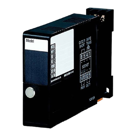
M-system R3-GM1 User manual

R3-GM1
P. 1 / 6EM-8463 Rev.1
MODBUS INTERFACE MODULE MODEL R3-GM1
INSTRUCTION MANUAL
BEFORE USE ....
Thank you for choosing M-System. Before use, please check
contents of the package you received as outlined below.
If you have any problems or questions with the product,
please contact M-System’s Sales Office or representatives.
■PACKAGE INCLUDES:
Network interface module ........................................... (1)
Terminating resistor (110Ω, 0.25W) ............................ (1)
■MODEL NO.
Confirm Model No. marking on the product to be exactly
what you ordered.
■INSTRUCTION MANUAL
This manual describes necessary points of caution when
you use this product, including installation, connection and
basic maintenance procedures.
POINTS OF CAUTION
■CONFORMITY WITH EC DIRECTIVES
•The equipment must be mounted inside the instrument
panel of a metal enclosure.
•Theactualinstallationenvironmentssuchaspanelcon-
figurations, connected devices and connected wires may
affect the protection level of this unit when it is integrated
in a panel system. The user may have to review the CE
requirements in regard to the whole system and employ
additional protective measures to ensure CE conformity.
■UNPLUGGING THE MODULE
Before you remove the module from its base or mount it,
turn off the power supply for safety.
■ENVIRONMENT
•Indooruse
•Whenheavydustormetalparticlesarepresentintheair,
install the unit inside proper housing with sufficient ven-
tilation.
•Donotinstalltheunitwhereitissubjectedtocontinuous
vibration.Donotsubjecttheunittophysicalimpact.
•Environmentaltemperaturemustbewithin-10to+55°C
(14to131°F)withrelativehumiditywithin30to90%RH
in order to ensure adequate life span and operation.
■WIRING
•Do not install cables (power supply, input and output)
close to noise sources (relay drive cable, high frequency
line, etc.).
•Do not bind these cables together with those in which
noisesarepresent.Donotinstalltheminthesameduct.
■AND ....
The unit is designed to function as soon as power is sup-
plied, however, a warm up for 10 minutes is required for sat-
isfying complete performance described in the data sheet.
INSTALLATION
Use the Installation Base Model: R3-BSx, or Model: R3-
BSWx for free I/O address capability.
Before mounting the Network Interface Module R3-GM1
onto the base, be sure to configure the module as explained
below.
■DATA ALLOCATION
UsethesideDIPSW1tosetthenumberofslotswhichthe
module is assigned to.
See“TRANSMISSIONDATADESCRIPTIONS.”
■NODE ADDRESS & BAUD RATE
See“COMPONENTIDENTIFICATION.”
■NETWORK SLOTS ON THE BASE
WithModelR3-BSxbase,mounttheI/OModulesfromthe
left end (I/O 1) to the right in order that the Network Mod-
ule assigns data areas from I/O 1.
Network Module(s) and Power Module are mounted basi-
cally at the right end though technically they could be
mounted in any position.
WithModelR3-BSWxbase,thereisnolimitationinmount-
ing positions as I/O address can be assigned freely to each
module using rotary switches equipped on the base.
It is available to assign the module to max. 8 slots. The as-
signed slots numbers can not be used again for the real I/O
moduleswhichneedtobemountedonthesamebase.Don’t
set the interface module for more than 16 slots as it can not
read the data for more than 16 modules.
I/O 1 I/O 2 I/O n


R3-GM1
P. 2 / 6EM-8463 Rev.1
COMPONENT IDENTIFICATION
SW3
SA1
SA2
ON
4
3
2
1
ON
8
7
6
5
4
3
2
1
SW1
1
2
3
4
5
6
5
4
3
2
1
0
9
8
7
6
5
4
3
2
1
0
9
8
7
6
SW6
ON
8
7
6
5
4
3
2
1
FG
SLD
DG
DB
DA
■SIDE VIEW■FRONT VIEW
Node Address Setting
Rotary SW, upper digit
ERR LED
Configuration Jack
Terminal Block
RUN LED
Data
Parity
Transfer
Rate
Transmisson
Properties
LED
Module
Allocation
Node Address Setting
Rotary SW, lower digit Functions
■FRONT SW
• Node Address:SA1,SA2
Set the module’s node address in hexadecimal.
• Transfer Rate: SW6
SW TRANSFER RATE (bps)
38.4 k 19.2 k 9600 4800
SW6-1 OFF(*) ON OFF ON
SW6-2 OFF(*) OFF ON ON
• Parity:SW6*1
SW PARITY
NONE (*)ODD EVEN N/A
SW6-3 OFF(*) ON OFF ON
SW6-4 OFF(*) OFF ON ON
• Data Mode:SW6*1
SW DATA MODE
RTU (Binary) ASCII
SW6-5 OFF(*) ON
*1.Bitassignmenttoonebytedataisshownasbelowbased
onParityandDataModesetting.
Modbus STA R T DATA PARITY STOP
RTU
MODE
1 8 1 1
1 8 None 2
ASCII
MODE
1 7 1 1
1 7 None 2
■SIDE DIP SW
• Module Allocation: SW1
MODULE SW1-1 SW1-2 SW1-3
1OFF(*) OFF(*) OFF(*)
2 ON OFF OFF
3OFF ON OFF
4 ON ON OFF
5OFF OFF ON
6ON OFF ON
7OFF ON ON
8ON ON ON
• LED Function: SW3
Functionsassigned to the front RUNand ERR LEDs can
be selected.
SW3-4 LED
RUN ERR
OFF(*) Greenwhennormal Green
/flashes when abnormal
ON Redwhenreceiving Redwhentransmitting
(*) Factory setting

R3-GM1
P. 3 / 6EM-8463 Rev.1
1
2
3
4
5
6
130 (5.12)
27.5 (1.08) 109 (4.29)
POSITIONING
GUIDE
TERMINAL
COVER
6–M3
SCREW
6.2
(.24)
WIRING INSTRUCTIONS
3.2 (.13) dia.
4 min.
(.16)
12 (.47) max.
6 max.
(.24)
3 (.12) max.
TERMINAL CONNECTIONS
Connect the unit as in the diagram below.
INTERNAL POWER
INTERNAL
COMM. BUS
FG
SLD
DG
DB
DA
1
4
RUN +
RUN –
BUS CONNECTOR
RUN CONTACT OUTPUT
CONFIGURATION JACK JACK
To Other
Modbus
Devices
■ DIMENSIONS mm (inch)
■CONNECTION DIAGRAM
■ SOLDERLESS TERMINAL mm (inch)
Refer to the drawing below for recommended ring tongue
terminal size. Spade tongue type is also applicable. Solder-
lessterminalswithinsulationsleevedonott.Applicable
wire size: 0.75 to 1.25 mm2
Tx +/Rx +
Tx –/Rx –
SG
Rx+
Rx−
HOST PC
DA
DB
DG
SLD
FG
R3-GM1
DA
DB
DG
SLD
FG
R3-GM1
FG FG
TERMINATOR
COMMUNICATION CABLE CONNECTIONS

R3-GM1
P. 4 / 6EM-8463 Rev.1
Modbus FUNCTION CODE
■ Data and Control Functions
CODE NAME R3-GM1
01 ReadCoilStatus Digitaloutputfromtheslave
02 ReadInputStatus XStatus of digital inputs to the slave
03 ReadHoldingRegisters XGeneralpurposeregisterwithintheslave
04 ReadInputRegisters XCollected data from the field by the slave
05 ForceSingleCoil Digitaloutputfromtheslave
06 PresetSingleRegisters XGeneralpurposeregisterwithintheslave
07 ReadExceptionStatus
08 Diagnostics X
09 Program484
10 Poll484
11 FetchComm.EventCounter Fetchastatuswordandaneventcounter
12 FetchComm.EventLog Astatusword,aneventcounter,amessagecountand
a field of event bytes
13 ProgramController
14 PollController
15 ForceMultipleCoils XDigitaloutputfromtheslave
16 PresetMultipleRegisters XGeneralpurposeregisterwithintheslave
17 ReportSlaveID Slavetype/‘RUN’status
18 Program884/M84
19 ResetComm.Link
20 ReadGeneralReference
21 WriteGeneralReference
22 MaskWrite4XRegister
23 Read/Write4XRegisters
24 ReadFIFOQueue
■ Exception Codes
CODE NAME R3-GM1
01 IllegalFunction XFunctioncodeisnotallowablefortheslave
02 IllegalDataAddress XAddressisnotavailablewithintheslave
03 IllegalDataValue XDataisnotvalidforthefunction
04 SlaveDeviceFailure X
05 Acknowledge X
06 SlaveDeviceBusy X
07 NegativeAcknowledge X
08 MemoryParityError
■ Diagnostic Subfunctions
CODE NAME R3-GM1
00 ReturnQueryData XLoopbacktest
01 RestartComm.Option XResettheslaveandclearallcounters
02 ReturnDiagnosticRegister XContents of the diagnostic data (2 bytes)
03 ChangeASCIIInputDelimiter XDelimitercharacterofASCIImessage
04 ForceListenOnlyMode XForcetheslaveintoListenOnlyMode

R3-GM1
P. 5 / 6EM-8463 Rev.1
ADDRESS DATA TYPE DATA MODULE POSITION
Input (1X) 1025 – 1032 Module Status
InputRegisters(3X) 1 – 16 I AnalogInput 1
17 – 32 2
33 – 48 3
49–64 4
65 – 80 5
81–96 6
97–112 7
113 – 128 8
257 – 272 F AnalogInput 1
273 – 288 2
289–304 3
305 – 320 4
321 – 336 5
337 – 352 6
353 – 368 7
369–384 8
HoldingRegisters(4X) 1 – 16 I AnalogOutput 1
17 – 32 2
33 – 48 3
49–64 4
65 – 80 5
81–96 6
97–112 7
113 – 128 8
257 – 272 F AnalogOutput 1
273 – 288 2
289–304 3
305 – 320 4
321 – 336 5
337 – 352 6
353 – 368 7
369–384 8
■DATA TYPE
I:Integer,0–10000(0–100%)
F:Floating(32-bitdatacannotbeaccessedviaoatingaddresses.)
Note:DONOTaccessaddressesotherthantheonesmentionedabove.Suchaccessmaycauseproblemssuchasmalfunc-
tion.
• Module Status
Module Status indicates whether individual I/O module is mounted or not. The bit corresponding to the mounted slots turns
to“1,”andtheunmountedslotsto“0.”
Modbus I/O ASSIGNMENTS

R3-GM1
P. 6 / 6EM-8463 Rev.1
M-SYSTEM WARRANTY
M-System warrants such new M-System product which it manufactures to be free from defects in materials and workmanship during the 36-month period following the date that such
product was originally purchased if such product has been used under normal operating conditions and properly maintained, M-System’s sole liability, and purchaser’s exclusive
remedies, under this warranty are, at M-System’s option, the repair, replacement or refund of the purchase price of any M-System product which is defective under the terms of this
warranty. To submit a claim under this warranty, the purchaser must return, at its expense, the defective M-System product to the below address together with a copy of its original
sales invoice.
THIS IS THE ONLY WARRANTY APPLICABLE TO M-SYSTEM PRODUCT AND IS IN LIEU OF ALL OTHER WARRANTIES, EXPRESS OR IMPLIED, INCLUDING ANY IMPLIED
WARRANTIES OF MERCHANTABILITY OR FITNESS FOR A PARTICULAR PURPOSE. M-SYSTEM SHALL HAVE NO LIABILITY FOR CONSEQUENTIAL, INCIDENTAL OR
SPECIAL DAMAGES OF ANY KIND WHATSOEVER.
M-System Co., Ltd., 5-2-55, Minamitsumori, Nishinari-ku, Osaka 557-0063 JAPAN, Phone: (06) 6659-8201, Fax: (06) 6659-8510, E-mail: info@m-system.co.jp
■MODULE STATUS
Module Status indicates whether individual I/O module is
mounted or not, normal or not.
■ANALOG INPUT/OUTPUT DATA
0
15
Card 1 (Slot 1)
Card 2 (Slot 2)
Card 3 (Slot 3)
Card 8 (Slot 8)
0
15
16 bits binary data
TRANSMISSION DATA DESCRIPTIONS
INPUT/OUTPUT DATA
UsetheDIPSWlocatedatthesideofthemoduletospecifymoduleallocation.
1 module is equivalent to 1 I/O module with 16 words analog input and 16 words analog output. Max. 8 modules (128 words
input,128wordsoutput)transmissionisavailable.R3-GM1seemsasifmax.8I/Omodulesaremountedto8slotsviaMod-
bus.
The input of the module is processed as follows.
Inrespondingtotheinput,theoutput(HoldingRegister)commandbecomesvalidviaModbuscommunication,andtheinput
(InputRegister)commandisvalidintheoutput.
Note:Donotmountanymodulesintheslotswhichareoccupiedbyvirtualmodules.IfarealI/Omoduleismountedinthe
slot,aninternalbuserroroccursandtheERRLEDturnson.Max.16realI/Omodulesandvirtualmodulesareavailable.
The interface module can not read the data for more than 16 modules.
■ WHEN R3-GM1 IS MOUNTED TO SLOT 2 (4 modules)
Inpractice,I/Omodulesaremountedtoslot1andslot2.TheR3-NC1inslot7recognizestheR3-SV4inslot1directly.
However,theR3-NC3recognizestheR3-GM1inslot2asif4modulesaremountedtofromslot2to5.
12345678
R3-
SV4
R3-BS08
R3-
GM1
R3-
NC3
R3-
PS1
Modbus Communication R3-GM1 Module R3 Base R3 Communication Module
SLOT REAL MODULE VERTUAL MODULE DATA
Slot 1 R3-SV4 R3-SV4 4 Words
Slot 2 R3-GM1 R3-GM1(1/4) 16 Words
Slot 3 No module R3-GM1(2/4) 16 Words
Slot 4 No module R3-GM1(3/4) 16 Words
Slot 5 No module R3-GM1(4/4) 16 Words
Slot 6 No module No module -
Slot 7 R3-NC3 R3-NC3 -
Slot 8 R3-PS1 R3-PS1 -
Table of contents
Other M-system Recording Equipment manuals

M-system
M-system M8BS2-161 User manual

M-system
M-system M8BS2-164 User manual

M-system
M-system R3 Series User manual

M-system
M-system EtherCAT R3-NECT1 User manual

M-system
M-system Mini-M M2SES2 User manual

M-system
M-system Mini-M M2SES User manual

M-system
M-system R3-NM1 User manual

M-system
M-system M8BS2-162 User manual

M-system
M-system M8BS2-042 User manual

M-system
M-system R3-GE1 User manual