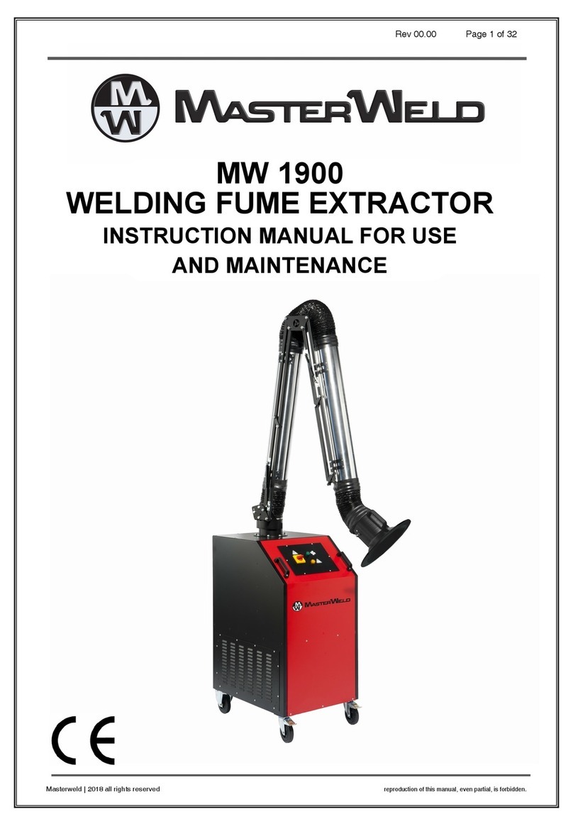
Masterweld MW1901 Instruction manual

MW 1901
Page 1 of 34
©| AES Industrial Supplies Ltd | 2019 all rights reserved reproduction of this manual, even partial, is forbidden.
INSTRUCTION MANUAL
FOR USE
AND MAINTENANCE
MW1901

MW 1901
Page 2 of 34
©| AES Industrial Supplies Ltd | 2019 all rights reserved reproduction of this manual, even partial, is forbidden.
Index
By
Description
0
Analytical index of the operating and maintenance manual
Index..........................................................................................................................................2
Analytical index of the operating and maintenance manual ..................................................2
Scope of the operating and maintenance manual .......................................................................4
Storage of the instruction manual ..............................................................................................5
Updating of the Instruction Manual............................................................................................5
Glossary and pictograms ............................................................................................................6
Manufacturer’s identification data...........................................................................................10
Machine identification and data plates (if they are present) .....................................................11
Declarations.............................................................................................................................11
Guarantee activation form (with repairs by authorised centres)................................................13
General description of the machine ..........................................................................................14
Technical data of the MW1901 T unit.....................................................................................16
Technical data of the MW1901 H unit.....................................................................................17
Description of machine components.....................................................................................18
INSTALLATION..........................................................................................................................19
Mounting and fixing the equipment.......................................................................................19
Reverse the orientation...........................................................................................................22
Electrical connections ...............................................................................................................24
Electrical protection panel......................................................................................................26
MAINTENANCE OF THE MACHINE .............................................................................................27
Replacement of the filters.......................................................................................................27
Detail of filters present in the Depurator with rigid pockets MW1901 T .. Error! Bookmark not
defined.
Detail of filters present in the HEPA rigid pockets Purifier MW1901 H.... Error! Bookmark not
defined.
Malfunctions............................................................................................................................30
Programmed Maintenance Table............................................................................................31
OPERATOR NOTES....................................................................................................................32

MW 1901
Page 3 of 34
©| AES Industrial Supplies Ltd | 2019 all rights reserved reproduction of this manual, even partial, is forbidden.
Detail of maintenance operations of the equipment.............................................................32
SPARE FILTERS..................................................................................Error! Bookmark not defined.
Filter Codes ....................................................................................Error! Bookmark not defined.

MW 1901
Page 4 of 34
©| AES Industrial Supplies Ltd | 2019 all rights reserved reproduction of this manual, even partial, is forbidden.
INTRODUCTION
By
Description
1
Scope of the operating and maintenance manual
This instruction manual is an integral part of the machine and has the purpose of providing all the necessary information
for the following purposes:
•Raise the awareness of operators as regards safety matters;
•Safe handling of the machine when packaged and unpackaged;
•Correct installation of the machine;
•Thorough knowledge of the machine’s operations and limits;
•Correct use in total safety;
•Correct and safe maintenance;
•Dismantling of the machine in total safety, in compliance with the regulations in force on the health and safety
of workers and the environment.
The people in charge of the company’s departments in which this machine will be installed must, according to the
regulations in force, carefully read the content of this Operating Manual and ensure that operators and maintenance
staff operating and working on the machine read the relevant parts.
The time dedicated to this will be fully rewarded by the correct and safe operation of the machine.
This document is based on the assumption that the systems in which the machine is to be installed are in compliance
with the health and safety at work regulations in force.
The instructions, drawings and documentation contained in this Manual are of a technical confidential nature and are
property of the manufacturer; they may not be reproduced in any way, in part of fully.
If this manual is amended by the manufacturer, the Customer has the responsibility of ensuring that only the updated
versions are available in the points of use.

MW 1901
Page 5 of 34
©| AES Industrial Supplies Ltd | 2019 all rights reserved reproduction of this manual, even partial, is forbidden.
INTRODUCTION
By
Description
2
Storage of the instruction manual
The instruction manual must be kept safely and must be handed over to new owners in case of sale throughout the
lifecycle of the machine.
To help preserve the manual in good condition it must be handled with care and with clean hands, and it must not be
placed on dirty surfaces.
It is forbidden to remove, tear out or arbitrarily modify any parts of the manual.
The manual must be stored in an environment away from humidity and heat, in a position near the machines to which
it refers.
Upon the User’s request the Manufacturer shall supply other copies of the machine’s instruction manual.
INTRODUCTION
By
Description
3
Updating of the Instruction Manual
The manufacturer reserves the right to modify the project and improve the machine without informing customers and
without updating the manual already delivered to the User.
If modifications are made to a machine installed at the customer’s premises, in agreement with the manufacturer, and
which entail the amendment of one or more chapters of the manual, the manufacturer shall send the amended chapters
to the holders of the Instruction Manual and its new overall revision.
According to the instructions that will accompany the updated documentation, the User shall replace the old chapters
in the copies held with the new ones, as well as the first page and table of contents with the new revision level.

MW 1901
Page 6 of 34
©| AES Industrial Supplies Ltd | 2019 all rights reserved reproduction of this manual, even partial, is forbidden.
INTRODUCTION
By
Description
4
Glossary and pictograms
This paragraph lists some terms which are not commonly used or with a meaning different from the common one. The
meaning of the abbreviations and pictograms used is described below. The abbreviations and pictograms are used to
indicate operator qualifications and state of the machine; they provide, in a quick and univocal manner, the information
necessary for the correct and safe use of the machine.
GLOSSARY (Annex I point. 1.1.1 Dir. 2006/42/EC)
HAZARD
A potential source of injury or damage to health;
DANGER AREA
Any zone within and/or around machinery in which a person is subject to a risk to his health or safety;
EXPOSED PERSON
Any person wholly or partially in a danger zone;
OPERATOR
The person or persons installing, operating, adjusting, maintaining, cleaning, repairing or moving machinery;
RISK
A combination of the probability and the degree of an injury or damage to health that can arise in a hazardous situation;
GUARD
A part of the machinery used specifically to provide protection by means of a physical barrier;
PROTECTIVE DEVICE
A device (other than a guard) which reduces the risk, either alone or in conjunction with a guard;
INTENDED USE
The use of machinery in accordance with the information provided in the instructions for use;
REASONABLY FORESEEABLE MISUSE
The use of the machinery in a way not intended in the instructions for use, but which may result from readily predictable
human behaviour.
OTHER DEFINITIONS
MAN-MACHINERY INTERACTION
Any situation in which the operator interacts with machinery in any of the operating phases during the lifecycle of the
machinery.
OPERATOR QUALIFICATIONS
Minimum level of skill that an operator must have to carry out the described operation.

MW 1901
Page 7 of 34
©| AES Industrial Supplies Ltd | 2019 all rights reserved reproduction of this manual, even partial, is forbidden.
NUMBER OF OPERATORS
The suitable number of operators, able to carry out the operation described in an optimal way, as established by
a careful manufacturer analysis, whereby a different number of operators might not make it possible to obtain the
expected result or might endanger the safety of the personnel involved.
STATE OF THE MACHINE
The state of the machine includes operating modes, for example automatic running mode, jog command, stop, etc., the
condition of the safety devices on the machines such as protection devices provided (or not provided), pressed
emergency button, type of isolation from energy sources, etc.
RESIDUAL RISK
Risks that persist despite the adoption of the protective measures included in the design of the machine and despite
the additional protective devices and measures adopted.
SAFETY DEVICE
Device:
-That carries out a safety function;
-which, when faulty and/or broken, endangers the safety of people.
(e.g. lifting equipment; fixed, mobile, adjustable protective device, etc., electric, electronic, optical, pneumatic,
hydraulic device interlocking a protection device, etc.).
PICTOGRAMS
The descriptions that follow this pictogram contain:
very important information/instructions, in particular as regards safety.
Failure to respect them may lead to:
•danger for the safety of the operators;
•loss of contractual guarantee;
•waiver of the manufacturer’s liabilities.
PICTOGRAMS CONCERNING OPERATOR QUALIFICATIONS
Symbol
Description
Unskilled worker: operator without specific skills that can only carry out simple tasks following the
instructions of qualified technicians.
Driver of lifting and handling means: operator qualified to use machines and material handling and
lifting equipment (strictly following the manufacturer’s instructions), according to the laws in force
in the country of use of the machine.
Mechanical service You: a qualified technician that can manage the machine in normal conditions,
operate in jog mode with the protection devices disabled and work on its mechanical parts to make
the necessary adjustments, repairs and maintenance. Usually he is not qualified to work on live
electrical systems.
Electrical service man: a qualified technician that can use the machine in normal conditions, operate
in jog mode with the protection devices disabled and work on electrical parts to make the necessary
adjustments, repairs and maintenance. He can work on live cabinets and junction boxes.
Manufacturer’s technician: qualified technician provided by the manufacturer to carry out complex
operations in particular situations, or in any case as agreed with the user. According to the situation
the technician will have mechanical and/or electrical and/or electronic and/or software skills.
Table 0 - 4.1

MW 1901
Page 8 of 34
©| AES Industrial Supplies Ltd | 2019 all rights reserved reproduction of this manual, even partial, is forbidden.
PICTOGRAMS CONCERNING THE STATE OF THE MACHINE
Pictograms inside a square/rectangle provide INFORMATION.
Symbol
Description
Machine off: with hydraulic or electric power supply disconnected.
Machine on: with hydraulic or electric power supply connected and in safe stop condition with open
mobile protective devices (specifying which); JOG disabled; fixed protection devices closed.
Machine on: with hydraulic or electric power supply connected and in safe stop condition with
emergency mushroom button pressed or other control with the same function activated, positioned
near the intervention area (specifying the mushroom button or the device to be used).
Machine moving: in automatic mode, with mobile protection devices closed, the relevant interlocking
devices activated, and the fixed protection devices closed.
Machine moving: in JOG mode, with mobile protection devices closed, the relevant interlocking
devices activated, and the fixed protection devices closed.
Machine moving: in JOG mode, with one or more mobile protection devices, that can be disabled,
open (specifying which) with the relevant interlocking devices activated and fixed protection devices
closed.
Machine on: in stand-by and waiting for functional consent to start (e.g. presence of product), mobile
protection devices closed with safety device closed, and fixed protection devices closed.
Table 0 - 4.2

MW 1901
Page 9 of 34
©| AES Industrial Supplies Ltd | 2019 all rights reserved reproduction of this manual, even partial, is forbidden.
SAFETY SIGNS
•The pictograms inside a triangle indicate DANGER;
•The pictograms inside a circle mean PROHIBITION/OBLIGATION.
Symbol
Description
Dangerous electricTo voltage
Danger of crushing of upper limbs
Danger of entanglement
Danger of being dragged by machine parts
General hazard
Danger of entanglement in transmission belt
Hot surfaces; danger of burning
Danger of being dragged by impellers or rotating parts
No access to unauthorised people
Do not remove safety devices
Do not manually clean, oil, grease, repair of adjust moving parts
Do not carry out any work without disconnecting the power
Protective gloves must be worn
Safety footwear must be worn
Safety helmets must be worn
Table 0 - 4.3

MW 1901
Page 10 of 34
©| AES Industrial Supplies Ltd | 2019 all rights reserved reproduction of this manual, even partial, is forbidden.
GENERAL INFORMATION
By
Description
1
Supplier identification data
Importer & Distributor of MasterWeld Products;
AES Industrial Supplies Ltd
REGISTERED OFFICE –ADMINISTRATIVE OFFICE
Olympic House, Collet, Southmead Park, Didcot, Oxon, OX11 7WB
AFTER SALES/SPARE PARTS SERVICE
Phone. 0044 (0) 1235 510717
Fax. 0044 (0) 1235 818610
Email: [email protected]m
CALL CENTER
Phone. 0800 975 9710

MW 1901
Page 11 of 34
©| AES Industrial Supplies Ltd | 2019 all rights reserved reproduction of this manual, even partial, is forbidden.
GENERAL INFORMATION
By
Description
2
Machine identification and data plates (if they are
present)
Each machine is fitted with a CE plate with indelible identification data. All communications with the supplier or
technical assistance centres must refer to the said data.
The position of the plate on the machine may vary.
GENERAL INFORMATION
By
Description
3
Declarations
The machine is manufactured in conformity with relevant EC Directives, applicable when the machine is put on the
market.
ANNEX IV Directive 2006/42/EC
The machine does not belong to the category of machines mentioned in Annex IV to directive 2006/42/EC
Article code
Article barcode
Serial number

MW 1901
Page 12 of 34
©| AES Industrial Supplies Ltd | 2019 all rights reserved reproduction of this manual, even partial, is forbidden.
EC DECLARATION OF CONFORMITY
(Annex IIA DIR. 2006/42/CE)
Manufactured in Europe for
AES Industrial Supplies Ltd
Company
Olympic House, Collett, Southmead Park
OX11 7WB
Oxfordshire
Address
Zip code
Province
Didcot
United Kingdom
City
Country
DECLARES THAT THE MACHINE
Wall-Mounted Welding Fume Extraction Unit
MW1901
Description
Model
_ _-_ _ _ _ _ _-_ _ _ _
_ _ _ _
Serial number
Year of manufacture
MW1901
Commercial name
Suction and purification of welding fumes in contexts with occasional processing and with medium-low
concentrations containing gas or microparticles in suspension.
Intended use
IS IN COMPLIANCE WITH THE FOLLOWING DIRECTIVES
Directive 2006/42/EC of the European Parliament and Council of 17 may 2006 on machinery and amending directive 95/16/EC.
Directive 2004/10/8/EC of the European Parliament and Council of 15 December 2004 on the approximation of the laws of the
member States relating to electromagnetic compatibility.
Directive 2006/95/EC of the European Parliament and Council of 12 December 2006 on the approximation of the laws of Member
States relating to electrical equipment designed for use within certain voltage limits.
Reference to harmonised standards:
IN 349:1993 + A1:2008, IN 614-1:2006 + A1:2009, IN 614-2:2000 + A1:2008, IN 626-1:1994 + A1:2008, IN 626-2:1996 + A1:2008, IN 842:1996 + A1:2008,
EN 894-1:1997 + A1:2008, EN 894-2:1997 + A1:2008, EN 894-3:2000 + A1:2008, EN 953:1997 + A1:2009, EN 1005-2:2003 + A1:2008,
IN 1037:1995 + A1:2008, IN 1037:1995 + A1:2008, IN 1093-1:2008, IN 1093-4:1996 + A1:2008, IN 13478:2001 + A1:2008, EN ISO 13849-1:2008,
EN ISO 13849-2:2008, EN ISO 13850:2008, EN ISO 13857:2008, EN ISO 14121-1:2007, EN ISO 14159:2008
AND DECLARES THAT THE TECHNICAL FILE
Has been compiled on behalf of the manufacturer and is kept at:
AES Industrial Supplies Ltd
GENERAL INFORMATION

MW 1901
Page 13 of 34
©| AES Industrial Supplies Ltd | 2019 all rights reserved reproduction of this manual, even partial, is forbidden.
By
Description
4
Guarantee activation form (with repairs by
authorised centres)
BUYER’S DETAILS:
COMPANY NAME ▼
_______________________________
BUSINESS/PROFESSION/DEPARTMENT ▼
_______________________________
USER DATA (Surname and Name) ▼
_______________________________
PLACE OF INSTALLATION ADDRESS ▼
_______________________________
Zip code ▼CITY ▼
_________ _________
Telephone ▼Fax ▼
_________ _________
Email ▼
_________
Date of purchase ▼
_________
Model ▼
_________
Serial number ▼accessories ▼
_________ _________
In accordance with article 10 of Law 675/96 data provided in this form shall be recorded on protected electronic supports and shall be treated using computerised systems; data must be provided in
order to enter into and execute the contractual relationship established by the Guarantee. Data may be used by AES Industrial Supplies and by specialised companies operating in the UK and abroad
on behalf of AES Industrial Supplies, for customer communications.
Check this box if you do not consent to the use of the data provided for purposes other than the management of the Guarantee
Customer’s Signature_____________
12 MONTH GUARANTEE ACTIVATION REQUEST FORM
This GUARANTEE gives the right to telephone assistance and to interventions by qualified personnel to restore the equipment following problems caused by manufacturing faults; this guarantee is
valid for 12 months from the date of purchase.
The guarantee does not cover any damage to the outer enclosures or faults caused by natural events (lightening, flooding, etc), intent, improper use or use of incompatible consumables.
The Guarantee does not cover consumable parts such as filters, flexible hose, lamps, etc.
Any assistance carried out by unauthorised personnel shall invalidate the guarantee,
To benefit from the Guarantee please fill in the upper section of this card and send it in a sealed envelope, within 10 days from the date of purchase of the equipment, to the following address: AES
Industrial Supplies Ltd, Olympic House, Collett, Didcot, OX11 7WB
For telephone support or technical assistance please call: 0800 975 9710
Section to be filled in and returned in a sealed
envelope to:
AES Industrial Supplies Ltd
Olympic House, Collett,
Didcot, OX11 7WB
Please enclose also a copy of the purchase
document (delivery note, invoice, receipt) showing
the date of purchase.
Or go to our website www.aerservice.it

MW 1901
Page 14 of 34
©| AES Industrial Supplies Ltd | 2019 all rights reserved reproduction of this manual, even partial, is forbidden.
GENERAL INFORMATION ON THE MACHINE
By
Description
1
General description of the machine
The portable unit is the ideal solution for the extraction and filtration of welding fumes from variable position work
stations with discontinuous welding operations. The gases and fumes given off during welding are captured to prevent
them from spreading throughout the workplace; the air containing the contaminants is thoroughly filtered and recycled
back to the workplace. This unit is designed for the suction and treatment of dry fumes produced by work processes
such as spot or discontinuous welding wire or electrode welding, hence involving the emission of low concentrations of
pollutants containing gas or suspended welding slag.
National and international regulations allow the use of these devices in replacement of conventional air cleaners with
an articulated arm in special conditions such as occasional or discontinuous use (e.g. 20 hours out of a 40 hour working
week) or in conditions in which the work processes are dynamic to the point at which a fixed capture system is
ineffective. In addition, the filtration unit also purifies the air in the surrounding environment, thus not only treating the
area contaminated by the work process but simultaneously creating air exchange in the workplace and further
decreasing the level of pollutants present. To comply with regulations and to obtain high quality filtration with
consequent safety for the operator, it is essential to perform correct maintenance/ periodic replacement of the filters,
which, in our units, provide high capacity for accumulation of contaminants and very low costs for the filtration sections.
MACHINE CHARACTERISTICS
The group cabinet is equipped with a high efficiency Vacuum cleaner pressure with respect to the filters in place and
positioned directly above the articulated arm.
Its small size and versatility of installation, allows you to use the machine even in special conditions where the space
available is very few, possibly even for a machine on wheels.
The filtration section depending on the version is as follows:
FILTRATION LEVEL
MW1901 T
MW1901 H
1
METAL PREFILTER
METAL PREFILTER
2
CORRUGATED FILTER
CORRUGATED FILTER
3
RIGID POCKET BAG FILTER
HEPA FILTER
4
ACTIVATED CARBON FILTER

MW 1901
Page 15 of 34
©| AES Industrial Supplies Ltd | 2019 all rights reserved reproduction of this manual, even partial, is forbidden.
MW1901 supports 3 or 4 m length arms; these can be of the following types:
MasterFlex
The internal supporting structure is realized with reinforced steel billet pipes and 6061 aluminum alloy components
after CNC worked for T6 in physical state, then anodized to ensure durability despite continuous exposure to fumes.
The flexible covering pipe is an multilayered PVC to guarantee the protection from eventual sparks and a high
temperature resistance (max 40°C).
The extraction hood has a square profile for a maximum efficiency of extraction, complete of manual damper for the
airflow calibration, anti-intrusion mesh and bridge handle.
MasterTech
The internal supporting structure is realized with reinforced steel billet pipes and 6061 aluminum alloy components
after CNC worked for T6 in physical state, then anodized to ensure durability despite continuous exposure to fumes.
The rigid pipe in aluminum allows a high lightness.
The suction hood has a square profile to provide a maximum efficiency of extraction, complete of a manual damper for
an airflow calibration, safety anti-intrusion grate and handle.
The wall mounted version are provided with a steel painted bracket for fixing and connection pipe for fume Expulsion.
GENERAL INFORMATION ON THE MACHINE
By
Description

MW 1901
Page 16 of 34
©| AES Industrial Supplies Ltd | 2019 all rights reserved reproduction of this manual, even partial, is forbidden.
2
Technical data of the MW1901 T unit
Unit data
MW1901
400 V-1
MW1901
230 V-1
MW1901
400 V-2
MW1901
230 V-2
Suction arm
No
1
1
2
2
Supply voltage
V
400
230
400
230
Mains frequency
Hz
50
50
50
50
Installed power
Kw
1.5
1.5
1.5
1.5
Absorbed current
A
3,2
6,5
3,2
6,5
Maximum extractor fan
flow rate
m3/h
2500
2500
2500
2500
Extractor fan negative
pressure
Pa
1400
1400
1400
1400
IP Protection class
55
55
55
55
ISO insulation class
F
F
F
F
Machine air flow rate
m3/h
1300
1300
1300
1300
Machine negative pressure
Pa
630
630
630
630
Filtration efficiency
According to EN 779
%
G2 25%
G2 25%
G2 25%
G2 25%
%
G4 70%
G4 70%
G4 70%
G4 70%
%
F8 95%
F8 95%
F8 95%
F8 95%
Carbon filter
Kg
10
10
10
10
Sound pressure level
dB(A)
73
73
73
73
GENERAL INFORMATION ON THE MACHINE

MW 1901
Page 17 of 34
©| AES Industrial Supplies Ltd | 2019 all rights reserved reproduction of this manual, even partial, is forbidden.
By
Description
3
Technical data of the MW1901 H unit
Unit data
MW1901
400 V-1
MW1901
230 V-1
MW1901
400 V-2
MW1901
230 V-2
Suction arm
No
1
1
2
2
Supply voltage
V
400
230
400
230
Mains frequency
Hz
50
50
50
50
Installed power
Kw
1.5
1.5
1.5
1.5
Absorbed current
A
3.2
6.5
3.2
1.7
Maximum extractor fan
flow rate
m3/h
2500
2500
2500
2500
Extractor fan negative
pressure
Pa
1400
1400
1400
1400
IP Protection class
55
55
55
55
ISO insulation class
F
F
F
F
Machine air flow rate
m3/h
1200
1200
1200
1200
Machine negative pressure
Pa
630
630
630
630
Filtration efficiency
Acc. EN 779 (G2-G4)
Acc. In 1822 (H12)
%
G2 25%
G2 25%
G2 25%
G2 25%
%
G4 70%
G4 70%
G4 70%
G4 70%
%
H12 99.5%
H12 99.5%
H12 99.5%
H12 99.5%
Carbon filter
Kg
10
10
10
10
Sound pressure level
dB(A)
73
73
73
73

MW 1901
Page 18 of 34
©| AES Industrial Supplies Ltd | 2019 all rights reserved reproduction of this manual, even partial, is forbidden.
GENERAL INFORMATION ON THE MACHINE
By
Description
4
Description of machine components
Air expulsion mesh
Support bracket for
arm and fan
Inspection door for the
replacement of the filters
Offset hUpper for fan
connection to the filter
module
Brackets for filter
module
Suction arm
Extraction hood
Centrifugal fan
650 mm

MW 1901
Page 19 of 34
©| AES Industrial Supplies Ltd | 2019 all rights reserved reproduction of this manual, even partial, is forbidden.
MOVEDTION
By
Description
1
Mounting and fixing the equipment
Fix on the wall shelf black for the support of the fan and of the arm (figure 1).
You must use the screws and wall plugs suitable for the type of construction of the wall; AIt does not provide for the
screws and fixing systems. The choice is totally left to the installer who can evaluate the best available technologies.
(figure 1)
Lift the suction arm and using the screws provided, attach the turntable rotation to the shelf just clamped to the wall
(Figure 2).
During tightening, check that the movement of the arm is fluid and eventually apply the fat spray in sections in contact.
(Figuree 2)
Then place the centrifugal fan in the upper flange of the black bracket installed at wall and secure it using the 4 supplied
screws (Figure 3). Depending on the space available and the possible impediments to the structure or other devices
already installed, you can East the direction of expulsion of air from the fan. In fact it is possible to choose the direction
to the right or to the left.

MW 1901
Page 20 of 34
©| AES Industrial Supplies Ltd | 2019 all rights reserved reproduction of this manual, even partial, is forbidden.
(Figuree 3)
Then fix the filter module (Figure 4), the flange of the fan and the flange of the inlet hopper must join together perfectly.
You must use the screws and wall plugs suitable for the type of construction of the wall; AIt does not provide for the
screws and the fixing systems. The choice is totally left to the installer who can evaluate the best available technologies.
(Figuree 4)
At the end of the assembly and fastening the filter module complete with articulated arm and electric turn out to be as
shown in figure 5 below.
Other manuals for MW1901
1
This manual suits for next models
6
Table of contents
Other Masterweld Ventilation Hood manuals
Popular Ventilation Hood manuals by other brands

Siemens
Siemens LC97050 Instructions for use

Fisher & Paykel
Fisher & Paykel HC60PHTX1 Installation instructions and user guide

Franke
Franke FGB 906 IS AC Instructions for use and installation

Faber
Faber FME 407 user manual

Philco
Philco PC-1200 S Use and handling instructions

Electrolux
Electrolux EFG60563OX user manual