MAX LIGHTING ML-1319 User manual

Zoom Moving Head (19LED*40w)
Model : ML-1319

1
CONTENTS
1. Open the box and checking...................................................................................... 2
2. Safety Introduction ................................................................................................... 2
3. Installation ................................................................................................................ 4
3.1 Connection to the mains .................................................................................. 4
3.2 Rigging the fixture ............................................................................................ 4
4. CONTROL PANEL ................................................................................................... 6
5. Functions of the buttons - Using the menu............................................................... 7
6. MENU SETTING v1.0 ................................................................................. 8
7. DMX protocol v1.0............................................................................................ 10
8. TECHNICAL INFORMATION ................................................................................. 14
9. Maintenance and cleaning ..................................................................................... 15
9.1 Replacing fuse ............................................................................................... 15

2
1. Open the box and checking
Congratulations on choosing our products! Please carefully read this instruction manual in its
entirety and keep it well for using reference. This manual contained about the installation and the
relative using information of this products. Please according to this manual's relative speaking when
using this equipment. Instructions and warning notes written in this manual
2. Safety Introduction
Make sure that the available voltage is not higher than stated on the rear panel of the fixture.
This fixture should be operated only from the type of power source indicated on the marking
label. If you are not sure of the type of power supplied, consult your authorized distributor or local
power company.
Always disconnect the fixture from AC power before cleaning, removing or installing the fuses,
or any part.
The power plug has to be accessible after installing the fixture. Do not overload wall outlets and
extension cords as this can result in fire or electric shock.
Do not allow anything to rest on the power cord. Do not locate this fixture where the cord may
be damaged by persons walking on it.
Make sure that the power cord is never crimped or damaged by sharp edges. Check the fixture
and the power cord from time to time.
Refer servicing to qualified service personnel
This fixture falls under protection class I. Therefore this fixture has to be connected to a
mains socket outlet with a protective earthing connection
Do not connect this fixture to a dimmer pack.
LED light emission. Risk of eye injury. Do not look into the beam at a distance of less than 1
meter from the front surface of the product. Do not view the light output with optical
instruments or any device that may concentrate the beam.
If the fixture has been exposed to drastic temperature fluctuation (e.g. after transportation), do
not switch it on immediately. The arising condensation water might damage your device. Leave the
device switched off until it has reached room temperature.
CAUTION!
Be careful with your operations.
With a high voltage you can suffer
a dangerous electric shock when touching the wires!

3
Do not shake the fixture. Avoid brute force when installing or operating the fixture.
This fixture was designed for indoor use only, do not expose this unit to rain or use near water.
When choosing the installation spot, please make sure that the fixture is not exposed to
extreme heat, moisture or dust.
Air vents and slots in the fixture´s head and base are provided for ventilation, to ensure reliable
operation of the device and to protect it from overheating.
Do not block the LEDs array with any object when the fixture is under operation.
The openings should never be covered with cloth or other materials, and never must be
blocked.
This fixture should not be placed in a built-in installation unless proper ventilation is provided.
Only operate the fixture after having checked that the housing is firmly closed and all screws
are tightly fastened.
Always use a secondary safety cable when mounting this fixture.
Make sure that the area below the installation place is blocked when rigging, derigging or
servicing the fixture.
Do not block the front objective LEDs with any object when the fixture is under operation.
The fixture becomes very hot during operation. Allow the fixture to cool approximately 20
minutes prior to manipulate with it.
Operate the fixture only after having familiarized with its functions. Do not permit operation by
persons not qualified for operating the fixture. Most damages are the result of unprofessional
operation!
Please use the original packaging if the fixture is to be transported.
Please consider that unauthorized modifications on the fixture are forbidden due to safety
reasons!
If this device will be operated in any way different to the one described in this manual, the
product may suffer damages and the guarantee becomes void. Furthermore, any other operation
may lead to dangers like short circuit, burns, electric shock, crash etc.

4
3. Installation
3.1 Connection to the mains
For protection from electric shock, the fixture must be earthed!
The LED COLOR ZOOM 300 is equipped with auto-switching power supply that automatically
adjusts to any 50/60Hz AC power source from 100-240 Volts.
Install a suitable plug on the power cord, note that the cores in the power cord are coloured
according to the following table. The earth has to be connected!
If you have any doubts about proper installation, consult a qualified electrician.
Core (EU) Core (US) Connection Plug Terminal Marking
Brown
Light blue
Yellow/Green
Black
White
Green
Live
Neutral
Earth
L
N
3.2 Rigging the fixture
The installation of the fixture has to be built and constructed in a way that it can hold 10 times
the weight for 1 hour without any harming deformation.
The installation must always be secured with a secondary safety attachment, e.g. an
appropriate catch net.
This secondary safety attachment must be constructed in a way that no part of the installation
can fall down if the main attachment fails.
When rigging, derigging or servicing the fixture staying in the area below the installation place,
on bridges, under high working places and other endangered areas is forbidden.
The operator has to make sure that safety-relating and machine-technical installations are
approved by an expert before taking into operation for the first time and after changes before taking
into operation another time.
The operator has to make sure that safety-relating and machine-technical installations are
approved by an expert after every four year in the course of an acceptance test.
The operator has to make sure that safety-relating and machine-technical installations are
approved by a skilled person once a year.
CAUTION!
Fixtures must be installed by a Qualified electrician in accordance with all
national and local electrical and construction codes and regulation.

5
The fixture should be installed outside areas where persons may walk by or be seated.
IMPORTANT! OVERHEAD RIGGING REQUIRES EXTENSIVE EXPERIENCE, including (but
not limited to) calculating working load limits, installation material being used, and periodic safety
inspection of all installation material and the projector. If you lack these qualifications, do not
attempt the installation yourself, but instead use a professional structural rigger. Improper
installation can result in bodily injury or damage to property.
The fixture has to be installed out of the reach of people.
If the fixture shall be lowered from the ceiling or high joists, professional trussing systems have
to be used. The fixture must never be fixed swinging freely in the room.
Before rigging make sure that the installation area can hold a minimum point load of 10 times
the fixture's weight.
When installing the device, make sure there is no highly inflammable
material (decoration articles, etc.) in a distance of min. 0.5 m.
The fixture can be placed directly on the stage floor or rigged on a truss without altering its
operation characteristics
For securing a fixture to the truss install a safety wire that can hold at least 10 times the weight
of the fixture.
Use only safety wire with screw-on carabine. Pull the safety wire through the carrying handles
and around the truss as shown on the pictures below.
Note: If the safety wire is too long, whip it several times around the trusss in order to attach the
fixture tight.
In case of an accident, the way of the falling fixture will be short.
CAUTION!
Use an appropriate clamp to rig the fixture on the truss.
Follow the instructions mentioned at the bottom of the base.
Make sure that the device is fixed properly! Ensure that the structure
(
truss
)
to which
y
ou are attachin
g
the fixtures is secure
CAUTION!
Fixture may cause severe injuries when crashing down! If you have doubts
concerning the safety of a possible installation, do not install the moving
head!

6
4. CONTROL PANEL
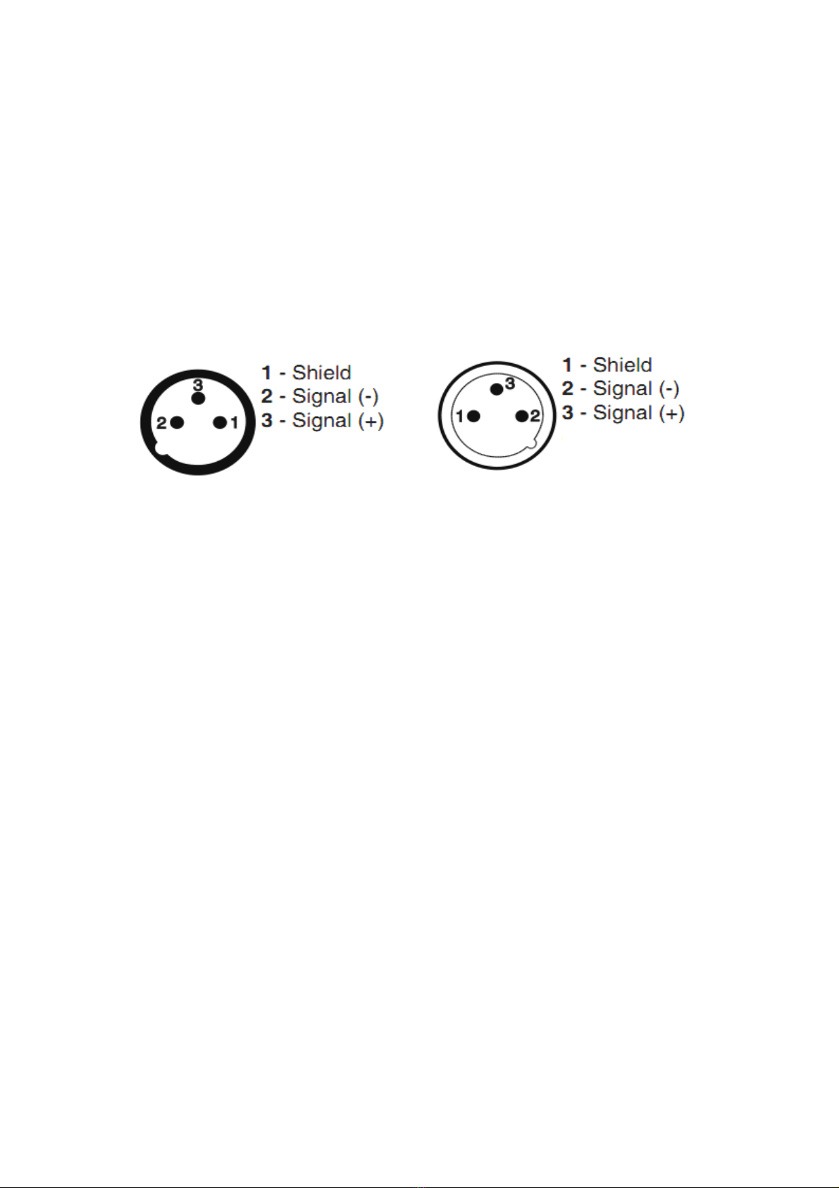
The fixture is equipped with both 3-pin and 5-pin XLR sockets for DMX input and output.The
sockets are wired in parallel. Only use a shielded twisted-pair cable designed for RS-485 and 3-pin
or 5-pin XLR-plugs and connectors in order to connect the controller with the fixture or one fixture
with another.
Occupation of the XLR-connection:
DMX - output DMX-input
XLR mounting-sockets (rear view): XLR mounting-plugs (rear view):
If you are using the standard DMX controllers, you can connect the DMX output of the controller
directly with the DMX input of the first fixture in the DMX chain. If you wish want to connect DMX
controllers with other XLR outputs, you need to use a dapter-cables.
Building a serial DMX chain:
Connect the DMX output of the first fixture in the DMX chain with the DMX input of the next fixture.
Always connect one output with the input of the next fixture until all fixtures are connected.
Caution: At the last fixture, the DMX cable has to be terminated with a terminator. Solder a
120 Ωresistor between Signal (–) and Signal (+) into a XLR plug and plug it in the DMX output of
the last fixture.
IMPORTANT: The wires must not make contact with each other or with the metal casing of the
connectors. The casing itself must be connected to the shield braid and to pin 1 of the connectors.
Switching on the projector
Press the switch. The projector starts resetting the effects. At the same time, the following
information scrolls on the display:
On conclusion of resetting in case of absence of the DMX signal, Pan and Tilt move to the “Home”
position (Pan 50% - Tilt 50%). The control panel has a display and buttons for the complete
programming and management of the projector menu. The display can be in one of two conditions:
rest status and setting status. When it is in the rest status, the display shows the projector’s DMX
address and the Fixture ID address (if set).
During menu setting status, after a wait time (about 30 seconds) without any key having been
pressed, the display automatically returns to rest status.
It should be noted than when this condition occurs, any possible value that has been modified
but not yet confirmed with the F key will be cancelled.
Setting the projector starting address
On each projector, the starting address must be set for the control signal (addresses from 1 to
512).

7
The address can also be set with the projector switched off.
Setting the address:
5. Functions of the buttons - Using the
menu
"RNS"—Encoder wheel moves between menu items on the same level, scrolls between
values .
"ESC"—Button-leaves menu without saving changes
"ENTER"—button enters menu, comfirms adjusted values and leaves menu.
Setting addresses and options with the projector disconnected
The projector’s DMX address, as well as other possible operating options, can also be set
when the appliance is disconnected from the electricity supply.
All that is needed is to press " ENTER " to momentarily activate the display and thus access
the settings. Once the required operations have been carried out, the display will switch off again
after a wait time of 30 seconds.

8
6. MENU SETTING v1.0
Fixture Address DMX Address 001----512
Personality
Display Adjusting
Display Permanent On
(ON/Off)
Display Intensity (1..10)
Display Backlight (1..5..10)
Display turned (On/Off)
DMX Presetting
Mode 1
Ch.1
Ch.24
Set Active
Mode 2
Ch.1
Ch.20
Set Active
Mode 3
Ch.1
Ch.16
Set Active
Pan/Tilt Presetting
Pan Reverse(On,Off)
Tilt Reverse(On,Off)
Pan/Tilt Feedback
(On,Off)
Pan/Tilt mode Time Mode
Speed Mode
Pan/Tilt Speed Standard Speed
High Speed
Colour Calibration On/off
Active Blackout While Blackout D.M.C. (On,Off)
pan/Tilt Moving (On,Off)
Temperature Unit ℃, ℉
Iinit Effect Positions Ch.1
Ch.32
Default Setting
Fixture
information
Power On Time
Total Hours
Resetable Hours
Fixrure Temperatures
Current Temp. Ambient Temp.[℃]
LEDs Temp.[℃]
Maximum Temp. Ambient Temp.[℃]
LEDs Temp.[℃]
Software Version
Product IDs MAC Adr.
Code

9
DMX Values CH1
Ch32
Test sequences Mode 1
Pan (0-255)
Tilt
Zoom
Focus
Run Test Program
Mode 2 Run Test Program
Manual Mode Manual Effect Control Pan (0-255)
Dimmer fine(0-255)
Stand-alone
setting
Editing Program
Program1
Program2
Program3
Edit Steps
Step1~Step99
Pan (0-255)
Dimmer fine (0-255)
Step Time
(0.1-25.5s)
Save
Save and copy
Start Step (1-99)
End Step (1-99)
Playing Program
Test Program In Loop
Program 1In Loop
Program 2In Loop
Program 3In Loop
Presetting Playback
Disabled
Test Program
Program1
Program2
Program3
Reset functions
Reset All
Pan/Tilt
Zoom
Special
functions Effect Adjustment
DMX Values Pan (0-255)
Dimmer (0-255)
Calibrate Values
Red(0-255)
Green (0-255)
Save and Reset
Restore

10
7. DMX protocol v1.0
Model Channel Value Founction
1 2 3
1 1 1
Shutter/Strobe
0-31 Shutter closed
32-63 Strobe effect from slow--> fast
64-95 Strobe effect from slow--> fast (All zones together)
96-111 Zone effects+rainbow effects speed control, slow--> fast
112-127 Zone effects+rainbow effects speed control, fast--> slow
128-143 Opening pulses in sequences from slow--> fast
144-159 Closing pulses in sequences from fast--> slow
160-175 Random strobe effect from slow--> fast
176-191 Random strobe effect from slow--> fast
192-223 Random strobe effect from slow --> fast (All zones together)
224-255 Shutter open
2 2 2 0-255
Dimmer (8 bit)
Dimmer intensity from 0% to 100%
3 3 3 0-255
Zoom
Zoom from max to min. beam angle
4 4 4 0-255
Pan(8 bit)
Pan movement by 540°
5 5 5 0-255
Pan fine(16 bit)
Fine control of pan movement
6 6 6 0-255
Tilt(8bit)
Tilt movement by 270°
7 7 7 0-255
Tilt fine(16bit)
Fine control of tilt movement
8 8 8
Special functions
0-49 Reserved
To activate following functions , stop in DMX value
for at least 3sec. and shutter must be closed at least
3sec. (Shutter channel 35/19/14/9/9 must be at
range of 0-31DMX). Corresponding menu items are
temporily overrided.
50-59 Pan/Tilt speed mode
60-69 Pan/Tilt time mode
70-79 Blackout while pan/tilt moving
80-89 Disabled blackout while pan/tilt moving

11
90-99 Theatre mode On
100-109 Theatre mode Off
110-139
Reserved
To activate following reset function, stop in DMX
value for at least 3 sec.
140-149 Pan/Tilt reset
150-179 Reserved
180-189 Zoom reset
190-199 Reserved
200-209 Total reset
210-255 Reserved
9 9 9
Beam RGBW Virtual Colour Wheel
For detailed description see " Virtual colour wheel- colour mixing
chart
0 No function
1~2 White 2700 K
3 White 2700 K (Halogen lamp mode*)
4~5 White 3200 K
6 White 3200 K (Halogen lamp mode*)
7~9 White 4200 K
10~12 White 5600 K
13-15 White 8000 K
16 Blue (Blue=full, Red+Green+White=0)
17-55 Red=0, Green->up,Blue =full, White=0
56 Light Blue (Red=0, Green=full, Blue =full, White=0)
57-95 Red=0, Green=full, Blue->down, White=0
96 Green (Red=0, Green=full, Blue =0, White=0)
97-134 Red->up, Green=full, Blue=0, White=0
135 Yellow (Red=full, Green=full, Blue=0, White=0)
136-174 Red=full, Green->down, Blue=0, White=0
175 Red(Red=full, Green=0, Blue=0, White=0)
176-214 Red=full, Green=0, Blue->up, White=0
215 Magenta (Red=full, Green=0, Blue=full, White=0)
216-246 Red -> down, Green=0, Blue=full, White=0
247 Blue (Red=0, Green=0, Blue=full, White=0)
248-255 Reserved
_ 10 10
Beam Red /Red fine - all zones
0-255 Red LEDs saturation control (0-100%)
0-255 Fine red LEDs saturation control
_ 11 11
Beam Green /Green fine -all zones
0-255 Green LEDs saturation control (0-100%)
0-255 Fine green LEDs saturation control
_ 12 12 Beam Blue /Blue fine - all zones

12
0-255 Blue LEDs saturation control (0-100%)
0-255 Fine blue LEDs saturation control
_ 13 13
Beam White /White fine - all zones
0-255 White LEDs saturation control (0-100%)
0-255 Fine white LEDs saturation control
10 _
Beam Red /Red fine - zone 1
0-255 Red LEDs saturation control (0-100%)
0-255 Fine red LEDs saturation control
11 _
Beam Green /Green fine -zone 1
0-255 Green LEDs saturation control (0-100%)
0-255 Fine green LEDs saturation control
12 _
Beam Blue /Blue fine - zone 1
0-255 Blue LEDs saturation control (0-100%)
0-255 Fine blue LEDs saturation control
13 _
Beam White /White fine - zone 1
0-255 White LEDs saturation control (0-100%)
0-255 Fine white LEDs saturation control
14 _
Beam Red /Red fine - zone 2
0-255 Red LEDs saturation control (0-100%)
0-255 Fine red LEDs saturation control
15 _
Beam Green /Green fine -zone 2
0-255 Green LEDs saturation control (0-100%)
0-255 Fine green LEDs saturation control
16 _
Beam Blue /Blue fine - zone 2
0-255 Blue LEDs saturation control (0-100%)
0-255 Fine blue LEDs saturation control
17 _
Beam White /White fine - zone 2
0-255 White LEDs saturation control (0-100%)
0-255 Fine white LEDs saturation control
18 14 14
CTO
0 No function
1-255 Colour temperature correction from 20000K to 2700K
(menu item "Colour Calibration Mode"=Off)
1-255 Colour temperature correction from 15500K to 2700K
(menu item "Colour Calibration Mode"=On)
19 15 15
Beam Brightness
0~31 Beam RGBW NORM
32~127 Beam RGBW Fine
128~223 Beam RGBW OFF
224~255 Beam RGBW NORM
20 17 _
Aura RGB Virtual Colour Wheel
0 No function
1~3 White 2700 K

13
4~6 White 3200 K
7~9 White 4200 K
10~12 White 5600 K
13-15 White 8000 K
16 Blue (Blue=full, Red+Green)
17-55 Red=0, Green->up,Blue =full
56 Light Blue (Red=0, Green=full, Blue =full)
57-95 Red=0, Green=full, Blue->down
96 Green (Red=0, Green=full, Blue =0)
97-134 Red->up, Green=full, Blue=0
135 Yellow (Red=full, Green=full, Blue=0)
136-174 Red=full, Green->down, Blue=0
175 Red(Red=full, Green=0, Blue=0)
176-214 Red=full, Green=0, Blue->up
215 Magenta (Red=full, Green=0, Blue=full)
216-246 Red -> down, Green=0, Blue=full
247 Blue (Red=0, Green=0, Blue=full)
248-255 Reserved
21 18 _ Aura Red
0-255 Red LEDs saturation control (0-100%)
22 19 _ Aura Green
0-255 Green LEDs saturation control (0-100%)
23 20 _ Aura Blue
0-255 Blue LEDs saturation control (0-100%)
24 16 16
Pan/Tilt speed, Pan/Tilt time
0 Max. speed (tracking mode)
1-255 P./T. speed-set Speed Mode in menu: P./T. Mode
Speed from max. to min. (vector mode)
1-255 P./T. time - set Time Mode in menu: Pan/Tilt Mode
Time from 0. 1s to 13 s.

14
8. TECHNICAL INFORMATION
AC power: 100-240 V nominal, 50/60 Hz
Maximum total power consumption: 1020 W
Light source: Osram high-power LED emitters
Beam color mixing: RGBW
Aura color mixing: RGB
Total output: 11000 lumens (zoom at maximum)
Minimum LED lifetime: 60 000 hours (to >70% luminous output)
Control: DMX, protocol modes 24/20/16
3-editable programs, each up to 100 steps
RDM: Implemented
Pan/Tilt used 3-Phase 1.2° ENCAPSULATED STEPPING MOTOR, ZOOM linear
actuators.
Pan and tilt speed: Adjustable via onboard control panel and DMX
Pan/Tilt movement: Pan: 540°; Tilt: 270°
Control resolution: 8-bit, with 16-bit control of pan & tilt
Resolution: PAN=2.11°, PAN FINE=0.008°, TILT=0.98°, TILT FINE=0.004°
Virtual color wheel:237 colors including whites (2700K, 3200K, 4200K, 5600K and
8000K)
Color temperature control: CTO, variable 10 000 - 2500 K
Strobe effect with variable speed (max. 20 flashes per second)
Zoom: 11° - 60°
Display: Blue/white LCD graphic
Color: Black
Housing: High-impact flame-retardant thermoplastic
Protection rating: IP20
Weight: 9.33kg

15
9. Maintenance and cleaning
It is absolutely essential that the fixture is kept clean and that dust, dirt and
smoke-fluid residues must not build up on or within the fixture. Otherwise, the fixture‘s light-output
will be significantly reduced. Regular cleaning will not only ensure the maximum light-output, but will
also allow the fixture to function reliably throughout its life.
A soft lint-free cloth moistened with any good glass cleaning fluid is recommended, under no
circumstances should alcohol or solvents be used!
The head of transparent cover will require weekly cleaning as smoke-fluid tends to building up
residues, reducing the light-output very quickly. The cooling fans should be cleaned monthly.
The interior of the base should be cleaned at least annually using a vacuum-cleaner or an air-jet.
More complicated maintenance and service operations are only to be carried out by authorized
distributors.
9.1 Replacing fuse
Only replace the fuse by a fuse of the same type and rating.
Before replacing the fuse, unplug mains lead!
If you need to replace the main fuse, follow the instructions:
1) Remove the rear cover of the base by unscrewing 6 fastening screws.
2) Remove the old fuse from the fuse holder.
3) Install the new fuse into the fuse holder.
4) Replace the rear cover back to the base..
CAUTION!
Disconnect from the mains before starting any maintenance work
Table of contents