Max PJR265(CE) Product information sheet

PJR265(CE)
CORDLESS BRUSHLESS ROTARY HAMMER
ORIGINAL USER MANUAL
Original instructions
ENGLISH
BEFORE USING THIS TOOL, STUDY THIS MANUAL TO ENSURE SAFETY WARNING
AND INSTRUCTIONS.
KEEP THESE INSTRUCTIONS WITH THE TOOL FOR FUTURE REFERENCE.
WARNING
PJR265_CE.book 1 ページ 2010年10月13日 水曜日 午後4時51分

2
14
5
11
12
25
10
9
8
7
6
3
2
Fig.B
13
14
16
17
15
Fig.C
24
23
22
21
20
19
18
Fig.D
13
Fig.E
16
1
2
Fig.F
PJR265_CE.book 2 ページ 2010年10月13日 水曜日 午後4時51分

3
20
Fig.G
7
Fig.H
20
Fig.I
20
Fig.J
Fig.K Fig.L
13
Fig.M
16
Fig.N
PJR265_CE.book 3 ページ 2010年10月13日 水曜日 午後4時51分

4
12
Fig.O
11
Fig.P
Fig.Q
3
1
Fig.R
1
Fig.S
2
Fig.T
2
Fig.U Fig.V
PJR265_CE.book 4 ページ 2010年10月13日 水曜日 午後4時51分

5
5
4
Fig.W
810
Fig.X
6
12
Fig.Y
Fig.Z
Fig.AA
Fig.AB
PJR265_CE.book 5 ページ 2010年10月13日 水曜日 午後4時51分

6
DEFINITIONS OF SIGNAL WORDS
WARNING: Indicates a potentially hazardous situation which, if not avoided, could result in death or
serious injury.
CAUTION: Indicates a potentially hazardous situation which, if not avoided, may result in minor or
moderate injury.
NOTE: Emphasizes essential information.
INDEX
1. GENERAL POWER TOOL SAFETY WARNINGS.............6
2. HAMMER SAFETY WARNINGS........................................9
3. SPECIFICATIONS AND TECHNICAL DATA .................. 11
4. BATTERY INSTRUCTIONS ............................................. 13
5. OPERATING INSTRUCTIONS......................................... 16
6. MAINTENANCE................................................................20
7. STORAGE ........................................................................20
1. GENERAL POWER TOOL
SAFETY WARNINGS
1. WORK AREA SAFETY
•Keep work area clean and well lit. Clut-
tered or dark areas invite accidents.
•Do not operate power tools in explo-
sive atmospheres, such as in the pres-
ence of flammable liquids, gases or
dust. Power tools create sparks which
may ignite the dust or fumes.
•Keep children and bystanders away
while operating a power tool. Distrac-
tions can cause you to lose control.
2. ELECRRICAL SAFETY
•Power tool plugs must match the out-
let. Never modify the plug in any way.
Do not use any adapter plugs with
earthed (grounded) power tools. Un-
modified plugs and matching outlets will
reduce risk of electric shock.
•Avoid body contact with earthed or
grounded surfaces, such as pipes, ra-
diators, ranges and refrigerators.
There is an increased risk of electric
shock if your body is earthed or grounded.
•Do not expose power tools to rain or
wet conditions. Water entering a power
tool will increase the risk of electric shock.
•Do not abuse the cord. Never use the
cord for carrying, pulling or unplug-
ging the power tool. Keep cord away
from heat, oil, sharp edges and moving
READ ALL SAFETY WARNINGS AND ALL
INSTRUCTIONS.
Failure to follow the warnings and instructions
may result in electric shock, fire and/or seri-
ous injury. Save all warnings and instruc-
tions for future reference. The term "power
tool" in the warnings refers to your mains-op-
erated (corded) power tool or battery-operat-
ed (cordless) power tool.
WARNING
PJR265_CE.book 6 ページ 2010年10月13日 水曜日 午後4時51分

7
parts. Damaged or entangled cords in-
crease the risk of electric shock.
•
When operating a power tool outdoors,
use an extension cord suitable for out-
door use.
Use of a cord suitable for out-
door use reduces the risk of electric shock.
•Do not use the power tool in the rain,
where water is splashing, in a wet
place, or in a damp place. Using the tool
in these or similar conditions will increase
the risk of electric shock, dangerous mal-
function, and overheating. If operating a
power tool in a damp location is una-
voidable, use a residual current device
(RCD) protected supply. Use of an RCD
reduces the risk of electric shock.
3. PERSONAL SAFETY
•
Stay alert, watch what you are doing and
use common sense when operating a
power tool. Do not use a power tool while
you are tired or under the influence of
drugs, alcohol or medication.
A moment
of inattention while operating power tools
may result in serious personal injury.
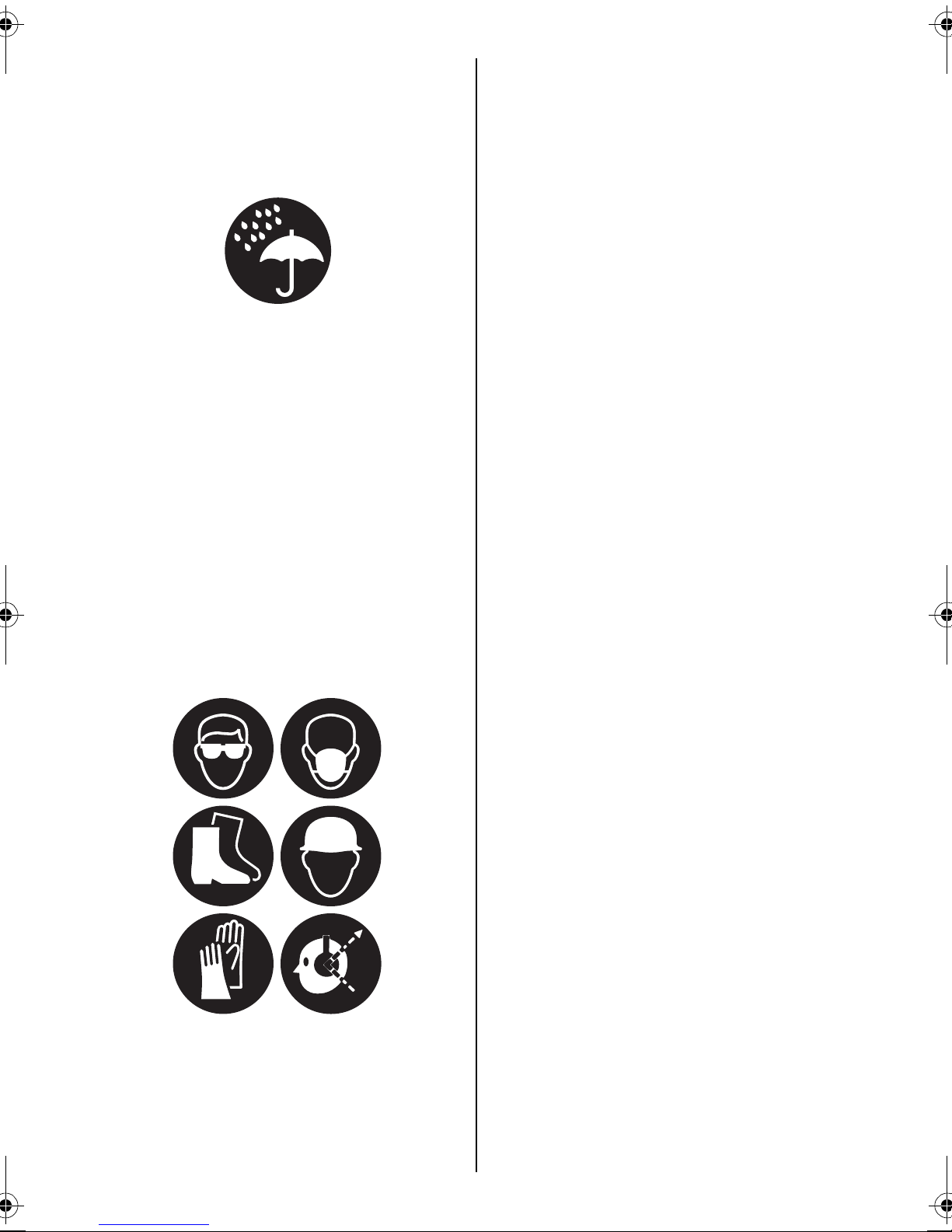
•Use personal protective equipment.
Always wear eye protection. Protective
equipment such as dust mask, non-skid
safety shoes, hard hat, or hearing protec-
tion, hand protector used for appropriate
conditions will reduce personal injuries.
•Prevent unintentional starting. Ensure
the switch is in the off-position before
connecting to power source and/or
battery pack, picking up or carrying
the tool. Carrying power tools with your
finger on the switch or energizing power
tools that have the switch on invites acci-
dents.
•Remove any adjusting key or wrench
before turning the power tool on.
A wrench or a key left attached to a rotat-
ing part of the power tool may result in a
personal injury.
•Do not overreach. Keep proper footing
and balance at all times. This enables
better control of the power tool in unex-
pected situations.
•Dress properly. Do not wear loose
clothing or jewellery. Keep your hair,
clothing and gloves away from moving
parts. Loose clothes, jewellery or long hair
can be caught in moving parts.
•If devices are provided for the connec-
tion of dust extraction and collection
facilities, ensure these are connected
and properly used. Use of dust collec-
tion can reduce dust-related hazards.
4. POWER TOOL USE AND CARE
•Do not force the power tool. Use the
correct power tool for your applica-
tion. The correct power tool will do the job
better and safer at the rate for which it
was designed.
•Do not use the power tool if the switch
does not turn it on and off. Any power
tool that cannot be controlled with the
switch is dangerous and must be re-
paired.
•Disconnect the plug from the power
source and/or the battery pack from
the power tool before making any ad-
justments, changing accessories, or
storing power tools. Such preventive
safety measures reduce the risk of start-
ing the power tool accidentally.
•Store idle power tools out of the reach
of children and do not allow persons
unfamiliar with the power tool or these
instructions to operate the power tool.
Power tools are dangerous in the hands
of untrained users.
•Maintain power tools. Check for mis-
alignment or binding of moving parts,
breakage of parts and any other condi-
tion that may affect the power tool's
operation. If damaged, have the power
PJR265_CE.book 7 ページ 2010年10月13日 水曜日 午後4時51分

8
tool repaired before use. Many acci-
dents are caused by poorly maintained
power tools.
•Keep cutting tools sharp and clean.
Properly maintained cutting tools with
sharp cutting edges are less likely to bind
and are easier to control.
•Use the power tool, accessories and
tool bits etc. in accordance with these
instructions, taking into account the
working conditions and the work to be
performed. Use of the power tool for op-
erations different from those intended
could result in a hazardous situation.
5. BATTERY TOOL USE AND CARE
•DO NOT DISPOSE OF BATTERY
PACKS/BATTERIES INTO FIRE OR
WATER. Battery packs/batteries should
be collected, recycled or disposed of in an
environmental-friendly manner.
•PROTECT THE BATTERY AGAINST
HEAT, ALSO AGAINST CONTINUOUS
SUN IRRADIATION AND FIRE. There is
danger of explosion.
•CHARGE THE BATTERY PACK IN A
TEMPERATURE RANGE 5°(41F) TO
40°(104F)
•DO NOT DISPOSE OF POWER TOOLS
INTO HOUSEHOLD WASTE. According
to the European Guideline 2002/96/EC
for Waste Electrical and Electronic Equip-
ment and its implementation into national
right, power tools that are no longer usa-
ble must be collected separately and dis-
posed of in an environmentally correct
manner.
•DEFFECTIVE OR DEAD OUT BATTERY
PACKS/BATTERIES MUST BE RECY-
CLED ACCORDING TO THE GUIDE-
LINE 91/157/EEC.
•Recharge only with the charger speci-
fied by the manufacturer. A charger that
is suitable for one type of battery pack
may create a risk of fire when used with
another type of battery pack.
•Use power tools only with specifically
designated battery packs. Use of any
other battery packs may create a risk of
injury and fire.
•When battery pack is not in use, keep
it away from other metal objects, like
paper clips, coins, keys, nails, screws
or other small metal objects, that can
make a connection from one terminal
to another. Shorting the battery terminals
together may cause burns or a fire.
•Under abusive conditions, liquid may
be ejected from the battery; avoid con-
tact. If contact accidentally occurs,
flush with water. If liquid contacts
eyes, additionally seek medical help.
Liquid ejected from the battery may cause
irritation or burns.
6. SERVICE
•
Have your power tool serviced by a qual-
ified repair person using only identical
replacement parts.
This will ensure that
the safety of the power tool is maintained.
PJR265_CE.book 8 ページ 2010年10月13日 水曜日 午後4時51分

9
2. HAMMER SAFETY WARN-
INGS
1. BE SURE TO KEEP HANDS AWAY FROM
THE TRIGGER SWITCH AND DETACH
THE BATTERY PACK WHEN REPLACING
OR ADJUSTING THE BIT, WHEN AB-
NORMALITIES OCCUR, AND WHEN THE
EQUIPMENT IS NOT BEING USED
Leaving the Battery pack installed in these
situations may cause breakdowns or dam-
age.
2. HOLD TOOL BY INSULATED GRIPS
WHEN PERFORMING AN OPERATION,
BECAUSE THE TOOL'S BIT MAY CON-
TACT HIDDEN "LIVE" WIRE
Contacting with a "live" wire may make ex-
posed metal parts of the tool "electrified" and
shock the operator. Failure to do so may re-
sult in serious injury.
3. MAKE SURE THE BIT IS SECURED IN
PLACE BEFORE OPERATION
Failure to do so may result in serious injury.
4. DO NOT POINT THE TOOL AT ANYONE
Personal injury may result if the tool catches
an operator or anyone working near him.
While working with the tool, be extremely
careful not to bring hands, legs, and other
body parts near the bit of the tool.
5. NEVER MODIFY THE TOOL
Modifying the tool will impair performance
and operating safety. Any modification may
lead to serious injury and void the tool war-
ranty.
6. MAINTAIN THE TOOL IN GOOD OPER-
ATING CONDITION
(CHECK TIGHTNESS OF SCREWS BE-
FORE OPERATION)
To secure operating safety and ensure top
performance, keep the tool free of wear and
damage.
Under normal operation, the tool is de-
signed to produce vibration. Due to the vi-
bration, the screws can come loose, caus-
ing damage to the tool or serious injury.
Also keep the tool's hand grip dry and clean,
especially free of oil and grease.
7. LET THE TOOL WARM UP FOR SEV-
ERAL MINUTES BEFORE USE
In cold weather or when the tool has not
been used for a long period of time, the in-
ternal lubrication in the tool might not be in-
sufficient. In such cases, let the tool warm up
for several minutes by operating it with no
load. Lacking sufficient internal lubrication,
the tool might not operate at full perform-
ance.
8. MAKE SURE TO OPERATE THE TOOL ON
A FIRM FOOTING
Failure to do so may lead to serious injury.
9. MAKE SURE THERE IS NO ONE BELOW
WHEN USING THE TOOL IN HIGH LO-
CATIONS
Failure to do so may lead to serious injury of
the person below.
10. HOLD THE TOOL FIRMLY WITH BOTH
HANDS
Failure to do so may lead to serious injury.
11. KEEP HANDS AWAY FROM MOVING
PARTS
12. DO NOT LEAVE THE TOOL RUNNING
Operate the tool only when hand-held.
13. DO NOT TOUCH THE BIT OR PARTS
CLOSE TO THE BIT IMMEDIATELY AF-
TER OPERATION
These parts may be extremely hot. Touching
these parts may cause serious injury.
14. USE ONLY THE AUTHORIZED BATTERY
PACK
Use only MAX JPL925 battery pack. If the
tool is connected to a power supply other
than the authorized pack, such as a re-
chargeable battery, a dry cell, or a storage
battery for use in automobiles, the tool may
be damaged, break down, overheat, or even
catch on fire. Do not connect this tool to any
power supply except the MAX JPL925 bat-
tery pack.
15. TO ENSURE MAXIMUM PERFORMANCE,
FULLY CHARGE THE BATTERY BEFORE
USE
A new battery pack or one not used for ex-
tended periods may have self-discharged
and thus may need recharging to restore it to
a fully charged condition. Before operating
the tool, make sure to charge the Battery
pack with the designated MAX Battery
charger JC928.
PJR265_CE.book 9 ページ 2010年10月13日 水曜日 午後4時51分

10
16. BATTERY CHARGING PRECAUTION
1 Use only MAX Battery charger JC928
and Battery Pack JPL925
Failure to do so may cause the Battery to
overheat or catch fire leading to serious
injury.
2 Charge the Battery from AC between
100V and 240V wall sockets
Failure to do so may result in overheating,
or inadequate charging possibly causing
serious injury.
3 Never use a transformer
4 Never connect the Battery charger to
an engine generator direct-current
power supply
The charger will break down or be dam-
aged from burning.
5 Avoid charging the Battery pack in the
rain, in a damp place, or where water is
splashing
Charging a damp or wet Battery pack will
cause an electric shock or a short circuit
that may lead to damage from burning
and even the tool catching on fire.
6 Do not touch the power cord or plug
with a wet hand or glove
This may cause injury from electric shock.
7 Do not put a cloth or any other cover
on the Battery charger while the Bat-
tery pack is being charged
This will cause overheating and damage
from burning, or the Charger may even
catch fire.
8 Keep the Battery pack and Battery
charger away from heat and flames
9 Do not charge the Battery pack near
flammable materials
10 Charge the Battery pack in a well ven-
tilated place
Avoid charging the Battery pack where it
will be in direct sunlight.
11 Charge the Battery pack in a tem-pera-
ture range of 5°C (41°F) to 40°C (104°F)
12 Avoid continual use of the Battery
charger
Rest the Charger for 15 minutes between
charges to avoid functional trouble with
the unit.
13 Any objects that block the ventilation
holes or Battery pack receptacle may
cause electric shock or functional
troubles
Operate the charger free of dust or other
foreign materials.
14 Handle the power cord carefully
Do not carry the Battery charger by its
power cord. Do not use the power cord to
disconnect it from a wall socket; this will
damage the cord and break the wires or
cause a short circuit. Do not let the power
cord contact sharp edged tools, hot ma-
terials, oil, or grease. A damaged cord
must be repaired or replaced.
15 Do not charge non rechargeable bat-
teries with this charger.
16 This charger is not intended for use by
children or disabled persons without
supervisor.
17 Children should be supervised to en-
sure that they do not play with the
charger.
18 Put a pack cap on the terminal of the
Battery pack
When the Battery pack is not in use, put a
pack cap on its terminal to prevent short
circuits.
Keep it away from other metal objects,
such as clips, coins, keys, nails, screws or
other small metal objects, that can make a
connection from one terminal to another.
19 Do not leave or store the tool in a vehi-
cle or in direct sunlight during sum-
mer. Leaving the tool in high
temperature conditions may cause the
battery pack to deteriorate.
20 Do not store a fully discharged battery
pack. If a fully discharged battery pack
is removed from the system and left for
a long period of time, it may be-come
damaged. Recharge the battery imme-
diately when it has been discharged.
PJR265_CE.book 10 ページ 2010年10月13日 水曜日 午後4時51分

11
3. SPECIFICATIONS AND TECHNICAL DATA
1. NAME OF PARTS (See Fig. B, C and D)
Fig. B
1 DEPTH GAUGE
2 SDS PLUS TOOL HOLDER
3 SIDE HANDLE
4 CHANGEOVER LEVER
5 LOCK BUTTON
6LEDLAMP
7 BATTERY PACK JPL925
8 CHANGEOVER SWITCH
9 CONTROL PANEL
10 STATUS INDICATOR LED
(RED / GREEN)
11 ROTATIONAL DIRECTION SWITCH
12 TRIGGER SWITCH (CONTINUOUSLY
VARIABLE)
25 SPECIFICATION LABEL
Fig. C
13 PACK CAP
14 TERMINAL
15 VENTILATION WINDOW
16 LATCH
17 SPECIFICATION LABEL
Fig. D
18 BATTERY PACK ENTRY POINT
19
LED LAMP (ORANGE)
CHARGING STATUS
INDICATOR LAMP
20
LED LAMP (RED / GREEN)
CHARGING STATUS
INDICATOR LAMP
21 SPECIFICATION LABEL
22 VENTILATION WINDOW
23 POWER CORD
24 CE (VDE) POWER PLUG
2. TOOL SPECIFICATIONS
<Battery charger>
PRODUCT NO. PJR265
WEIGHT 3.7kg(8.1lbs.)(Battery included)
HEIGHT 210mm (8-1/4")
WIDTH 82mm (3-1/4")
LENGTH 332mm (13-1/16")
TOOL HOLDER SDS PLUS
VOLTAGE / BAT-
TERY
25.2V,
Li-ion Battery pack JPL925
RATED SPEED Normal mode : 0~920 min-1
Slow mode : 0~560 min-1
IMPACT
FREQUENCY AT
RATED SPEED
Normal mode : 0~4,700 min-1
Slow mode : 0~2,860 min-1
MAXIMUM DRILL-
ING DIAMATER
Concrete : 26mm (1")
Steel : 13mm (1/2")
Wood : 30mm (1-3/16")
MOTOR Brushless DC Motor
OPERATING TEM-
PERATURE
-5°C to 40°C (14°F to 104°F)
OPERATING HU-
MIDITY
80% RH or less
PRODUCT NAME MAX lithium ion battery charger
PRODUCT NO. JC928(CE)
INPUT AC100-240V 50/60Hz 1.62-
0.68A
OUTPUT DC 7.2/10.8/14.4V 7A
DC 18/21.6/25.2/28.8V 3.9A
WEIGHT 1.6kg (3.5lbs.)
OPERATING
TEMPERATURE
5°C to 40°C (41°F to 104°F)
OPERATING
HUMIDITY
80% RH or less
PJR265_CE.book 11 ページ 2010年10月13日 水曜日 午後4時51分

12
<Battery pack>
BATTERY CHARGER:
Use only an authorized Battery charger, MAX JC928.
3. TECHNICAL DATA
1NOISE
The typical A-weighted noise level deter-
mined according to EN60745-2-6:
•Sound pressure level (LpA): 108dB (A)
•Sound power level (LWA): 97dB (A)
•Uncertainty (K): 3dB (A)
2VIBRATION
The vibration total value (tri-axial vector
sum) determined according to EN60745-2-1:
•Work mode: Drilling into metal
•Vibration emission: (ah, HD): ≤2.5m/s2
•Uncertainty (K): 1.5m/s2
The vibration total value (tri-axial vector
sum) determined according to EN60745-2-6:
•Work mode: hammer-drilling into con-
crete, 16mm diameter and 100mm depth
•Vibration emission: (ah, HD): 18.2m/s2
•Uncertainty (K): 1.5m/s2
3RADIATED EMISSION 30-1000 MHZ
Class B
4Overvoltage category
5Pollution degree
Pollution degree : degree 4 according to IEC
60664-1 (Both of PJR265 and JC928(CE)).
4. APPLICATIONS
Hammer-drilling in the following materials
•Concrete
•Brick
•Stone
Drilling in the following materials
•Wood
•Metal
5. ABOUT PRODUCTION YEAR
This product bears production number in the
body. The two digits of the number from left
indicates the production year.
PRODUCT NAME MAX lithium ion battery pack
PRODUCT NO. JPL925
BATTERY TYPE Lithium ion battery
NOMINAL VOLTAGE DC25.2 V
NOMINAL CAPACITY 3.0 Ah (3,000 mAh)
CHARGING TIME
(USE WITH JC928(CE))
Quick charging - Approximately 35 minutes (Apprx. 90% of capacity)
Full charging - Approximately 45 minutes at 25°C(77°F) (100% of capacity)
ACCESSORIES Pack cap (For preventing short circuit)
WEIGHT 0.9 kg (2.4lbs.)
CHARGING TEMPERATURE 5°C to 40°C (41°F to 104°F)
OPERATING TEMPERATURE -5°C to 40°C (14°F to 104°F)
OPERATING HUMIDITY 80% RH or less
Wear ear protection
PRODUCT Overvoltage category
PJR265 CORD-LESS
BRUSH-LESS ROTA-
RY HAMMER
Category 1
according to
IEC 60664-1
JC928(CE)
BATTERY CHARGER
Category 2
according to
IEC 60664-1
(Example)
0 8 8 2 6 0 3 5 D
Year 2008
PJR265_CE.book 12 ページ 2010年10月13日 水曜日 午後4時51分

13
4. BATTERY INSTRUCTIONS
1. Charging
•Before removing the Battery pack from the
tool, set the Rotational direction
switch(Fig. B.11) at middle position, and
keep hands away from the Trigger
switch(Fig. B.12).
1(Fig. E) A Pack cap(Fig. E 13) that is used
to prevent short circuits must be re-
moved from the terminal of the Battery
pack.
(Fig. F) When charging the Battery pack, re-
move it from the tool by pushing on its latches
(Fig. F 16) from both sides while firmly holding
the grip of the tool.
2(Fig. G) Plug the charger into a wall sock-
et (100V - 240V).
The red light, a current-carrying indica-
tor, (Fig. G 20) will flash on and off with
two short (Pipi) beep sounds.
WHEN THE ORANGE STANDBY
LIGHT IS LIT
When the Battery pack is hot (after continuous
use or exposure to direct sunlight) the Charger
will automatically switch to standby to protect the
Battery. The orange standby light will be lit until
the Battery's temperature lowers to a safe level,
The Battery will then be charged auto-matically.
WHEN THE BATTERY PACK IS AT
LOW TEM-PERATURE
When the Battery pack is at low temperature, its
charging is automatically suspended until its
temperature increases (higher than 5°C (41°F)),
in order to protect it, even if it is set in the Charg-
er.
Leave the Battery pack at normal temperature in
the room for some time, and then, charge it
again.
WHEN THE ORANGE STANDBY
LIGHT BLINKS
This indicates the Battery cannot be charged.
Unplug the Charger and check the charging re-
ceptacle. If there are any foreign objects, remove
them with a soft dry cloth. If the orange light still
blinks or there are no foreign objects, there may
be a problem with the battery or charger. Return
to dealer for service.
3(Fig. H) Charge the Battery pack.
(1) Fully insert the Battery into the receptacle on
the Charger until it sits securely on the end.
(2) Charging will start automatically and will be
indicated by the red charging light with
beeps.
(3) Charging time is approximately 35 minutes
(90% capacity). This will vary by tempera-
ture and source voltage.
(4) For batteries those are at low temperatures
(10°C (50°F) or lower), charging time must
be extended longer. When charging at low
temperatures, both of the red and the or-
ange charging light will be lit.
4(Fig. I) When the battery pack has been
recharged, the "red" lamp turns off and
the "green" lamp blinks.
The "green" LED lamp(Fig. I 20) blinks
slowly and a long beep sounds for ap-
proximately 2 seconds. Now, the battery
has been recharged to approximately
90% of its capacity. Quick charging takes
approxi-mately 35 minutes (however, the
recharging time and capacity slightly
change depending on the ambient tem-
perature and power voltage).
(Fig. J) You can use the battery pack when
quick charging is complete. However, if you
leave the battery pack on the charger, re-
charging will continue. When the battery is
fully recharged (to 100% capacity), the
"green" LED lamp lights up (and a long beep
sounds for approximately 2 seconds).
(1) (Fig. K) After you have recharged the battery
pack, remove it from the charger.
(2) (Fig. L) Unplug the charger power cord from
the wall socket.
WARNING
PJR265_CE.book 13 ページ 2010年10月13日 水曜日 午後4時51分

14
•When the battery pack is fully discharged,
do not leave it for a long time without re-
charging. If the fully discharged battery
pack is removed from the system and left
for a long time, the battery pack may be-
come damaged. Recharge the battery im-
mediately when it has been discharged.
•Do not leave the battery pack on the charg-
er. If the above is not observed, a weak cur-
rent will continue to flow and the battery
pack may become damaged. When re-
charging is complete, always remove the
battery pack from the charger.
BATTERY PACK BREAKDOWNS
If the following conditions occur, bring the Bat-
tery and Charger to your dealer.
•The red charging lamp does not flash when the
charger plug is inserted into main power
source outlet (When the Battery pack is not in-
serted in the charger.)
•Neither the red charging lamp nor the orange
standby lamp lights or flashes when the Bat-
tery pack is inserted in the charger.
•The orange standby lamp does not change to
the red charging lamp even after more than 1
hour.
•The red charging lamp does not change from
constant to flashing light even after more than
90 minutes. (except at low temperatures)
SERVICE LIFE OF BATTERY PACK
If any condition described below is observed, the
battery pack is at the end of its service life. Re-
place it with a new one.
•Although the battery pack has been properly
charged (fully charged), a great drop in tying
time has been noticed.
Do not charge the battery pack when this hap-
pens. If the motor's rotational speed slows down,
the power of the battery pack is considered to be
nearly depleted. Using the tool more will cause it
to overdischarge, resulting in a shortened serv-
ice life of the battery pack and also in functional
trouble of the tool's main body.
Do not use a battery pack when its service life
is finished.
This will cause functional trouble in the tool's
main body. Also charging a battery pack that
is out of service life will lead to functional trou-
ble in the battery charger.
RECYCLING A LI-ION BATTERY
The MAX battery pack uses a Li-ion battery, it
may be illegal to dispose of this battery into the
municipal waste system. Check with your local
solid waste officials for details in your area for re-
cycling options or proper disposal.
When disposing of the battery pack, make
sure to put a pack cap on its terminal (with in-
sulating tape securing it) to prevent short cir-
cuits.
CAUTION
WARNING
CAUTION
CAUTION
PJR265_CE.book 14 ページ 2010年10月13日 水曜日 午後4時51分

15
INDICATION OF QUICK CHARGER LAMPS
∗For batteries those are at low temperatures (10°C (50°F) or lower), charging time must be extended
longer.
Charger LED lamp Buzzer sound Recharging status
Red lamp blinks. The power cord is plugged
into the receptacle.
Two short beeps (Pi, pi)
The charger is
powered.
The charger power cord is plugged
into a wall socket.
Red lamp lights. The battery pack is mounted.
One short beep (Pi)
The battery is be-
ing recharged. Quick recharging continues.
The green lamp blinks.
The battery has been re-
charged.
A long beep for approx. 2
seconds (Piii...)
The battery has
been recharged.
The battery has been recharged to ap-
prox. 90% of its capacity.
If you leave the battery pack on the
charger, recharging will continue.
The green lamp lights up. Fully recharged.
A long beep for approx. 2
seconds (Piii...)
Battery is "fully" re-
charged. Recharged to 100% capacity.
The red lamp lights up.
The orange lamp lights up.
— Protective charging
The battery is recharged with a low
current to protect the charger and bat-
tery.
The orange lamp lights up.
— Standby
If the temperature of the battery pack
is too high: Battery recharging starts
automatically when the tem-perature
drops below the limit.
If the temperature of the battery pack
is too low: Place the battery pack in a
room temperature location for a while,
then retry recharging it.
The orange lamp blinks. Not possible to recharge.
Short continuous beeps for
approx. 10 seconds
(Pi, pi, pi, pi,...)
Not possible to re-
charge.
Unable to recharge the battery.
The battery pack slot is contaminated,
or the battery pack has failed.
For the JC928 lithium ion battery charger (CE)
"Power Supply Cord: Use UL Listed and CSA Certified detachable power supply cord, 18 AWG, two
conductors, cord rated VW-1, 105°C, cord external length minimum 1.8m.
One end terminates in a molded-on attachment plug with a 15 A, 125 V (NEMA 1-15P) or 15 A, 250
V (NEMA 2-15P) type configuration.
Other end terminates in a molded-on connector which mates with the Power Appliance Inlet.
If a flexible power supply cord is required, the appropriate cord (see below) must be used.
The SP-2, SPE-2, SV, SVE, or SVT flexible power supply cord can be used."
It blinks every second.
It remains lit.
It blinks every second.
It remains lit.
They remain lit.
It blinks every second.
It blinks quickly (0.1 sec
ON and 0.1 sec OFF).
PJR265_CE.book 15 ページ 2010年10月13日 水曜日 午後4時51分

16
5. OPERATING INSTRUC-
TIONS
1. How to mount / remove the Bat-
tery pack
•Before mounting / removing the Battery
pack from the tool, set the Rotational di-
rection switch(Fig. B.11) at middle position,
and keep hands away from the Trigger
switch(Fig. B.12).
•Before operation, make sure to check the
Battery pack is securely set in the tool.
Failure to do so may cause serious injury.
1(Fig. N) When mounting the Battery pack,
insert the Battery pack in the tool so that
the rails of the Battery and the tool fit
each other. Slide the Battery pack to the
end, until the click is heard. The Latch-
es(Fig. N 16) must be returned to the orig-
inal position.
2(Fig. F) When removing the Battery pack,
remove it from the tool by pushing on its
latches (Fig. F 16) from both sides while
firmly holding the grip of the tool.
2. How to operate the Trigger switch
(continuously variable)
(Fig. O) To start the tool, pull the Trigger switch
(continuously variable). Release the Trigger
switch to stop.
The Trigger switch is continuously variable,
which makes the tool speed increased by in-
creasing pressure on the Trigger switch (vice
versa).
•When pulling or releasing the Trigger, the
LED lamp on the Control panel (Fig. B 10)
flashes (Orange) for a moment. This shows
the power is on.
3. How to operate the Changeover
switch
(Fig. P and Q) Seeing the tool as shown in the
figure P, press the Changeover switch (Fig. P
11) to the right to operate the tool clockwise.
Press the switch to the left to operate the tool
counterclockwise. Set the switch at the middle
position to lock the tool's operation. When the
tool is not in use, make sure to set the switch at
middle position.
•Do not operate the Changeover switch dur-
ing the tool is in operation.
Operating the switch during the tool's opera-
tion may damage the tool.
4. How to use the Side handle and
the Depth gauge
•Make sure to operate the tool with holding
the tool firmly with both hands, by the Side
handle and the grip.
•Use only the original Side handle, which is
included in the package.
•Before attaching / removing the Side han-
dle or the Depth gauge, keep the fingers
away from the Trigger switch, and remove
the Battery pack from the tool.
•When unable to attach the Side handle se-
curely, do not use the tool.
(Fig. R) The Side handle (Fig. R 3) is 360 deg. ro-
tatable. Adjust it at the best angle by loosening
and tightening the handle
(Fig. S) The Depth gauge(Fig. S 1) enables ad-
justment of hammer-drilling depth. The Depth
gauge is adjustable by loosening and tightening
the Side handle (Fig. R 3)
The Depth gauge is for rough adjustment of the
hammer-drilling depth. For precise depth adjust-
ment, measure the hammer-drilling depth with a
measuring equipment.
WARNING
WARNING
CAUTION
WARNING
PJR265_CE.book 16 ページ 2010年10月13日 水曜日 午後4時51分

17
5. How to set and remove the SDS
Plus bit to the Tool holder
•Before setting / removing the SDS Plus bit
to the tool, keep the fingers away from the
Trigger switch, and remove the Battery
pack from the tool.
HOW TO SET THE SDS PLUS BIT
(Fig. T) Insert the SDS Plus bit to the Tool holder
(Fig. T 2) until a click is heard. Make sure to
check the bit is securely fixed by pulling the bit.
When the bit is unable to be inserted at the bot-
tom(when a click is not heard), rotate the bit a lit-
tle bit and try again.
HOW TO REMOVE THE SDS PLUS BIT
(Fig. U) Hold and press the Tool holder down-
ward, then remove the bit.
(Fig. V) Prior to set the SDS Plus bit to the tool,
clean the holder's end of the bit, then apply
grease (Use Shell ® Alvania S2 grease. ) to the
dent of the bit, as shown in the figure V.
6. How to operate the Changeover
lever
•Do not operate the Changeover lever, when
the tool is in operation.
(Fig. W) Change the operating mode by the
Changeover lever, depending on the object to
drill.
To change the operating mode, pressing the
Lock button (Fig. W 5), then turn the Change-
over lever(Fig. W 4) to drilling or hammer-drilling
position. When turning to either position, make
sure to check a click is heard.
For use in Steel or Wood material, set the lever
to the for drilling.
For use in concrete, brick or stone, set the lever
to the for hammer-drilling.
7. Drilling in Metal or Wood
For use in Steel or Wood material, set the lever
to the for drilling.
1Hold the tool firmly with both hands.
2
Point the bit straight to the drilling object.
Do not apply excess pressure to the drill-
ing object. Applying excess pressure may
reduce working efficiency, as well as
shorten the lifetime of the tool and the bit.
3During the drilling operation, when the
tool is overloaded, the tool may automat-
ically stops operation. When this occur,
release the Trigger switch and pull the bit
out from the drilling object, then stop op-
eration.
Failure to do so may cause damage to the
tool.
•(Fig. X) When the LED lamp (Fig. X 8) lights
with Red color, it shows the tool is over-
heated and automatically stopped due to
overload or continuous operation.
During the LED lamp lights with Red color, the
tool does not operate although the Trigger
switch is pulled.
Approximately one minute later, the LED lamp
goes off and the tool becomes operational
again. However, for the best performance of
the tool, continue operation after the tool is
cooled down sufficiently.
4When removing the bit from the drilling
object by operating the tool counter-
clockwise, hold the tool with both hands,
pull the bit out with operating the tool.
5To operate the tool at the best perform-
ance, when start drilling, point the bit
with pulling the Trigger switch slightly
(slow speed). As the drilled hole getting
deep, pull the Trigger switch more to in-
crease the speed.
•
When drilling in Metal or Wood, use proper
bit . Especially when drilling in Steel, use
proper lubricants. However, when drilling in
Brass or Cast iron, do not use lubricants.
WARNING
WARNING
CAUTION
CAUTION
PJR265_CE.book 17 ページ 2010年10月13日 水曜日 午後4時51分

18
•When the tool is overheated, stop opera-
tion. After sufficient cool down, continue
operation.
Failure to do so may cause damage to the tool.
8. Drilling in Concrete, Brick or
Stone
For use in Concrete, Brick or Stone material, set
the lever to the for hammer-drilling.
•When hammer-drilling in Concrete, Brick or
Stone, use proper SDS Plus bit.
1Hold the tool firmly with both hands.
2Point the bit straight to the hammer-drill-
ing object.
If the bit is not pointed straight to the ob-
ject, the bit may be caught in the drilled
hole, and it makes difficult to pull the bit
out from the hole.
Do not apply excess pressure to the ham-
mer-drilling object. Applying excess
pressure may reduce working efficiency,
as well as shorten the lifetime of the bit.
3During the deep hammer-drilling opera-
tion, if the operating speed slows down,
pull the bit slightly out from the hole, so
that the drilled dust is ejected.
If the operation is automatically stopped
completely, release the Trigger switch
immediately, stop operation and pull the
bit out from the hole.
4When removing the bit from the drilling
object, hold the tool with both hands, pull
the bit out with operating the tool.
5Do not pour water to the drilling hole. It
may make the bit caught in the drilled
hole.
6When hammer-drilling in the thin object,
apply a plywood panel to the object, in or-
der to prevent cracking the object.
9. Slow mode
When hammer-drilling a small diameter (smaller
than 5mm) hole in Concrete, operate the tool at
"Slow mode", to prevent the breakage of the bit.
1(Fig. X) Press the Changeover switch
(Fig. X 8) and check the Status indicator
LED (Fig. X 10) lights up with Green color.
Then operate the tool.
2When finish operating the tool at Slow
mode, press the Changeover switch (Fig.
X 8) again and check the Status indicator
LED (Fig. X 10) goes off. The tool is at
Normal mode.
•Soon after mounting the Battery pack or a
certain period of time after the last drill-ing/
hammer-drilling, the Status indicator LED
might not lights up or might not goes off,
even though the Changeover switch is
pressed.
When this happens, with no load, pull trigger
once, then press the Changeover switch
again.
•Do not operate the Changeover switch,
when the tool is in operation.
•Use the "Slow mode" only for ham-mer-
drilling in Concrete.
Do not use the "Slow mode" for drilling in
Wood / Metal objects.
"Slow mode" is not suitable for heavy-load op-
eration.
•When the bit is caught in the object, or
when hammer-drilling in an inclined angle,
the tool may be automatically stopped due
to overload preventive clutch.
When this happens, before removing the bit
from the object, remove the bit from the tool, in
order to prevent damaging the tool.
WARNING
CAUTION CAUTION
WARNING
WARNING
PJR265_CE.book 18 ページ 2010年10月13日 水曜日 午後4時51分

19
10. LED lamp
(Fig. Y) When the Trigger switch is pulled, the
LED lamp (Fig. Y 6) lights up.
When 10 ~ 15seconds past after releasing the
Trigger switch, it goes off.
•Do not directly look in the LED lamp's light.
•Do not point the LED lamp's light to any-
one's eyes.
Pointing the LED lamp's light to the eyes may
cause serious injury.
11. Dust cup (Optional)
•When attaching the Dust cup to the tool,
keep hands and fingers away from the Trig-
ger switch, and make sure that the Battery
pack is not set in the tool.
The Dust cup reduces falling down of the dusts
when overhead drilling / hammer-drilling.
The Dust cup is available as an optional acces-
sory.
HOW TO SET THE DUST CUP
(Fig. Z) Fit the portion to the side handle.
HOW TO REMOVE THE DUST CUP
(Fig. AA) Hold near the bottom of the Dust cup,
then take it out.
•Before removing the Dust cup, eject the
dust in the Dust cup.
HOW TO USE THE DUST CUP
(Fig. AB) Fit the front end of the Dist cup to the
object, then operate the tool.
•When operating the tool, do not hold the
Dust cup.
If the tool is held at the Dust cup, it may drop
off and cause serious injury.
Make sure to hold the tool with both hands, at
the Side handle and the grip.
•Use the Dust cup only for Concrete, Brick
and Stone applications.
Do not use for Metal and other objects.
Using the Dust cup for Metal and other objects
may damage the Dust cup, due to the hot
ground metal pieces or like.
•When storing the Dust cup, do not com-
press it.
If the Dust cup is kept compressed for a long
time, it may not be unable to recover the origi-
nal shape.
12. Drilling / Hammer-drilling times
per charge
•Regarding the drilling / hammer-drilling
times per charge, it depends on the condi-
tion of the Battery pack, hardness of the
material and the performance of the bit.
The following chart is based on the brand-new
battery and hammer-drilling in Concrete.
WARNING
WARNING
CAUTION
Mode Bit diameter Depth Drilling times
Slow φ4.3mm 30mm Apprx. 221
Normal φ6.5mm 30mm Apprx. 184
Normal φ12.5mm 30mm Apprx. 105
Normal φ14.5mm 100mm Apprx. 20
Normal φ18mm 60mm Apprx. 26
Normal φ26mm 60mm Apprx. 7
WARNING
WARNING
CAUTION
CAUTION
PJR265_CE.book 19 ページ 2010年10月13日 水曜日 午後4時51分

20
6. MAINTENANCE
•Before inspecting the tool, make sure that
the Battery pack is not set in the tool.
Failure to do so may cause serious injury.
•Before inspecting the Battery charger
JC928, make sure that the Charger is dis-
connected from the power supply.
1Regularly inspect the tool
In order to maintain the performance of the
tool, periodically clean up and inspect the
tool.
Examine the screws regularly to make sure
they are securely tightened.
Incomplete tightening may result in an acci-
dent or breakage. If a screw is loose, re-
tighten it completely.
2Do not lubricate the equipment
Absolutely do not lubricate this equipment.
Applying lubrication will remove the grease
inside of the tool, and cause problem on the
tool.
3Do not soak the tool to any liquid. Do not
put any liquid in the tool.
•(Fig. X) When the Status indicator LED
blinks with Green color, it shows that the
after-servicing by MAX authorized distribu-
tor is recommended.
When this happens after releasing the Trig-
ger switch, contact MAX authorized distrib-
utor for the afterservice.
7. STORAGE
Do not store the tool in a cold weather envi-ron-
ment. Keep the tool in a warm area.
When not in use, the tool should be stored in a
warm and dry place. Keep out of reach of chil-
dren. All quality tools will eventually require serv-
icing or replacement of parts because of wear
from normal use.
STORE THE TOOL
When you have finished drilling / hamer-drilling
work or when the tool will not be used for a while,
remove the battery pack from the tool. Tool, at-
tachments and accessories should be stored in a
well-ventilated dry place where the temperature
will not exceed 40°C (104°F).
The battery pack, with a pack cap installed on
the pack's terminal to prevent short circuits,
should be stored in a well-ventilated dry place
where the temperature will not exceed 30°C
(86°F).
WHEN STORING THE BATTERY PACK FOR A
LONGER TIME THAN 6 MONTHS WITHOUT
USE,
TO KEEP THE PERFORMANCE OF THE BAT-
TERY PACK, FOLLOW THESE INSTRUC-
TIONS ;
•Fully recharge before storage.
•Put a Pack cap on the Battery pack's ter-mi-
nal to prevent short circuits.
•Store the Battery pack in a well-ventilated
dry place where the temperature will not be
less than -20°C(-4°F) and will not exceed
30°C (86°F).
•Do not store the Battery pack in a place
where is under direct sunshine.
WARNING
CAUTION
CAUTION
PJR265_CE.book 20 ページ 2010年10月13日 水曜日 午後4時51分
Table of contents
Other Max Rotary Hammer manuals