Maxey Moverley Vista PowerDome User manual

Maxey Moverley Limited, 6 Broad Ground Road, Lakeside, Redditch, Worcestershire, B98 8YP
We : www.cctvrepairs.com ● Email: [email protected]
Tel: 01527 522299 ● Fax: 01527 522588
Issue 1.1 | Page 1
Quick Reference Guide
Vista PowerDome
Vista PowerDome
Quick Reference Guide
Contents
1. INTRODUCTION 2
1.1 Description 2
1.2 Operation Requirements 2
2. CONNECTIONS 2
2.1 Preparing the Ca les 2
2.2 Ca le Connections 3
2.3 Interface Module 3
3. ADDRESSING 4
3.1 Dip Switch Positions & Equivalent Values 4
4. DIP SWITCHES 5
5. TECHNICAL SUPPORT HELPLINE 5
6. REVISION HISTORY 6

Maxey Moverley Limited, 6 Broad Ground Road, Lakeside, Redditch, Worcestershire, B98 8YP
We : www.cctvrepairs.com ● Email: [email protected]
Tel: 01527 522299 ● Fax: 01527 522588
Issue 1.1 | Page 2
Quick Reference Guide
Vista PowerDome
1. Introduction
This guide provided y Maxey Moverley Limited contains programming instructions to aid onsite
engineers in tackling common pro lems when installing Vista PowerDome cameras.
This information has een compiled from pu licly availa le documentation in conjunction with the
o servations of Maxey Moverley Limited.
1.1 Description
A PowerDome is a varia le speed PTZ (pan/tilt/zoom) dome camera used in CCTV systems for
discreet surveillance of a remote area. A PowerDome’s operational features are customized and
stored within its own on- oard programma le non-volatile memory. PowerDomes are programmed
using Vista NPX/R/KDB/J3De or VPD-KBD controller keypads.
1.2 Operation Requirements
The PowerDome has three uilt-in receivers, two for RS485, PowerDome, and Pelco D, and one for
coaxial UTC control. The dome automatically detects the current protocol. UTC control requires a
Vista Triplex Colum us hard disk recorder and a minimum of one key oard. A minimum of one
key oard is required for RS485 control.
2. Connections
2.1 Preparing the ca les
To make ca le connections for the housing installation prepare the ca les as shown in the diagram.

Maxey Moverley Limited, 6 Broad Ground Road, Lakeside, Redditch, Worcestershire, B98 8YP
We : www.cctvrepairs.com ● Email: enquiries@maxeymoverley.com
Tel: 01527 522299 ● Fax: 01527 522588
Issue 1.1 | Page 3
Quick Reference Guide
Vista PowerDome
2.2 Ca le Connections
Make ca le connections for oth the Coaxial and UTP interface module as shown in the diagram.
2.3 Interface Module
Wire the interface module as sown in the diagram.

Maxey Moverley Limited, 6 Broad Ground Road, Lakeside, Redditch, Worcestershire, B98 8YP
We : www.cctvrepairs.com ● Email: [email protected]
Tel: 01527 522299 ● Fax: 01527 522588
Issue 1.1 | Page 4
Quick Reference Guide
Vista PowerDome
3. Addressing
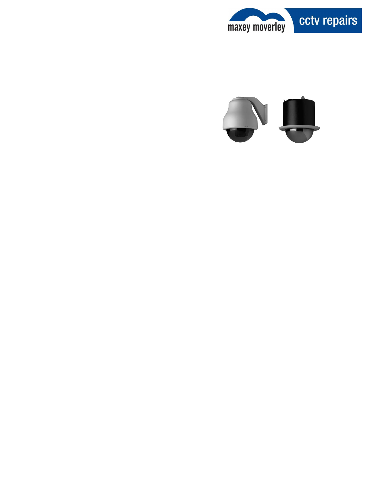
The receiver card mounted on the Power Domes pan/tilt contains a multi position DIP switch, as
seen elow. Use the switch to assign a camera num er to the Power Dome.
3.1 Dip Switch Positions & Equivalent Values
To program the receiver’s site num er on the DIP switch use the ta le elow:
Dip Switch Position Number 1 2 3 4 5 6 7 8 9 10 11 12
Equivalent Value 1 2 4 8 16 32 64 128 256 512 x x
If you use the PowerDome with coaxial UTC telemetry, we recommend that you set the address
especially if you plan to add a VPD-ALM16 alarm module.
If you use RS485 directly from a Vista NPX/KBD/J3De or VPD-KBD key oard that is also controlling
multiple Vista Triplex Colum us digital recorders or VDC1604 matrix units, address domes attached
to the units as follows:
•Unit with BaxNet address 1: 1 through 16
•Unit with BaxNet address 2: 17 through 32
•Unit with BaxNet address 3: 33 through 48
•Unit with BaxNet address 4: 49 through 64
For units with any other BaxNet address, domes should e num ered 1 through 16 and you should
use only one key oard.
When you use UTC control, each receiver needs to tune to the transmitter. Select each dome in turn,
and pan left and right until the dome moves. This should take a out 5 to 10 seconds.

Maxey Moverley Limited, 6 Broad Ground Road, Lakeside, Redditch, Worcestershire, B98 8YP
We : www.cctvrepairs.com ● Email: [email protected]
Tel: 01527 522299 ● Fax: 01527 522588
Issue 1.1 | Page 5
Quick Reference Guide
Vista PowerDome
4. Dip switches
One way to determine which switches to use is to su tract the highest possi le switch value from
the address you want, then su tract the highest possi le switch value from the difference. Continue
to su tract the highest possi le switch value from the difference until you have zero.
For example, if you want address 53:
Switch Address 53
Switch Address Switch Value Switch Values Switch On
53 - 32 = 21 6
2 - 16 = 5 5
5 - 4 = 1 3
- 1 = 0 1
Therefore, for address 53 you would use switches 1 (1), 3 (4), 5 (16), and 6 (32)
5. Technical Support Helpline
For help and guidance with installation issues, that are not covered within this guide please contact
our dedicated customer technical helpline on 0 527 522299 and speak to one of our specially
trained technicians will who will e happy to assist you.

Maxey Moverley Limited, 6 Broad Ground Road, Lakeside, Redditch, Worcestershire, B98 8YP
We : www.cctvrepairs.com ● Email: [email protected]
Tel: 01527 522299 ● Fax: 01527 522588
Issue 1.1 | Page 6
Quick Reference Guide
Vista PowerDome
6. Revision History
Revision
Date
Author
Amendments
Comments
1 24/04/13 DS First draft Issued for internal review
1.1 14/05/2013 DS Agreed format/content Issued for distribution
Table of contents
Popular Camera Accessories manuals by other brands

Photoflex
Photoflex FirstStudio DP-FSPTKT instruction sheet

Westcott
Westcott 1811 Setup instructions

Kaiser Fototechnik
Kaiser Fototechnik Tiltall BS-38 operating instructions

FocusShifter
FocusShifter DSLR Follow Focus operating instructions

Cyclopital3D
Cyclopital3D LPV owner's manual

Orion
Orion 5302 instruction manual