Maxima VRLA-AGM Original operating instructions

JUBILEE STORE L.L.C
Installation &
Operation Guide
VRLA-AGM
BATTERIES

JUBILEE STORE L.L.C
Page - 2 - of 23
CONTENTS
1. Introduction…………………………………………………………………………….3
2. Safety precaution and protection kits……………………………………………..3
3. Battery storage and using circumstances………………………………………..4
4. Using conditions…………………………………………………………………..…..4
5. Installation of batteries…………………………………………………………...…..4
6. Use of battery……………………………………………………………..….………...12
7. Battery maintenance ………………………………………………….….…………15
8. Exchange of Batteries………………..……………………………….….…………18

Page - 3 - of 23
Jubilee Store sealed lead acid battery is
battery according to the following instructions before use:
1. Introduction
Jubilee Store produces world-class batteries based on years of research and development. Our products
are manufactured under the guidelines of ISO9001 quality system. Each battery undergoes a series of
strict manufacturing and quality control processes before shipment. We are committed to provide our
customers the best batteries, with 100% customer satisfaction. We believe that the Jubilee Store battery
is the ideal selection for your application and your ultimate DC power choice.
2. Safety precaution and protection kits
When working any battery system, be sure you have the necessary tools and safety equipment,
including but not limited to:
¾insulated tools
¾rubber apron and gloves
¾face protection/face shield
¾safety goggles
¾fire extinguisher
¾emergency eye wash and shower, if available
¾acid spill cleanup kit
Pay attention to the electrical warning symbols to avoid serious injury or death caused by electrical
shock or burns.
Multi-cell battery systems can attain high voltage and/or currents. Do NOT touch un-insulated
batteries, connectors or terminals. To prevent serious electrical burns and shock, use EXTREME
CAUTION when working with the system
Always wear safety protection clothes and protect all exposed skin and eye surfaces
Use non-conductive or insulated tools when working with ANY battery system.
All installation tools should be adequately covered with vinyl electrical tape or suitable no-conducting
material to minimize the possibility of shorting across connections.
Never lay tools or other conductive objects on the battery.
Avoid any possible reasons for shorting, explosions and personal injury.
Do NOT throw away any batteries or battery components, they are recyclable resources.
JUBILEE STORE L.L.C
shipped charged, handle
the

Page - 4 - of 23
3. Battery storage and using circumstances
Storage
¾If the battery has high temperature or poor ventilation during storage and delivery, self-
discharge will be increased. Therefore, keep good ventilation and keep away from fire, flame,
water and heat supply etc.
¾When storing the battery, disconnect charger and load, Store in dry and cool conditions.
¾After storing for any certain time, please charge the batteries before use.
Using circumstances
¾No fire, flame or heat supply should be near the battery;
¾Avoid operating near heat supply and in direct sunlight;
¾Avoid operating in humid / damp locations;
¾Do not operate in sealed enclosed or without ventilation.
4. Using conditions
Temperature range:
¾Charging : 0 ~ +400C,
¾Discharging : -20 ~ +550C,
¾Storage : -15 ~ +500C;
Parallel connection : recommended within 4 groups;
Multilayer installation : temperature among layers should be controlled within 3degC;
Heat dispersing : maintain 20mm inter-bloc distance between batteries.
Ventilation : Ensure batteries are stored and used in ventilated conditions.
Optimum ambient temperature : +50C ~ +350C.
Float charge (25℃) : limited current ≤0.30C10, voltage 2.23~2.30V/cell
Equalizing charge (25℃) : limited current ≤0.30C10, voltage 2.30~2.40V/cell
Mixing batteries : Do not mix new and old batteries, batteries from
Different manufacturers, if required consult Jubilee Store
technical support.
JUBILEE STORE L.L.C

Page - 5 - of 23
5. Installation of batteries
5.1 Unpack and check
Delivery: Prevent any force on the terminal; do not tamper with any seals.
Do not place upside down, Do not throw or cause any impact to the battery;
Do not cause any metallic short circuit.
Inspection: packaging / appearance of battery for signs of damage;
Check parts list: battery quantity; accessories;
Reference: catalogue; installation drawing; other notices.
5.2 Notices before Installation
If no abnormity after check, install the batteries in the designated position;
If installing the batteries in the battery chamber, place them starting at the bottom of chamber;
Avoid installing the batteries near any heat supply such as transformers or heat exhaust of other
equipment;
A battery may cause flammable gas during storage, avoid enclosing with any apparatus which
produce flames / sparks
Before connecting, clean the terminals to bright metal.
Ensure that no conductive material can connect between positive and negative terminals.
Before installation all tools are insulated;
5.3 Installation and connection
Use insulated tools only;
Connect batteries, then connect battery group with charger or load;
When multi-group batteries are parallel connected, connect in series first and then parallel
connection;
To ensure good ventilation, the batteries per row should keep around 10 - 20mm inter-bloc spacing;
Before connection, clean the battery terminals to bright metal;
Before and after connection, apply antirust compound such as petroleum gel on the surface of
battery terminal;
After batteries are installed, test the voltage of the battery group, if correct link battery to load.
Use correct torque on all terminals, ensuring every connecting nut and screw is secure; see torque
settings as table 1
Table 1 Suggested torque table
JUBILEE STORE L.L.C

Page - 6 - of 23
S/N Range Torque
1 M5 2.0~3.0N*m(20~30kgf*cm)
2 M6 3.9~5.4 N*m(40~55kgf*cm)
3 M8 11~14.7N*m(111~150kgf*cm)
5.4 Pre Installation Check
Floor bearing: Batteries are heavy check the floor loading is not exceeded. Check rack/enclosure
complies with any load spread requirement.
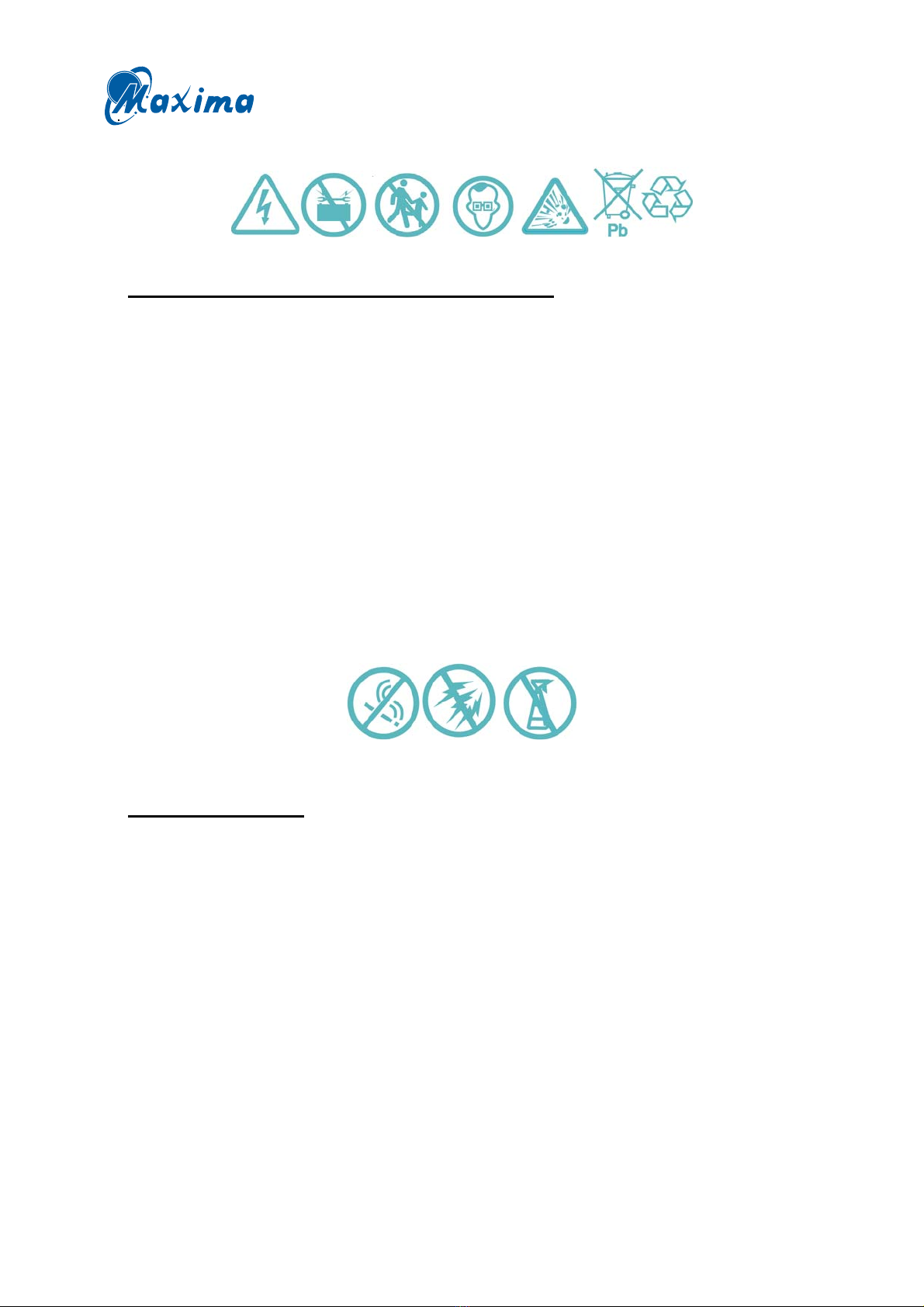
5.5 Battery rack assembly
example
follow the procedures below:
Step 1 : Insert cross bolt from bottom to up into lower-layer backstop steel hole of lateral frame,
then put lateral frame vertically.
Step 2 : Set under layer on the screw of lateral frame, lock the nut (notice not too tight).
Step 3 : Put the upper layer crosspiece between two lateral frame, fix them with M8*25 bolt
(notice not too tight);
JUBILEE STORE L.L.C
To Assemble a battery rack,

Page - 7 - of 23
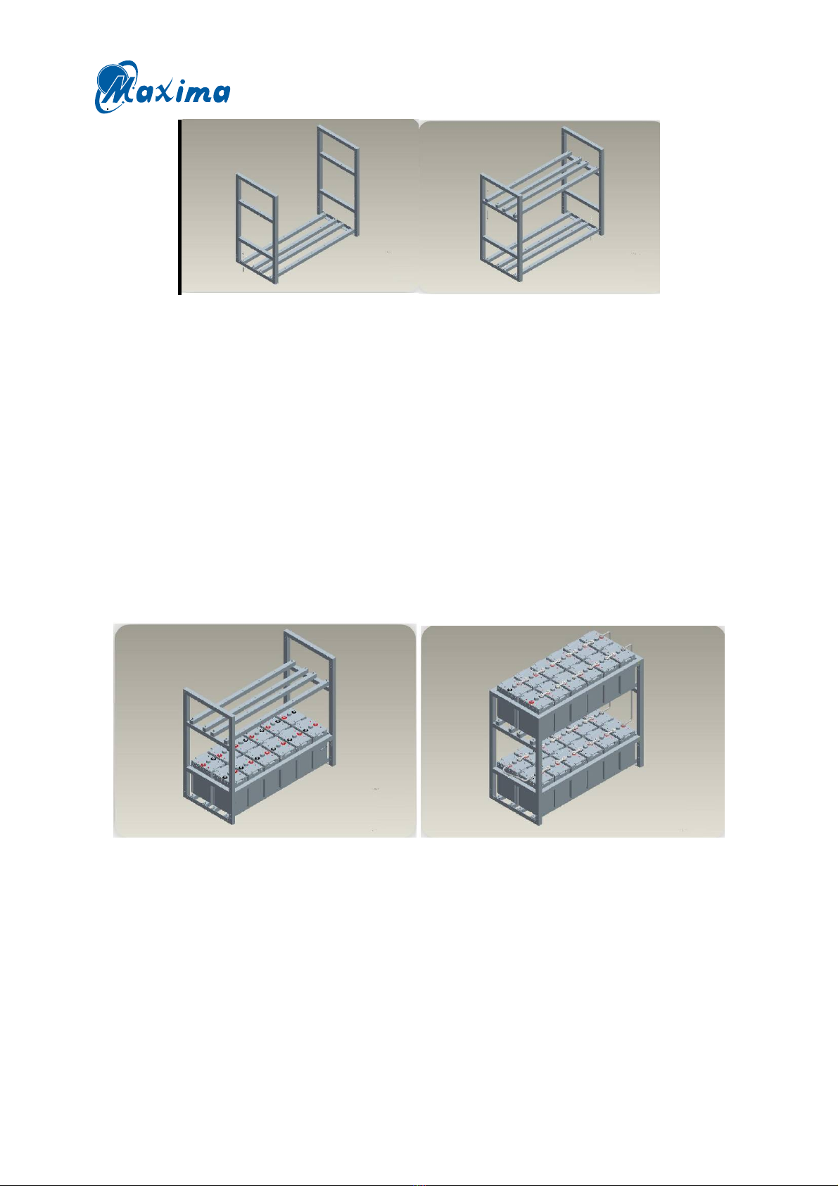
Step 4 : Collate the four angles of rack with tape measure to make sure that the rack is upright
and stable, then tighten the connection bolt between upper-layer pallet lateral frame and
under-layer pallet lateral frame;
Step 5 : Move and fix middle-empty rack to the appointed place. Mark the four holes with aiguille,
then move rack away and dig vertically to 55mm from the mark point with percussive
drill. Nail finestra with M8*70 floor hole bolt. Strain it with spanner. Remove rack.
Put wrench directly into four holes. Install nut and tighten it.
Step 6 : According to connection plan, start installing battery from bottom (notice the polarity as
placing batteries), use to separate batteries. Once finish installing a level, tighten bar to
lateral frame with M8*16 bolt.
Step 7 : According to connection plan, install connector and component, if there is a junction box,
refer to junction box installation specification.
Note : junction box installation instructions
JUBILEE STORE L.L.C

Page - 8 - of 23
¾Fix 2 high-voltage porcelain on the middle part of connection plate with hexagon bolt (M10*25).
¾Place connection plate and connection copper bar to parallel station, be close to high-voltage
porcelain; Hexagon bolt was put through the 2 central holes of copper bar, which fastening copper
bar on the porcelain.
¾Place connection plate and 2 shield supporting plate vertically, be close to connection plate.
¾Lift junction box be up close to corresponding site of shelf, and fastened with hexagon bolt.
¾After connecting strings, paste P/N on in the middle part of glass cover and plug the cover into
opposite groove of shield supporting plate.
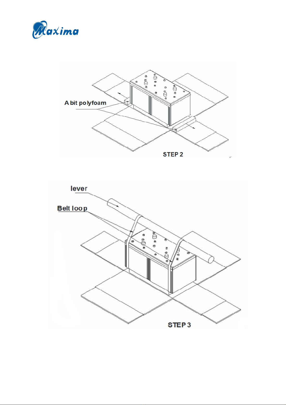
5.6 Batteries mounting on racks
Rack mounted Jubilee Store batteries follow the procedures below:
Step 1 : Carry batteries close to the rack, and then tear the box along its four corners.
JUBILEE STORE L.L.C

Page - 9 - of 23
Step 2 : Remove all bit poly-foams out from the bottom of the battery.
Step 3 : Hitch the battery with belt loops from the bit poly-foams, and then let the lever through
the belt loop.
JUBILEE STORE L.L.C

Page - 10 - of 23
Step 4 : Carry the battery up to the top of baffle.
Step 5 : Put the battery close to a side for a little gap and remove loops out.
STEP 4
JUBILEE STORE L.L.C

Page - 11 - of 23
5.7 Example Images after Installation
5.7.1 12V Battery Vertical Double-tier Rack (8 batteries)
5.7.2 12V Battery Vertical Tri-tier Rack (30 batteries)
JUBILEE STORE L.L.C

Page - 12 - of 23
1) 12V FT Battery Vertical Double-tier Cabinet (8 batteries)
2) 2V Battery Vertical Double-tier Tri-rank Rack (24 batteries)
JUBILEE STORE L.L.C

Page - 13 - of 23
6 Use of battery
6.1 Supplementary charge
During the delivery and storage, the battery will lose part of the capacity due to self discharge, so
please supplement charge before use;
If storage occurs before installation / connection, supplement charge regularly;
Supplementary charge according table 2 below before use:
Table 2 the time interval of supplementary charge and storage temperature
Storage
temperature
Time interval of
supplementing
charge
Supplementing charge way
200C or less Every 9 months a) Charging at a constant voltage of 2.23-
2.30V/cell and initial current to be less than 0.3C (A) for 2-3
days
b) Charging at a constant current of 0.3C(A) and a constant
voltage of 2.30-2.40V/cell for 10-16 hours
c) Charging at a constant of 0.1C(A) for 8-10 hours
Three options for choice
200C ~300C Every 6 months
300C ~400C Every 3 months
Note:
Current value C is rated capacity of battery.
Example: rated capacity of 2V300AH battery is 300AH, 0.1C (A) = 0.1X300 = 30A;
6.2 Discharge
Ensure the maximum allowable discharge current does not exceed the value below:
¾discharge current I≤1C10 (A),continuous discharge;
¾discharge current I=3C10 (A),discharge time T≤2min;
¾discharge current I=6C10 (A),discharge time T≤10s.
Final discharge protective voltage as table 3 below:
Table 3 Final discharge voltage
Note: 1) Do not let terminal voltages drop below the above specified values
2) Do not store after discharge, re-charge immediately
Discharge
rate
Current of
discharge(A)
Final discharge voltage
(V/cell) Testing standard of capacity
10h 1.0I10 1.8 ≥1.00C10
5h 1.7I10 1.8 ≥0.85C10
3h 2.5I10 1.75 ≥0.75C10
1h 5.5I10 1.75 ≥0.55C10
JUBILEE STORE L.L.C

Page - 14 - of 23
6.3 Capacity discharging test
Examples.
6.3.1 Off-system test method
a) Settle the battery group for 1 hour from the system after full charge, adopt the test load connect
method and proceed the discharge test at 10hours discharging rate under the ambient
temperature 25±50C .
b) Terminal voltage, ambient temperature, and start time should all be checked and recorded before
commencing discharge.
c) Terminal voltage, discharge current, room temperature should be checked and recorded
throughout the discharge period. Testing interval is 1 hour; discharge current shall not exceed
1% of the stipulated data. Reduce the time intervals to every 5mins as the test nears completion,
Or approaches end point voltages.
d) Discharge current multiplied by discharge time gives the capacity taken from the battery. When
battery discharge at 10hour discharging rate, if the temperature is not 250C, then it should be
calculated according to the below formula on the base of the capacity obtained in the test.
Ce = Cr/﹛1+K (t-250C )﹜
t-refers to the temperature;
K-refers to the temperature coefficient (K = 0.006/0C when discharging at 10H discharging rate,
K = 0.008/0C when discharge rate is 3H. K = 0.01/0C when discharge rate is 1H.)
e) Battery should be recharged by 1.1-1.3 times of the initial new specification
after finishing discharge.
6.3.2 On-system test method
a) In the direct current power system, adjust the out-put voltage of the inverter to protection voltage
(e.g.46V), battery supply the power to the load, then identify and test the battery with the lowest
voltage, and worst capacity.
b) Open the inverter and charge the battery, then wait 1hour after full charge.
c) Precede test at 10hour discharge rate on the worst battery identified in a). Terminal voltage,
temperature, discharge time, and room temperature should be tested and recorded before and
after the test and every hour. Notes should be taken at the moment the final voltage is showing to
record the discharge time accurately.
d) Discharge current * discharge time = capacity of the battery group. If the room temperature is not
250C, the capacity should be calculated according to the formula in (A).
JUBILEE STORE L.L.C

Page - 15 - of 23
e) After finishing the test, re-charge the battery to recover its capacity.
f) Draw the discharge curve according to the test data.
6.3.3 Check-aimed discharge test method
In order to control the estimated capacity of the battery group at any time, it is necessary to carry out the
check-aimed discharge test.
a) In DC power supply system, adjust the output voltage of the rectifier to protection voltage (for
example 46V), and the battery supply electricity to communication load. Terminal voltage,
temperature, room temperature and discharge time of the single battery should be tested and
recorded before and after the battery discharge. Until 30-40% of the rated capacity is released.
b) Re-charge the battery after finish discharge, the charged value should be 1.2times that of the
discharged value.
c) Draw discharge curve according to the notes, and keep record for comparing with future test.
Remark:
1) Off-system test method is not recommended for UPS system battery group.
2) When operating the on-system test method and check-aimed capacity test, if the tested UPS
equipment equipped with discharge performance itself, the test performance of discharging
should be opened. If it is without discharge test performance, its AC input should be
disconnected before proceeding with discharge test.
Note:
1) The above mentioned capacity test are the most frequently used in daily maintenance, but
whatever method is used, it is very important to keep a feed to the system during the test
period. Therefore, before processing the test, we should investigate whether there is plan to
stop electricity and the standby generator should be ready to work at any time.
2) Apply multi meter, inner-resistant instrument, conductance instrument to make a definitive
test before the capacity discharge test.
3) In order to make sure that accuracy of the capacity test, professional on-system test
instrument and test load should be adopted.
6.3.4 Judgment on lagged battery
Terminal voltage of the laggard battery is lower, so it should be tested under the discharging condition. If
the terminal voltages are lower on the average during the three continuing discharging cycle test, it can
be judged as the laggard battery of the group. Equalizing charge should be applied when laggard battery
is identified
JUBILEE STORE L.L.C

Page - 16 - of 23
6.4 Charge
6.4.1 Float charge
Charge parameter
Charge voltage: 2.23 ~2.30V/cell(250C)
The maximum charge current: 0.30C10
Temperature compensation coefficient: -3mV/cell (taking 250C as base point)
Total variation range of charge voltage is ±0.02V/cell
Note:
1) All cell/bloc voltages of a battery group have a little difference at the beginning of use, half
year later they become matched.
2) Effect from too high float voltage or too low float voltage as below:
Too high for a long time (overcharge): life shortened
Too low for a long time (not charge enough): Cannot meet load and/or make battery voltages
inconsistent. The battery group capacity will drop accordingly and life is shortened.
6.4.2 Cycle use charge
Charge parameter
Charge voltage: 2.40 ~2.50V/cell(250C)
The maximum charge current: 0.30C10
Temperature compensation coefficient: -5mV/cell (taking 250C as base point)
Total variation range of charge voltage:±0.02V/cell
Supplementary charge capacity is 110% ~ 130% of discharge capacity, ambient temperature is
below 50C, if do not know how many discharge capacity, please refer to the following table to
supplementary charge:
Table 4 Supplementary charge
Ambient temperature (℃) Charge voltage (V/cell) Charge time (h)
5 2.31 7
2.46 4
20 2.25 7
2.40 4
35 2.21 7
2.34 4
Note:
1) Charge time is the time when terminal voltage reaches value as the above table shows
during charging at a constant 0.30C (A) or less.
JUBILEE STORE L.L.C

Page - 17 - of 23
2) If the charge time is over the time as above table, it will cause over charge, which will
shorten the life of the batteries; if the charge time is less than the time as above table, the
batteries can not meet the normal capacity.
6.4.3 Equalization charge
Charging parameter
Charging voltage : 2.35 ~ 2.40V/cell (250C)
Maximal charging current : 0.30C10
Temperature equalization parameter : -3mV/cell(250C)
Variation scope of charging voltage : ±0.02V/cell
Note:
Do not carry this operation under standard float charging. Adopt equalization charging under below
situations:
¾Discharging capacity is above 20% of rated capacity.
¾Lay aside the battery without using it for more than 3 months.
¾Float voltage of battery unit is less than 2.18V/cell
¾Continuously float charging battery for 3 ~ 6 months or low voltage batteries appears in
battery group.
¾More than 1 year fully under float operation
¾Supplementary charge the battery after installation and before using.
¾Equalizing charge the battery after the capacity test.
6.4.4 Notes during charging
Charge current at the end of charge is over 0.05 C10A, which may result in permanent damage on
battery appearance and battery life; pay more attention to charging voltage.
The used charger should have digressive automatic constant voltage device, please contact us if
use other kind of charger.
If the ambient temperature is not 250C , temperature compensation should be applied on the voltage,
using the formula is U=U250C - K×(T -25)
T—ambient temperature; K—temperature compensation coefficient
Judgment on charge end point, usually, if the battery charge can meet any one of the below listed
condition, it can be regarded as the charge end point.
a) Charged value is not less than 1.2 times of the released value.
b) The current is less than 0.005C10A (C10 = rated capacity of the battery) during the final
period of charging.
c) The current is steady for 5 hours during the final period of charging.
JUBILEE STORE L.L.C

Page - 18 - of 23
7 Battery maintenance
7.1 Cleanness
Keep the battery surface and its working circumstance clean and dry.
Keep battery clean and avoid static condition.
Clean battery with damp cloth avoiding contact with terminals, no organic solvent such as gasoline,
alcohol etc. or clothes with such substance should be used to clean battery.
7.2 Inspection and maintenance
To better understand the operation of battery and equipment and also to prevent battery damage during
maintenance inspection, please periodically inspect the battery and record it
7.2.1 Inspection items per month:
Items Contents Standards Maintenance
Total float
charging
voltage of
battery group
Measure output end
voltage of positive
and negative end of
battery group with
voltage meter.
1. tested data comply with the
data displayed on the
meter and meet the voltage
standard under the
temperature conditions
2. The error of float charge
voltage after temperature
compensation Is ≤±50mV
1. If data attained by testing is varies
from the standard, the tested data
should prevail.
2. For those adjusted by monitor module
and still can’t reach the allowed error
range after module adjustment, repair
is to be applied or send them back to
factory.
Battery
appearance
Inspect battery case
and cover for bulge,
leakage or damage.
Normal Find out the reasons if abnormal
appearance exist, please change battery
if it effects the normal use of battery group
Inspect for dust or
stains
Clean Clean the dust and stain with damp
cloth.
Inspect the harness
and terminal for rust
or corrosion.
No rust Clean the rust, change the harness and
paste with antirust coating/paste.
Temperature
of the battery
Test the
temperature of the
terminal and battery
surface by infrared
thermometer
Under 35℃Determine reason for temperature being
above standard value and proceed on
relevant course of action.
JUBILEE STORE L.L.C

Page - 19 - of 23
Connection
Parts
Check the tightness
of terminal
bolt/screw with
torque spanner
Fastness please refer to the
table of torque)
Tighten the loosen bolt/screw in time
Check the
connection cable
and terminals for dirt
and corrosion
Without appearance of corrosion
or dirt
Take out the connection cable and clear it
in water if it is light corrosion, for serious
corrosion please replace the cable and
clear the connection point with a steel
brush before attaching new connectors
check safety
valves
(2V series)
Shake the valve
lightly to check the
valve is fixed tightly.
Valve is fixed tightly.Please tighten the value if there is
appearance of looseness
Cover the valve with
bubble liquid(soap
solution) to check if
the valve can
exhaust gas cleanly
Staggered air bubble appears The frequent tighten the valve if there is
appearance of open and close the value
is abnormal, in case happens, please
replace the valve at the same time,
please check the water lost status of the
battery.
Switch DC
power supply
Cut off AC power
supply and change
to UPS or DC power
supply
AC power supply switch to UPS
or DC power supply smoothly
Correct the potential difference
7.2.2 Inspection items per quarter
Apart from the maintenance per month, additional articles added as below:
Items Contents Standards Maintenance
Float voltage
of each battery
Measure the end voltage of each
battery in battery group.
Float voltage value after
temperature
equalization ±50mV
If float voltage is over standard value,
please apply equalization charge the
battery group after discharging them
and then float charge them for 1~2
month, please contact us if still have
any deviation from standard.
JUBILEE STORE L.L.C

Page - 20 - of 23
Repair
batteries
which with
laggard single
cell
1. Equalization charge of the
battery group: charge the battery at
upper limit voltage and last more
than 10H, 3 times of discharge
cycle is necessary when case is
serious.
The difference of float
charge voltage between
single cell in a group of
battery should meet the
below standard:
2Vseries 90mv
6vseries 240mv
12Vseries 480mv
Single cell should be replaced if it
fails in repair.
2. On-line repair of single cell:
connect the cell the activation
meter or charger with the laggard
battery and charge the single cell.
Activation
charge and
discharge
Charge and discharge the battery
by one cycle, then charge the
battery by the lower limit of the
equalization voltage
About 30% of the rated
capacity is released.
Produced this text on the batteries
which float charge more than 6moths
but without discharge.
7.2.3 Inspection item per year
Apart from the maintenance per quarter, additional articles added as below:
Items Contents Standards Maintenance
Checking
discharge test
Cut off AC power supply,
discharge battery with load,
and discharging 30%~40%
rated capacity.
Battery voltage should
be over 1.90V/cell
after discharging.
If battery voltage is lower than standard
value, please equalization charge the battery
group after discharging and then float
charging it for 1~2 month, please contact us
if still have any departure.
Capacity test
Adopt the on-system
capacity test instrument or
fake load discharge battery
and discharge 60~80%of
the rated capacity
More than 80% of the
capacity is reserved.
Take down the parameters during the
discharging test, if any laggard battery is
found, please proceed to relevant operation.
7.2.4 Basic requirements and cautions on maintenance
Requirements:
1) Principle “find out the hidden trouble and insure the safety” Should be complied when make test
on the battery.
2) Daily maintenance and performance analysis should be carried out strictly according the
processing plan.
3) Battery parameter setting operation should be strictly complied with the maintenance rules and
related requirement.
JUBILEE STORE L.L.C
Table of contents