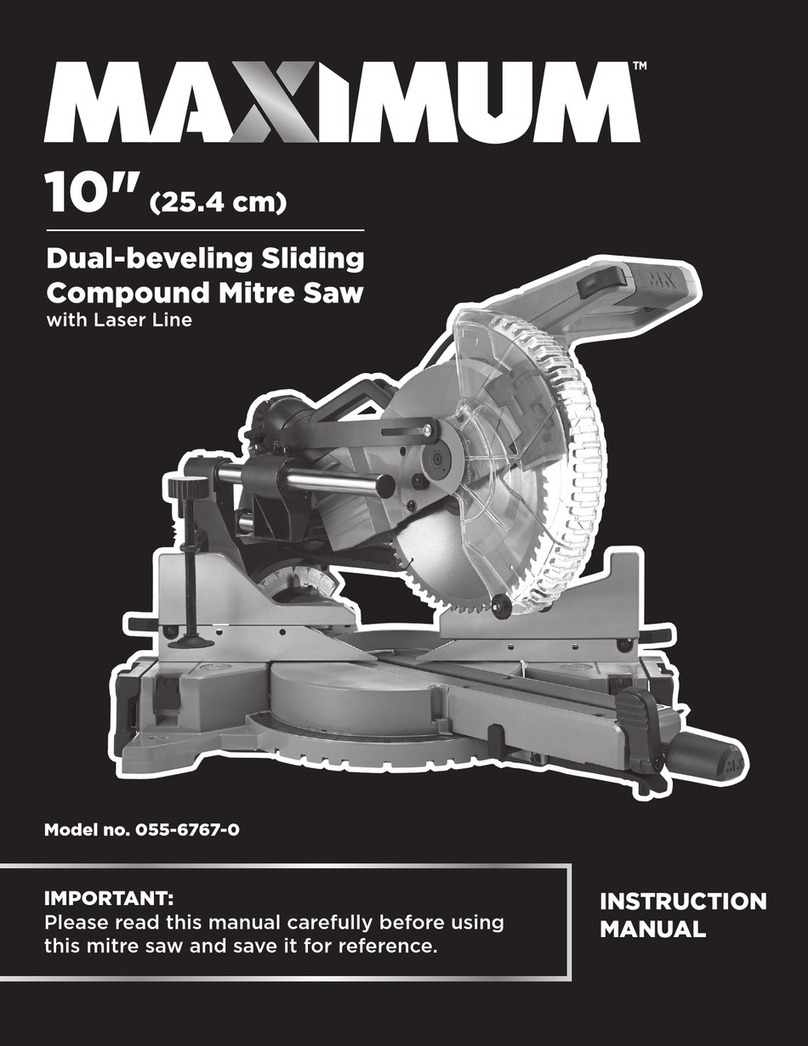
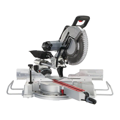
Maximum MS10300 User manual


3
TABLE OF CONTENTS
NOTE: If any parts are missing or damaged, or if you have
any questions, please call our toll-free helpline at 1-888-670-6682.
SAVE THESE INSTRUCTIONS
This manual contains important safety and operating
instructions. Read all instructions and follow them when
using this product.
TABLE OF CONTENTS
Quick start guide
Specifications
Safety guidelines
Know your mitre saw
Assembly
Operation
Maintenance
Troubleshooting
Exploded view
Parts list
Warranty
4
5
6
15
20
43
64
67
68
72
77

2
1
2
5
SPECIFICATIONS
4
QUICK START GUIDE
To turn the mitre saw on, lift the
lock off button to right,depress
the ON/OFF switc located in
the switch handle .
This sliding mitre saw is designed to cut wood and wood composition products only.
The tool can be used for the mitre cut, slide cuts, crosscut, bevel cut and compound
mitre cut.
CAUTION!
• Read and understand the following instructions to get the
best use of the mitre saw cutting function.
Motor
Speed
Blade
Arbour size
Bevel adjustment
Mitre adjustment
Max. cutting capacity
Weight
120 V, 60 Hz, 15A
4200/min (no-load)
10" (25.4 cm) 60-tooth carbide-tipped
5/8" (1.6 cm)
0–48 degree left and right
50 degree left and 60 degree right
3 x 12 1/2" (7.6 x 32 cm) at 0° mitre;
3 1/2 x 11 29/32" (8.9 x 30.2 cm) at 0° mitre;
3 x 8 29/32" (7.6 x 22.6 cm) at 45° mitre;
3 1/2 x 8 13/32" (8.9 x 21.3 cm) at 45° mitre;
1 51/64 x 12 1/2" (4.6 x 32 cm) at 45° bevel left;
2 13/64 x 11 29/32" (5.6 x 30.2 cm) at 45° bevel left;
51/64 x 12 1/2" (2.0 x 32 cm) at 45° bevel right;
1 x 11 29/32" (2.5 x 30.2 cm) at 45° bevel right
91 lb 8 oz (41.5 kg) with stand
SPECIFICATIONS
•
To turn it off, release the ON/OFF
switch 1 .
see page 44.
•
Lower the saw head all the way
down, and cut through the edge of
the workpiece.
Push (but do not force) the saw
head towards the fence all the way
to the rear position to complete
the cut.
see page 49.
•
•
2
1
3
1
model no. 055-9034-6 | contact us 1-888-670-6682
TURNING SAW ON(1)
(2)
TURNING SAW OFF
3
1

7
SAFETY GUIDELINES
6
SAFETY GUIDELINES
WARNING!
To avoid mistakes that could cause serious injury, DO
NOT plug in the mitre saw until you have read and
understood the rules.
SAFETY GUIDELINES
This manual contains information that relates to PROTECTING PERSONAL SAFETY and
PREVENTING EQUIPMENT PROBLEMS. It is very important to read this manual carefully
and understand it thoroughly before using the product. The symbols listed below are
used to indicate this information.
Do not operate power tools in explosive atmospheres, such as in the presence of
flammable liquids, gases or dust. Power tools create sparks which may ignite the dust
or fumes.
Keep children and bystanders away while operating a power tool. Distractions
can cause you to lose control.
Power tool plugs must match the outlet. Never modify the plug in any way. Do not use
any adaptor plugs with earthed (grounded) power tools. Unmodified plugs and
matching outlets will reduces risk of electric shock.
Avoid body contact with earthed or grounded surfaces, such as pipes, radiators,
ranges and refrigerators. There is an increased risk of electric shock if your body is
earthed or grounded.
Do not expose power tools to rain or wet conditions. Water entering a power tool will
increase the risk of electric shock.
Do not abuse the cord. Never use the cord for carrying, pulling or unplugging the
power tool. Keep cord away from heat, oil, sharp edges or moving parts. Damaged or
entangled cords increase the risk of electric shock.
When operating a power tool outdoors, use an extension cord suitable for outdoor use.
Use of a cord suitable for outdoor use reduces the risk of electric shock.
If operating a power tool in a damp location is unavoidable, use a ground fault circuit
interrupter (GFCI) protected supply. Use of an GFCI reduces the risk of electric shock.
Stay alert, watch what you are doing and use common sense when operating a power
tool. Do not use a power tool while you are tired or under the influence of drugs,
alcohol or medication. A moment of inattention while operating power tools may result
in serious personal injury.
Use personal protective equipment. Always wear eye protection. Protective equipment
such as a dust mask, non-skid safety shoes, hard hat, or hearing protection used for
appropriate conditions will reduce personal injuries.
Prevent unintentional starting. Ensure the switch is in the off-position before
connecting to power source and/or battery pack, picking up or carrying the tool.
Carrying power tools with your finger on the switch or energising power tools that have
the switch on invites accidents.
Remove any adjusting key or wrench before turning the power tool on. A wrench or a
key left attached to a rotating part of the power tool may result in personal injury.
Do not overreach. Keep proper footing and balance at all times. This enables better
control of the power tool in unexpected situations.
Dress properly. Do not wear loose clothing or jewellery. Keep your hair, clothing and
gloves away from moving parts. Loose clothes, jewellery or long hair can be caught in
moving parts.
DANGER!
Potential hazard that will result in serious injury or loss of life.
WARNING!
Potential hazard that could result in serious injury or loss of life.
WARNING!
Read all safety warnings, instructions, illustrations and specifications provided
with this power tool. Failure to follow all instructions listed below may result in
electric shock, fire and/or serious injury.
CAUTION!
Potential hazard that may result in moderate injury or damage to equipment.
Note: The word “Note” is used to inform the reader of something the operator needs to
know about the tool.
SAFETY RECOMMENDATIONS
These precautions are intended for the personal safety of the operator and others
working with the operator. Failure to follow these instructions may result in a permanent
loss of vision, serious personal or even fatal injury, property damage and/or tool
damage. Please take time to read and understand these instructions.
Safety is a combination of common sense, staying alert and knowing how your mitre saw
works.
GENERAL SAFETY RULES
Keep work area clean and well lit. Cluttered or dark areas invite accidents.
model no. 055-9034-6 | contact us 1-888-670-6682
Save all warnings and instructions for future reference.
The term “power tool” in the warnings refers to your mains-operated (corded) power
tool or or battery-operated (cordless) power tool.
1) Work area safety
•
•
•
2) Electrical safety
•
•
•
•
•
•
3) Personal safety
•
•
•
•
•
•

9
SAFETY GUIDELINES
8
SAFETY GUIDELINES
or held by hand. If your hand is placed too close to the saw blade, there is an increased
risk of injury from blade contact.
The workpiece must be stationary and clamped or held against both the fence and the
table. Do not feed the workpiece into the blade or cut “freehand” in any way.
Unrestrained or moving workpieces could be thrown at high speeds, causing injury.
Push the saw through the workpiece. Do not pull the saw through the workpiece. To
make a cut, raise the saw head and pull it out over the workpiece without cutting, start
the motor, press the saw head down and push the saw through the workpiece. Cutting
on the pull stroke is likely to cause the saw blade to climb on top of the workpiece and
violently throw the blade assembly towards the operator.
Never cross your hand over the intended line of cutting either in front or behind the
saw blade. Supporting the workpiece “cross handed", i.e., holding the workpiece to the
right of the saw blade with your left hand or vice versa, is very dangerous.
Do not reach behind the fence with either hand closer than 4" (10 cm) from either side
of the saw blade, to remove wood scraps or for any other reason, while the blade is
spinning. The proximity of the spinning saw blade to your hand may not be obvious
and you may be seriously injured.
Inspect your workpiece before cutting. If the workpiece is bowed or warped, clamp it
with the outside bowed face toward the fence. Always make certain that there is no
gap between the workpiece, fence and table along the line of the cut. Bent or warped
workpieces can twist or shift and may cause binding on the spinning saw blade while
cutting. There should be no nails or foreign objects in the workpiece.
Do not use the saw until the table is clear of all tools, wood scraps, etc., except for the
workpiece. Small debris or loose pieces of wood or other objects that contact the
revolving blade can be thrown with high speed.
Cut only one workpiece at a time. Stacked multiple workpieces cannot be adequately
clamped or braced and may bind on the blade or shift during cutting.
Ensure the mitre saw is mounted or placed on a level, firm work surface before use. A
level and firm work surface reduces the risk of the mitre saw becoming unstable.
Plan your work. Every time you change the bevel or mitre angle setting, make sure the
adjustable fence is set correctly to support the workpiece and will not interfere with
the blade or the guarding system. Without turning the tool on, and with no workpiece
on the table, move the saw blade through a complete simulated cut to assure there will
be no interference or danger of cutting the fence.
Provide adequate support such as table extensions, saw horses, etc., for a workpiece
that is wider or longer than the table top. Workpieces longer or wider than the mitre
saw table can tip if not securely supported. If the cut-off piece or workpiece tips, it can
lift the lower guard or be thrown by the spinning blade.
Do not use another person as a substitute for a table extension or as additional
support. Unstable support for the workpiece can cause the blade to bind or the
workpiece to shift during the cutting operation pulling you and the helper into the
spinning blade.
If devices are provided for the connection of dust extraction and collection facilities,
ensure these are connected and properly used. Use of dust collection can reduce
dust-related hazards.
Do not let familiarity gained from frequent use of tools allow you to become
complacent and ignore tool safety principles. A careless action can cause severe injury
within a fraction of a second.
Do not force the power tool. Use the correct power tool for your application. The
correct power tool will do the job better and safer at the rate for which it was
designed.
Do not use the power tool if the switch does not turn it on and off. Any power tool
that cannot be controlled with the switch is dangerous and must be repaired.
Disconnect the plug from the power source from the power tool before making any
adjustments, changing accessories, or storing power tools. Such preventive safety
measures reduce the risk of starting the power tool accidentally.
Store idle power tools out of the reach of children and do not allow persons unfamiliar
with the power tool or these instructions to operate the power tool. Power tools are
dangerous in the hands of untrained users.
Maintain power tools and accessories. Check for misalignment or binding of moving
parts, breakage of parts and any other condition that may affect the power tool’s
operation. If damaged, have the power tool repaired before use. Many accidents are
caused by poorly maintained power tools.
Keep cutting tools sharp and clean. Properly maintained cutting tools with sharp
cutting edges are less likely to bind and are easier to control.
Use the power tool, accessories, tool bits, etc., in accordance with these instructions,
taking into account the working conditions and the work to be performed. Use of the
power tool for operations different from those intended could result in a hazardous
situation.
Keep handles and grasping surfaces dry, clean and free from oil and grease. Slippery
handles and grasping surfaces do not allow for safe handling and control of the tool in
unexpected situations.
Have your power tool serviced by a qualified repair person using only identical
replacement parts. This will ensure that the safety of the power tool is maintained.
Mitre saws are intended to cut wood or wood-like products, they cannot be used with
abrasive cut-off wheels for cutting ferrous material such as bars, rods, studs, etc.
Abrasive dust causes moving parts such as the lower guard to jam. Sparks from
abrasive cutting will burn the lower guard, the kerf insert and other plastic parts.
Use clamps to support the workpiece whenever possible. If supporting the workpiece
by hand, you must always keep your hand at least 4" (10 cm) from either side of the
saw blade. Do not use this saw to cut pieces that are too small to be securely clamped
model no. 055-9034-6 | contact us 1-888-670-6682
•
•
4) Power tool use and care
•
•
•
•
•
•
•
•
5) Service
•
•
•
•
•
•
•
•
•
•
•
•
SAFETY INSTRUCTIONS FOR MITRE SAW
•
•
Double check that the accessories and attachments are properly attached.
Always hold the product by its handle. Keep the handle dry to ensure safe support.
Ensure that the air vents are always unobstructed and clear. Clean them if necessary
with a soft brush. Blocked air vents may lead to overheating and damage the product.
Switch the product off immediately if you are disturbed while working by other people
entering the working area. Always let the product come to complete stop before
putting it down.
Do not overwork yourself. Take regular breaks to ensure you can concentrate on the
work and have full control over the product.
THIS STAND WAS DESIGNED TO BE USED AS A STAND FOR MITRE SAW. Do not alter
the stand, use it with other products, or for other purposes. The stand will support
300 lb (136 kg) including both machine and workpiece. Any misuse or abuse can result in
product damage or personal injury.
USE CARE WHEN ASSEMBLING, MOVING, RAISING OR LOWERING THE STAND to
reduce the risk of pinching hands and fingers.
PLACE THE STAND ON A FLAT AND LEVEL SURFACE to prevent rocking or tipping. Do
not use the stand on an uneven, unstable or slippery surface. Always check the stability
of the stand before connecting machine to power source.
DO NOT STAND ON THIS PRODUCT or use the support extensions as a ladder or
scaffolding. It is unsafe to climb, sit or stand on this product.
CHECK PRODUCT FOR DAMAGE. Before using stand, and after it has been dropped or
damaged, check moving and affected components of stand and any attached machines
for alignment, binding, breakage and any other condition that may affect the machine’s
performance and the stand’s ability to properly support and secure the machine. Do
not use a damaged product. A damaged product should be properly repaired using
only identical replacement parts.
CHECK THE LEGS AND OTHER SUPPORTS to confirm that they are properly locked in
place before connecting machine to power source.
DISCONNECT MACHINE from power source before attaching it to stand, and when
machine is not in use.
PROPERLY MOUNT machine and adjust workpiece supports so the workpiece(s) will be
level with machine table.
PROPERLY SECURE THE MACHINE to the stand before connecting it to power source.
DO NOT ATTEMPT to use stand for operations involving awkward or oversized
workpieces that could cause the stand to tip over.
11
SAFETY GUIDELINES
10
SAFETY GUIDELINES
The cut-off piece must not be jammed or pressed by any means against the spinning
saw blade. If confined, i.e., using length stops, the cut-off piece could get wedged
against the blade and thrown violently.
Always use a clamp or a fixture designed to properly support round material such as
rods or tubing. Rods have a tendency to roll while being cut, causing the blade to
“bite” and pull the work with your hand into the blade.
Let the blade reach full speed before contacting the workpiece. This will reduce the
risk of the workpiece being thrown.
If the workpiece or blade becomes jammed, turn the mitre saw off. Wait for all moving
parts to stop and disconnect the plug from the power source. Then work to free the
jammed material. Continued sawing with a jammed workpiece could cause loss of
control or damage to the mitre saw.
After finishing the cut, release the switch, hold the saw head down and wait for the
blade to stop before removing the cut-off piece. Reaching with your hand near the
coasting blade is dangerous.
ADDITIONAL SAFETY WARNINGS FOR MITRE SAW
•
•
•
•
•
•
•
•
•
•
•
•
•
•
•
Use only saw blades recommended by the manufacturer for wood and analogous
materials.
Pay attention to the cutting capacities mentioned in the technical data.
Pay attention to the maximum bevel angle and mitre angle settings mentioned in the
technical data.
Use only a saw blade diameter that matches the markings on the saw and information
about the bore diameter and the maximum kerf of the saw blade.
Use only saw blades that are marked with a speed equal or higher than the speed
marked on the tool.
During blade changing procedure, the rotation direction arrow on the saw blade
should comply with the one on the upper fixed blade guard.
Pay attention to the setting device(s) and the locking device(s) for the mitre angle
and bevel angel mentioned in the controls.
Turn the lower retractable blade guard by hand to test if it is rotating smoothly.
Pay attention to how to connect dust extraction systems mentioned in assembly.
Pay attention to the cutting sequence mentioned in the operation.
Pay attention to the cutting depth for non-through cuts mentioned in the controls.
Ensure that the mitre saw is always stable and secure.
Always fix and use the extension supporter during operation.
Use additional supports if needed to ensure the stability of the workpiece.
The power tool shall not be wet or used in a wet environment.
Check the product, its power cord and plug as well as accessories for damage before
each use. Do not use the product if it is damaged or shows wear.
model no. 055-9034-6 | contact us 1-888-670-6682
•
•
•
•
•
•
•
•
•
•
•
•
•
•
•
•
•
•
•
•
SAFETY INSTRUCTIONS FOR STAND

Fig. 1
CAUTION!
Servicing of a product with double insulation requires
extreme care and knowledge of the system and should
be performed only by a qualified service technician.
For service, we suggest you return the tool to your
nearest authorized service centre for repair. Always
use original factory replacement parts when servicing.
Do not use power tools in wet or damp locations or
expose them to rain or snow.
WARNING!
Double insulation does not take the place of normal
safety precautions when operating this tool.
WARNING!
The double-insulated system is intended to protect the
user from shock resulting from a break in the tool’s
internal wiring. Observe all normal safety precautions
to avoid electric shock.
WHEN TRANSPORTING STAND, make sure it is properly secured to prevent movement
and possible damage.
SAFETY GUIDELINES
SAFETY GUIDELINES
1312
POWER REQUIREMENTS
This tool has a precision-built electric motor. It should be connected to a power supply
that is 120 volts, 60 Hz, AC only (normal household current). Do not operate this
product on direct current (DC). A substantial voltage drop will cause a loss of power
and the motor will overheat. If the tool does not operate when plugged into and outlet,
double check the power supply.
GUIDELINES FOR EXTENSION CORDS
Use a proper extension cord. Make sure extension cords are in good condition. When
using an extension cord, be sure to use a cord that is heavy enough to carry the drawn
current needed by the saw. An undersized cord will cause a drop in line voltage,
resulting in loss of power and overheating.
The table below shows the correct size to use depending on the cord length and
nameplate amperage rating. If in doubt, use the next heavier gauge. The smaller the
gauge number, the heavier the cord.
WARNING!
Do not permit fingers to touch the terminal or the plug
when installing or removing the plug from an outlet.
model no. 055-9034-6 | contact us 1-888-670-6682
•
DOUBLE INSULATION
Double insulation is a concept in safety in electric power tools, which eliminates the need
for the usual three-wire grounded power cord. All exposed metal parts are isolated from
the internal metal motor components with protecting insulation. Double-insulated tools
do not need to be grounded.
To reduce the risk of electric shock, double-insulated
tools are equipped with a polarized plug (one blade is
wider than the other). This plug will fit into a polarized
outlet only one way. If the plug does not fit, contact a
qualified electrician to install a polarized outlet. Do not
change the plug in any way.
USE SAFETY GOGGLES AND EAR PROTECTION
ALWAYS WEAR EYE PROTECTION THAT CONFORMS WITH CUL
REQUIREMENTS. FLYING DEBRIS can cause permanent eye damage.
The tool is loud and the sound can cause hearing damage. Always wear
ear protection to help prevent hearing damage and loss. Failure to
comply may result in moderate injury.
USE DUST MASK
Some dust created by sawing contains chemicals that are known to cause
cancer, birth defects or other reproductive harm. Some examples of these
chemicals come from lead-based paints, crystalline silica from bricks,
cement and other masonry products, and arsenic and chromium from
chemically treated lumber. To reduce exposure to these chemicals, work in a
well-ventilated area with approved safety equipment, such as dust masks that are
specially designed to filter out microscopic particles.
Danger! Keep hands away from blade

KNOW YOUR MITRE SAW
SAFETY GUIDELINES
1514
AMPERAGE RATING OF THE TOOL
(120 V CIRCUIT ONLY)
MORE THAN
0
6
10
12
NOT MORE THAN
6
10
12
16
25' (7.6 m)
18
18
16
14
50' (15.2 m)
16
16
16
12
100' (30.5 m)
16
14
14
Not recommended
150' (45.7 m)
14
12
12
TOTAL LENGTH OF THE EXTENSION CORD
MINIMUM GAUGE FOR THE EXTENSION CORD (AWG)
WARNING!
Check extension cords before each use. If damaged,
replace immediately. Never use tool with a damaged
cord since touching the damaged area could cause
electric shock resulting in serious injury.
WARNING!
Keep the extension cord clear of the working area.
Positon the cord so that it will not get caught on
lumber, tools, or other obstructions while you are
working with a power tool.
Failure to do so can result in serious personal injury.
WARNING!
To avoid electrical hazards, fire hazards, or damage
to the tool, use proper circuit protection.
Be sure extension cords are properly wired and in good condition. Always replace a
damaged extension cord or have it repaired by a qualified technician before using it.
Protect extension cords from sharp objects, excessive heat, and damp or wet areas.
Use a separate electrical circuit for power tools. This circuit must not be less than #
14 wire with a 15 Amp time-delayed fuse, and should be protected with a time-delayed
fuse. Before connecting the tool to the power line, make sure the switch is in the OFF
position and the electric current is rated the same as the current stamped on the motor’s
nameplate. Running at a lower voltage will damage the motor.
27
26
23
24
25
21
20
19
3
2
4
5
6
7
8
18
22
29 3028
13
481
1516
17
12
11
109
14
40
39
41
43
42
45
46
47
44
38
37
34
33
36
31
32
35
model no. 055-9034-6 | contact us 1-888-670-6682

KNOW YOUR MITRE SAW
KNOW YOUR MITRE SAW
1716
No.
1
2
3
4
5
6
7
8
9
10
11
12
13
14
15
16
17
18
19
20
21
22
23
24
25
Description
Mounting hole
Rail
Wrench
Fence lock knob
Back fence knob
Working table
Depth stop
Depth adjustment screw
Arbour lock
Trigger switch
Foot
Mitre latch lever
Mitre scale pointer
Mitre scale
Locking lever
Mounting bracket
Adjustable foot
Lower leg
Locking pin
Base
Extension rail
Sliding fence
Bevel scale
Bevel scale pointer
Head lock pin
No.
26
27
28
29
30
31
32
33
34
35
36
37
38
39
40
41
42
43
44
45
46
47
48
Description
Slide stop
Dust bag
Carbon brush cap
Carrying handle
Switch handle
Upper blade guard
Lower blade guard
Dust duct inlet
Workpiece clamp
Saw blade
Work support
Fence
Table insert
Mitre latch button
Mitre lock handle
Upper leg
Precision blade guide system's
ON/OFF switch
Motor
Slide bar
Slide lock knob
Power cord storage
Bevel lock knob
Bevel detent lever
15 AMP MOTOR
This saw has a powerful 15 amp motor with sufficient power to handle tough cutting jobs.
It is made with all ball bearings, and has externally-accessible brushes for ease of
servicing.
CARRYING HANDLE
Carry handle is located on the top of the cutting head.
DEPTH STOP
The depth stop allows the depth of cut of the blade to be limited. The depth stop is
useful for applications such as grooving and tall vertical cuts.
MITRE LOCK KNOB
The mitre lock knob securely locks the saw at the desired mitre angle.
MITRE SCALE
The mitre scale has ten positive stops at 0°, 15°, 22.5°, 31.6°, 45° (left & right) and 60°
(right).
BEVEL SCALE
The bevel scale has index points provided at 0°, 22.5°, 33.9° and 45° left and right.
LOWER BLADE GUARD
The lower blade guard is made of shock resistant, see-through plastic that provides
protection from each side of the blade. It retracts over the upper blade guard as the saw
is lowered into the workpiece.
SLIDE BAR
When unlocked, the saw arm will glide forward and backward the length of the slide bar
for cutting various workpiece widths.
SLIDE STOP
The slide stop control positions your slide bars so that the largest possible vertical
moldings can be cut. Always tighten the slide lock knob when using the slide stop to
prevent the slide system from moving unintentionally.
SLIDING FENCES
The sliding fences provided with this saw help hold the workpiece securely when
making most cuts. The sliding feature allows for clearance of the saw blade when making
bevel or compound cuts. Some cuts may require that the sliding fence be removed
completely to avoid interference between the fence and the blade.
ARBOUR LOCK PIN
A arbour lock pin has been provided for locking the arbour (keeping the saw blade from
turning). Depress and hold the lock pin only while installing, changing, or removing the
saw blade.
SLIDE LOCK KNOB
The slide lock knob locks and unlocks the sliding feature of this tool.
The safe use of this product requires an understanding of the information on the tool and
in this operator’s manual as well as a knowledge of the project you are attempting.
Before use of this product, familiarize yourself with all operating features and safety
rules.
10” (25.4 cm) BLADE
A 10” (25.4 cm) blade is included with your mitre saw. It will cut materials up to 12 1/2"
(32 cm) wide, depending upon the angle at which the cut is being made.
model no. 055-9034-6 | contact us 1-888-670-6682

18
KNOW YOUR MITRE SAW
KNOW YOUR MITRE SAW
19
THROUGH SAWING
Any cutting operation where the blade extends completely through the thickness of the
workpiece.
BEVEL CUT
A cutting operation made with the blade at any angle other than 90° to the table surface.
MITRE CUT
A cutting operation made with the workpiece at any angle other than 90° to the blade.
COMPOUND CUT
A crosscut made with both a mitre angle and a bevel angle.
WORKPIECE CLAMP
The workpiece clamp is mounted on the left or right base to securely clamp the
workpiece.
BASE
Supports the table, holds accessories and allows for workbench or leg set mounting.
MITRE LOCK HANDLE
Used to rotate the table, and to rotate the saw to a right or left cutting position.
MOUNTING HOLES
To mount the mitre saw to a stable surface.
TRIGGER SWITCH
To start the tool, squeeze the trigger. Release the trigger to turn off the mitre saw.
HEAD LOCK PIN
Locks the mitre saw in the lowered position for storage and transportation.
SWITCH HANDLE
The switch handle contains the trigger switch. The blade is lowered into the workpiece
by pushing down on the handle. The saw will return to its upright position when the
handle is released.
WRENCH
One end of the wrench is a socket wrench and the other end is a flower wrench with size
T30. It is used for changing the blade and adjusting the tension when replace the belt.
The storage area for the wrench is located in the rear of base.
WRENCH STORAGE
Convenient storage to prevent misplacing the wrench.
ARBOUR
The shaft on which a blade is mounted.
ARBOUR LOCK
Allows the user to stop the blade from rotating while tightening or loosening the arbour
bolt during blade replacement or removal.
WORKPIECE
The item being cut. The surfaces of a workpiece are commonly referred to as faces, ends
and edges.
TABLE INSERT
A plate inserted in the mitre saw’s table that allows for blade clearance.
NON-THROUGH CUT
Any cutting operation where the blade does not extend completely through the
thickness of the workpiece.
model no. 055-9034-6 | contact us 1-888-670-6682

PACKAGE CONTENTS
For stand
For mitre saw
No. Description Qty. Illustration
Stand assembly A
Stand assembly B
Lower leg
1
2
3
Work support
Mounting bracket
4
5
6
7
Round-head square-neck screw
M8 x 55 mm
1
1
4
1
2
Locking nut M88 12
4
Round-head square-neck screw
M8 x 45 mm 8
No. Description Qty. Illustration
Mitre saw assembly
Left extension rail
1
2
1
1
No. Description Qty. Illustration
Hex bolt M6 x 55 mm9 4
Flat washer 610 4
Spring washer 611 4
Plastic washer12 4
Nut13 4
5 mm Hex key14 1
20
ASSEMBLY
ASSEMBLY
21
model no. 055-9034-6 | contact us 1-888-670-6682

No. Description Qty. Illustration
Wrench
(in wrench storage)
Workpiece clamp4
Right extension rail3
5
Dust bag6
1
1
1
1
ASSEMBLY
ASSEMBLY
2322
model no. 055-9034-6 | contact us 1-888-670-6682
Screwdriver
Triangle square Framing square
Star-head screwdriver
10 mm, 13 mm
open-end wrench or
adjustable wrench
Flower wrench
T20, T25
WARNING!
The use of attachments or accessories not listed in this manual might be
hazardous and could cause serious personal injury.
TOOLS NEEDED FOR ASSEMBLY
UNPACKING
This product requires assembly.
•
•
•
•
•
•
•
This saw has been shipped with the mitre table 60° right and saw head 0° and with the
saw head secured in the down position.
To release the saw head, push down the switch handle and pull out the head lock pin.
Raise the saw head by the handle. Hand pressure should remain on the switch handle
to prevent sudden rise upon release of the head lock pin.
Inspect the tool carefully to make sure that no breakage or damage occurred during
shipping.
Do not discard the packing material until you have carefully inspected and satisfactorily
operated the tool.
The saw is factory set for accurate cutting. After assembling it, check for accuracy. If
shipping has influenced the settings, refer to specific procedures explained in this
Operator’s Manual.
If any parts are damaged or missing, please call 1-888-670-6682 for assistance.
•
•
Carefully remove the stand and all parts from the carton.
Carefully lift saw from the carton by the carrying handle located at the top of the saw
body, and place it on a level work surface.
CAUTION:
This tool is heavy. To avoid back injury, lift with your legs, not your back, and
get help when needed.
WARNING!
Do not attempt to modify this tool or create accessories not recommended for
use with this tool. Any such alteration or modification is misuse, and could result in a
hazardous condition leading to possible serious personal injury.
WARNING!
Do not connect to the power supply until assembly is complete. Failure to
comply could result in accidental starting and possible serious personal injury.
WARNING!
Do not start the mitre saw without checking for interference between the saw
blade and the sliding fences. Damage could result to the blade if it strikes the sliding
fence during operation of the saw.
WARNING!
Always make sure the mitre saw is securely mounted to a workbench or
approved workstand. Failure to heed this warning can result in serious personal injury.
WARNING!
Many of the illustrations in this manual show only portions of the mitre saw. This
is intentional so that we can clearly show points being made in the illustrations. Never
operate the saw without all guards securely in place and in good operating condition.

ASSEMBLY
ASSEMBLY
2524
model no. 055-9034-6 | contact us 1-888-670-6682
Fig. 2a
Fig. 2b
Fig. 2c
Fig. 2d
Fig. 2e
Fig. 2f
ASSEMBLING THE STAND (FIG. 2a-2i)
•Lay the stand assembly A (1) and the stand
assembly B (2) top down on the floor with
the upper legs (3) on top.
Insert the stand assembly A tubes into the
stand assembly B tubes. Align the holes on
the stand assembly A (1) with the stand
assembly B (2).
•Insert the round head square neck screws
M8 x 55 mm (4) through the holes and
tighten with locking nuts M8 (5).
•Push in a locking pin (6) on the upper leg (7)
and rotate that upper leg up until the locking
pin (6) clicks into place.
3
4
5
3
2
1
2
3
7
7
5
9
7
8
8
7
7
7
6
3
1
•Repeat with the remaining three upper legs
(7).
•Insert one upper leg (7) into one lower leg
(8) and align the holes on the lower leg (8)
with the upper leg (7).
•Insert the round-head square-neck screws
M8 x 45 mm (9) through the holes and
tighten with locking nut M8 (5).

ASSEMBLY
ASSEMBLY
2726
model no. 055-9034-6 | contact us 1-888-670-6682
NOTE:
Check to ensure the stand is stable and all the
legs have the locking pins (6) engaged.
NOTE:
Hand tighten the locking knob (10).
TO SECURE/LEVEL THE STAND (FIG. 3)
With the stand open and resting on a flat and
level surface, the stand should not move or
rock from side to side. If the stand rocks from
side to side, the adjustable foot (1) needs
adjusting until the stand is balanced.
MOUNTING THE EXTENSION TABLE
ASSEMBLIES (FIG. 4a-4b)
•
•
•
Lift the stand lightly so that you may turn the
adjustable foot (1) until the stand no longer
rocks.
Turning clockwise will lower the foot.
Turning counter-clockwise will raise the foot.
6
Fig. 2g
Fig. 2h
Fig. 2i Fig. 4b
Fig. 3
Fig. 4a
•Repeat with the other three upper legs (7)
and three lower legs (8).
•With another person’s help, lift the stand and
place it in an upright position.
•Loosen the locking knob (10) but do not
remove it. Place the rod of the work support
(11) into main unit as shown. Tighten the
locking knob (10).
9
8
6
7
11
10
5
7
•Loosen the mitre lock hand (1) and hold it
while pull up the mitre latch lever (2) to
move the table to 0°, then tighten the mitre
lock handle (1).
•
•
•
•
Loosen the screw (3) on the end of left
extension rail (4) with star-head screwdriver
(not supplied). (Fig. 4b)
Loosen the extension rail lock knob (5) on
the back of the saw.
Slide one extension rail (4) into the holes on
the base, and tighten the lock knob and
screw.
Repeat with the right extension rail.
1
2
4
33
5
3

ASSEMBLY
ASSEMBLY
2928
CAUTION:
If a different mitre saw stand is used, please follow
all instructions shown in that product’s instructions
for proper mounting.
CAUTION:
Mounting hardware is not included with this tool.
Bolts, nuts, washers and screws must be purchased
separately. WARNING!
Carefully check the workbench or stand
after mounting to make sure that no
movement can occur during use. If any
tipping, sliding, or walking is noted, secure
the workbench or stand to the floor before
operating.
model no. 055-9034-6 | contact us 1-888-670-6682
Fig. 5a Fig. 5c
Fig. 5dFig. 5b
Mounting to a working surface (Fig. 5a-5b)
For stationary use, place the saw in the desired
location directly on a workbench where there
is room for handling and proper support of the
workpiece. The base of the saw has two sizes
of mounting holes (1, 2) (Fig. 5a). Bolt the base
of the mitre saw (3) to the work surface (4),
using the recommended fastening method as
shown in Fig. 5b.
For portable use: (Fig. 5c)
Place the saw on a 3/4" (19 mm) thick piece of
plywood (5) (Fig. 5c). Bolt the base of the
mitre saw securely to the plywood using the
mounting holes (Fig. 8a) on the base. Use
C-clamps (not included) to clamp this
mounting board to a stable work surface at
the worksite (Fig. 5c).
NOTE: Only 4 sets of securing hardware are
provided with the stand. If this provided
hardware does not work with your saw, use
hardware that will properly secure your saw.
Attaching saw to mounting brackets
(Fig. 5d-5g)
Make sure the saw is positioned for best
balance and stability. All corners of the saw
must be bolted securely to the mounting
brackets before use. Make sure no bolts
extend above the saw table.
MOUNTING THE MITRE SAW (Fig. 5a-5i)
•
•
•
•
•
Disconnect the power cord from the outlet
and lock the saw head in the lower position
using the head lock pin.
Lock the slide bars in place by tightening
slide lock knob.
To avoid back injury, lift the saw using the
designated carrying handle located on the
top of the saw head.
Never carry the mitre saw by the blade
guard, power cord, mitre lock hand or saw
arm. Carrying the tool by the plug cable
could cause damage to the insulation or wire
connections resulting in electric shock or fire.
To avoid injury from flying debris, do not
allow visitors to stand near the saw during
any cutting operations.
WARNING!
To avoid injury from unexpected saw
movement:
2
1
1 1
1
2 2
2
Stationary use
3
4
Hex bolt
Rubber
washer
Lock washer
Flat washer
Flat washer
Hex/Lock nut
Jam nut
5
Portable use
•Unplug saw and lock cutting head into down
position. Place a 2x4 or similar type of stable
support underneath the saw to raise the saw
and allow access to the saw’s mounting feet
(Fig. 5d).

ASSEMBLY
ASSEMBLY
3130
model no. 055-9034-6 | contact us 1-888-670-6682
6
10
8
9
11
7
8
10 9
11
11
6
7
NOTE: Continue to hold the mounting bracket
assembly with one hand until both levers (11)
are securely locked.
Fig. 5e
Fig. 5f
Fig. 5h
Fig. 5i
•
•
Place two nuts (6) in the slots of one
mounting bracket (7) and slide to the desired
position. (Fig. 5e)
Repeat with the other mounting bracket.
•Place a saw mounting bracket (7) underneath
the raised side of saw, aligning the mounting
holes on the mitre saw base with the nut (6)
inside the top of the bracket. Feed a hex bolt
M6 x 55 mm (8) down through a spring
washer 6 (9), a flat washer 6 (10), a plastic
washer (11), into the nut (6) inside the top of
the bracket and a mounting hole in the saw.
Secure in place. Repeat with the other end of
the same bracket. (Fig. 5f)
•Lower the bracket assembly to allow the rear
edge of the bracket to seat fully over the
rear rail and lock the brackets in position by
lowering the locking levers (11) (Fig. 5i).
•
•
•
Raise the locking levers to unlock the saw
and mounting brackets assembly.
Lift away from the rear rail of the stand to
disengage.
With the assembly tilted slightly toward you,
lift the front part of the assembly to
disengage from the front rail of the stand.
•Check position and adjust, if necessary, to
make sure the weight of the saw is evenly
balanced over the rails. Ensure the saw is
fully seated and locked in position.
•
•
Place the second saw mounting bracket (7)
underneath the other side of the saw,
aligning the mounting holes on the mitre saw
base with the nut (6) inside the top of
bracket. Install hex bolts M6 x 55 mm (8) as
previously described (Fig. 5g).
After making sure both brackets are parallel
to each other, tighten all four hex bolts
M6 x 55 mm with 10 mm open-end (not
supplied) to hold in position.
To remove saw from stand:
Fig. 5g
•Lift the saw and bracket assembly, allowing
the assembly to tilt slightly toward your
body. While still tilted toward you, hook the
front edge of the bracket assembly onto the
front rail of the stand.
Mounting the mitre saw to the stand
(Fig. 5h-5i)
6
7

3
1
CAUTION:
To avoid injury and damage to the saw, transport
and store the mitre saw with the saw head locked
in the down position. Never use the head lock pin
to hold the saw head in a down position for cutting
operations.
WARNING!
Suddenly raising the saw head can cause the risk
of serious personal injury.
WARNING!
In some operations, the workpiece clamp assembly
may interfere with the operation of the blade guard
assembly. Always make sure there is no interference
with the blade guard prior to beginning any cutting
operation to reduce the risk of serious personal
injury.
ASSEMBLY
ASSEMBLY
3332
model no. 055-9034-6 | contact us 1-888-670-6682
1
Lock
Unlock
Lock
Unlock
UNLOCKING AND LOCKING THE SAW
HEAD (FIG. 6a-6b)
•To raise the saw head from its down position.
Firmly grasp the switch handle and apply
downward pressure while at the same time
pulling the head lock pin (1).
Slowly raise the saw head to the up position.
Unlocking the saw head:
•When transporting or storing the mitre saw,
the cutting head should always be locked in
the down position.
Locking the saw head:
Fig. 7b
Fig. 6b
Fig. 7a
To install the work clamp:
•
•
Place the workpiece clamp shaft (1) in the
hole (2).
Loosen the knob (3) on the workpiece clamp
to move it up or down as needed or or turn
the knob (4) for slight adjustment.
2
NOTE: To avoid damage, never carry the
mitre saw by the blade guard, power cord,
mitre lock handle or saw head. ALWAYS use
the designated carrying handle (2) located on
the top of the saw body (Fig. 6b).
Fig. 6a
•Firmly grasp the switch handle and push the
cutting head down to its lowest position.
Push the head lock pin (1) into the locking
hole and check that the head lock knob is
locked in place by turning the knob
clockwise.
2
1
4
MOUNTING THE WORKPIECE CLAMP
(FIG. 7a-7b)
There are two mounting holes for the
workpiece clamp. These are located just
behind the mitre fence on the left and right
side of the base.
The workpiece clamp provides greater control
by clamping the workpiece to the mitre table.
It also helps to prevent the workpiece from
creeping toward the saw blade. This is very
helpful when cutting compound mitres.
Depending on the cutting operation and the
size of the workpiece, it may be necessary to
use a C-clamp (not included) instead of the
workpiece clamp to secure the workpiece
prior to making the cut. The workpiece clamp
can be installed and used on either side of the
blade.

2
1
WARNING!
Do not use this saw to cut and/or sand
metals. The hot chips or sparks may ignite
sawdust from the bag material.
•Slip the dust bag (1) over the dust outlet (2)
behide the saw.
model no. 055-9034-6 | contact us 1-888-670-6682
ASSEMBLY
ASSEMBLY
3534
UNLOCKING THE SLIDE BAR (Fig. 10)
REMOVING AND INSTALLING THE
SLIDING FENCE (Fig. 9)
To remove sliding fence:
•
•
Loosen the fence lock knob (1)
counter-clockwise.
Slide the sliding fence (2) to the end of the
slot and remove it from the slot.
To install sliding fence:
•
•
•
Loosen the fence lock knob (1) clockwise.
Insert the sliding fence (2) into the slot and
slide the fence to the desired position.
Tighten the fence lock knob (1).
Fig. 9
2
INSTALLING THE DUST BAG (Fig. 8)
Fig. 8
1
1
WARNING!
To avoid injury:
REMOVING AND INSTALLING THE TABLE
INSERT (Fig. 11)
Loosen the slide lock knob (1) counter-
clockwise, then push the slide bar (2) forward
or backward. The slide bar should always be
locked in position by tightening it clockwise
when transporting or storing.
The slide lock knob (1) is located on the top
of the bevel arm.
•
•
Always unplug the saw to avoid accidental
starting. Remove all small pieces of material
from the table cavity before performing any
cuts. The table insert may be removed for
this purpose, but always reattach the table
insert prior to performing a cutting operation.
Do not start the mitre saw without checking
for interference between the blade and table
insert. Damage could result to the blade,
table insert or working table if blade strike
occurs during the cutting operation.
•
•
•
To remove, loosen and remove the six screws (1) on the table insert (2) with the flower
wrench T20 (not supplied) and remove the table insert.
To install, reposition the left and right side inserts on either side of the cut line, replace
the six screws and tighten.
Check for blade clearance by moving the slide bar through full motion the blade in
table slot. If either side of the table insert hits the saw blade, loosen the three screws
for that side and adjust. Tighten the screws and check again for blade clearance.
1
2
2
1
WARNING!
The mitre saw comes with the table insert already
installed. These instructions are for replacing or
adjusting either insert side.
Fig. 10
Fig. 11

model no. 055-9034-6 | contact us 1-888-670-6682
ASSEMBLY
ASSEMBLY
36 37
WARNING!
To avoid injury, never use the saw without the
guard plate securely in place. It keeps the
arbour bolt from falling out if it accidentally
loosens and helps prevent the spinning blade
from coming off the saw.
Make sure the flanges are clean and properly
arranged. Lower the blade into the lower table
and check for any contact with the metal base
or the mitre table.
WARNING!
Make sure the lower blade guard operates
smoothly and properly protects the user
from the blade before using the saw.
STORAGE (Fig. 13)
REMOVING AND INSTALLING THE BLADE
(Fig. 12a-12c)
WARNING!
Only use a 10” (25.4 cm) diameter
blade. Never use a blade that is too thick to
allow outer flange to engage with the flats on
the arbour. Larger blades will come in contact
with the blade guards, while thicker blades will
prevent the hex bolt from securing the blade
on the arbour. Either of these situations could
result in a serious accident and can cause
serious personal injury. To avoid injury from an
accidental start, make sure the switch is in the
OFF position and the plug is not connected to
the power source outlet.
•
•
•
Unplug the saw.
Pull out the head lock pin, raise the saw head
to the upper position, then raise the lower
blade guard (1) out of the way and hold it up.
Loosen the screw (2) with the wrench
(supplied) until it disengages the guard
plate (3).
•
•
•
Swing the guard plate (3) up and out of the
way (Fig. 12a).
Press in the arbour lock (4) on the back of the
saw’s head and hold it in (Fig. 12b).
Loosen the arbour bolt (5) with wrench
(supplied). Remove the arbour bolt (5) and
outer flange (6) (Fig. 12c).
•If replacing a used blade, remove the blade
(9). Install the new blade. Make sure that the
blade’s rotation arrow points in the same
direction as the rotation arrow on the lower
blade guard.
Fig. 12b
Fig. 12a
WARNING!
Make sure the arbour lock is not engaged before
reconnecting saw to power source. Never engage
arbour lock when blade is rotating.
NOTE: Do not remove the screw (2).
NOTE: The arbour bolt has a left-handed
thread and removes by turning clockwise.
NOTE: Make sure the inner flange (7) stays
in place on the arbour (8).
•Replace the outer flange (6) and arbour bolt
(5). Position the cupped side of the flange
against the blade. Hold in the arbour lock (4)
and wrench tighten the arbour bolt by turning
it counter-clockwise. Release the arbour lock.
•Rotate the guard plate back into place and
secure it with the guard plate screw.
Fig. 12c
Power cord
•For convenience and to prevent damage to
the power cord when the mitre saw is being
transported or in storage, wrap the power
cord (1) onto the storage clips (2) when saw
is not in use.
Wrench
The storage area for the wrench (3) is located
in the rear of base.
Fig. 13
3
2
2
1
1
2
3
4
8
5
9
6
7

model no. 055-9034-6 | contact us 1-888-670-6682
ASSEMBLY
ASSEMBLY
38 39
WARNING!
To avoid injury from unexpected starting
or electric shock, make sure the trigger
is released and remove the power cord
from the power source.
CAUTION:
Your product's mitre cut and bevel cut angles have been preset at the factory
but can and will be misaligned by rough handling and transportation. It is essential that
your new mitre saw be realigned before use. Please adhere to the following resetting
instructions.
CAUTION:
Make sure that the square contacts the
flat part of the saw blade, not the blade teeth.
ADJUSTMENTS
BEVEL STOP ADJUSTMENT (Fig. 14a-14d)
•
•
•
90° (0°) Bevel adjustment (Fig. 14a-14d)
Loosen the bevel lock knob (1) at the rear the
saw.
Push the bevel detent lever (2) back until the
saw head assembly can be moved, and when
pointer is close to 0° on the bevel scale,
release the bevel detent lever. The saw head
assembly is locked into the 0° place.
Place a framing square (3) on the working
table with one leg of the square against the
table and slide the other leg of the square
against the flat part of the saw blade (4). Fig. 14a
Fig. 14b
1
2
4
2
•If the blade is not 0° to the working table,
loosen four screws (5) with flower wrench
T25 (not supplied) (either two screws on the
front and rear of the saw arm) (Fig. 14c).
Adjust the saw arm 0° to the table. After
alignment is achieved, tighten the four
adjustment screws (5).
Fig. 14c
90° (0°) Bevel pointer adjustment
(Fig. 14d)
•
•
When the blade is exactly 90° (0°) to the
table, loosen two bevel pointer screws (6)
(on each side) using the flower wrench T25
(not supplied).
Adjust two bevel pointers (7) to the “0”
mark on the bevel scale and retighten the
screws.
45° Left and right bevel adjustment
If the 90° (0°) bevel has been set correctly,
you do not need to adjust the 45° left and
right bevel.
3
6
7
6
7
Fig. 14d
5
5
5
5
This manual suits for next models
1
Table of contents
Other Maximum Saw manuals

Maximum
Maximum 054-8364-8 User manual

Maximum
Maximum 055-9033-8 User manual

Maximum
Maximum 055-6766-2 User manual

Maximum
Maximum 055-6767-0 User manual

Maximum
Maximum 054-8286-4 User manual

Maximum
Maximum 054-8382-4 User manual

Maximum
Maximum 055-6706-6 User manual

Maximum
Maximum 5110 User manual

Maximum
Maximum MS20300 User manual

Maximum
Maximum 055-2702-8 User manual
Popular Saw manuals by other brands

Optimum
Optimum Opti Saw S 285DG operating manual

EINHELL
EINHELL NEW GENERATION KGSZ 3050 operating instructions

Hitachi
Hitachi CD 7 Handling instructions

Rikon Power Tools
Rikon Power Tools 10-370 Operator's manual

Hitachi
Hitachi CD 7SA Safety instructions and instruction manual

Grizzly
Grizzly H0629 instructions