Maximum 055-2702-8 User manual


3
TABLE OF CONTENTS
NOTE: If any parts are missing or damaged, or if you have
any questions, please call our toll-free helpline at 1-888-670-6682.
SAVE THESE INSTRUCTIONS
This manual contains important safety and operating
instructions. Read all instructions and follow them when
using this product.
TABLE OF CONTENTS
Quick start guide
Specifications
Safety guidelines
Know your chop saw
Assembly
Operation
Maintenance
Troubleshooting
Exploded view
Parts list
Warranty
4
5
6
14
17
24
28
32
34
35
36

5
SPECIFICATIONS
1
4
QUICK START GUIDE
• To turn the chop saw on, depress the
ON/OFF switch (1) located in the “D”
handle (2) portion of the machine arm.
see page 25.
This chop saw is ideal for cutting all types of metals: steel framing studs, hard metal iron
stock such as square bar stock and angle iron, and metal tube or pipe stock. It can be used
for straight cross cut or angled cut.
CAUTION!
• Read and understand the following instructions to get the
best use of the chop saw cutting function.
Motor
Speed
Disc size
Arbour diameter
Max. cutting capacity
Clamp mitre range
Weight
120 V, 60 Hz, 15A
3800 RPM (no load)
14 x 1 x 1/8" (35.6 x 2.5 x 0.3 cm)
1" (2.5 cm)
5" (12.7 cm) for round pipe
4 1/2 x 6" (11.4 x 15.2 cm) for square
0° to 45°
43 lb 10 oz (19.8 kg)
SPECIFICATIONS
model no. 055-2702-8 | contact us 1-888-670-6682
1
2

7
SAFETY GUIDELINES
6
SAFETY GUIDELINES
WARNING!
To avoid mistakes that could cause serious injury, do not plug
in the chop saw until you have read and understood the rules.
SAFETY GUIDELINES
This manual contains information that relates to PROTECTING PERSONAL SAFETY and
PREVENTING EQUIPMENT PROBLEMS. It is very important to read this manual carefully
and understand it thoroughly before using the product. The symbols listed below are used
to indicate this information.
flammable liquids, gases or dust. Power tools create sparks which may ignite the
dust or fumes.
c) Keep children and bystanders away while operating a power tool. Distractions can
cause you to lose control.
2) Electrical safety
a) Power tool plugs must match the outlet. Never modify the plug in any way. Do not
use any adaptor plugs with earthed (grounded) power tools. Unmodified plugs and
matching outlets will reduce risk of electric shock.
b) Avoid body contact with earthed or grounded surfaces, such as pipes, radiators,
ranges and refrigerators. There is an increased risk of electric shock if your body is
earthed or grounded.
c) Do not expose power tools to rain or wet conditions. Water entering a power tool will
increase the risk of electric shock.
d) Do not abuse the cord. Never use the cord for carrying, pulling or unplugging the
power tool. Keep cord away from heat, oil, sharp edges or moving parts. Damaged or
entangled cords increase the risk of electric shock.
e) When operating a power tool outdoors, use an extension cord suitable for outdoor
use. Use of a cord suitable for outdoor use reduces the risk of electric shock.
f) If operating a power tool in a damp location is unavoidable, use a RESIDUAL
CURRENT DEVICE (RCD) protected supply. Use of an RCD reduces the risk of electric
shock.
NOTE: The term “RESIDUAL CURRENT DEVICE (RCD)” may be replaced by the term
“ground fault circuit interrupter (GFCI)” or “earth leakage circuit breaker (ELCB)”.
3) Personal safety
a) Stay alert, watch what you are doing and use common sense when operating a power
tool. Do not use a power tool while you are tired or under the influence of drugs,
alcohol or medication. A moment of inattention while operating power tools may
result in serious personal injury.
b) Use personal protective equipment. Always wear eye protection. Protective
equipment such as dust mask, non-skid safety shoes, hard hat, or hearing protection
used for appropriate conditions will reduce personal injuries.
c) Prevent unintentional starting. Ensure the switch is in the off-position before
connecting to power source and/or BATTERY pack, picking up or carrying the tool.
Carrying power tools with your finger on the switch or energising power tools that
have the switch on invites accidents.
d) Remove any adjusting key or wrench before turning the power tool on. A wrench or a
key left attached to a rotating part of the power tool may result in personal injury.
e) Do not overreach. Keep proper footing and balance at all times. This enables better
control of the power tool in unexpected situations.
f) Dress properly. Do not wear loose clothing or jewellery. Keep your hair, clothing and
gloves away from moving parts. Loose clothes, jewellery or long hair can be caught in
moving parts.
DANGER!
Potential hazard that will result in serious injury or loss of life.
WARNING!
Potential hazard that could result in serious injury or loss of life.
WARNING!
Read all safety warnings, instructions, illustrations and specifications provided
with this power tool. Failure to follow all instructions listed below may result in
electric shock, fire and/or serious injury.
CAUTION!
Potential hazard that may result in moderate injury or damage to equipment.
Note: The word “Note” is used to inform the reader of something the operator needs to
know about the tool.
SAFETY RECOMMENDATIONS
These precautions are intended for the personal safety of the operator and others
working with the operator. Failure to follow these instructions may result in a permanent
loss of vision, serious personal or even fatal injury, property damage and/or tool damage.
Please take time to read and understand these instructions.
Safety is a combination of common sense, staying alert and knowing how your chop saw
works.
General power tool safety warnings
Save all warnings and instructions for future reference
The term “power tool” in the warnings refers to your mains-operated (corded)
power tool or BATTERY operated (cordless) power tool.
1) Work area safety
a) Keep work area clean and well lit. Cluttered or dark areas invite accidents.
b) Do not operate power tools in explosive atmospheres, such as in the presence of
model no. 055-2702-8 | contact us 1-888-670-6682

9
SAFETY GUIDELINES
8
SAFETY GUIDELINES
b) Use only bonded reinforced or diamond cut-off wheels for your power tool. Just
because an accessory can be attached to your power tool, it does not assure safe
operation.
NOTE: The wording “bonded reinforced” or “diamond” is used as applicable depending
on the designation of the tool.
c) The rated speed of the accessory must be at least equal to the maximum speed
marked on the power tool. Accessories running faster than their rated speed can break
and fly apart.
d) Wheels must be used only for recommended applications. For example: do not grind
with the side of a cut-off wheel. Abrasive cut-off wheels are intended for peripheral
grinding, side forces applied to these wheels may cause them to shatter.
e) Always use undamaged wheel flanges that are of correct diameter for your selected
wheel. Proper wheel flanges support the wheel thus reducing the possibility of wheel
breakage.
f) The outside diameter and the thickness of your accessory must be within the
capacity rating of your power tool. Incorrectly sized accessories cannot be
adequately guarded or controlled.
g) The arbour size of wheels and flanges must properly fit the spindle of the power tool.
Wheels and flanges with arbour holes that do not match the mounting hardware of
the power tool will run out of balance, vibrate excessively and may cause loss of
control.
h) Do not use damaged wheels. Before each use, inspect the wheels for chips and cracks.
If the power tool or wheel is dropped, inspect for damage or install an undamaged
wheel. After inspecting and installing the wheel, position yourself and bystanders
away from the plane of the rotating wheel and run the power tool at maximum no
load speed for one minute. Damaged wheels will normally break apart during this test
time.
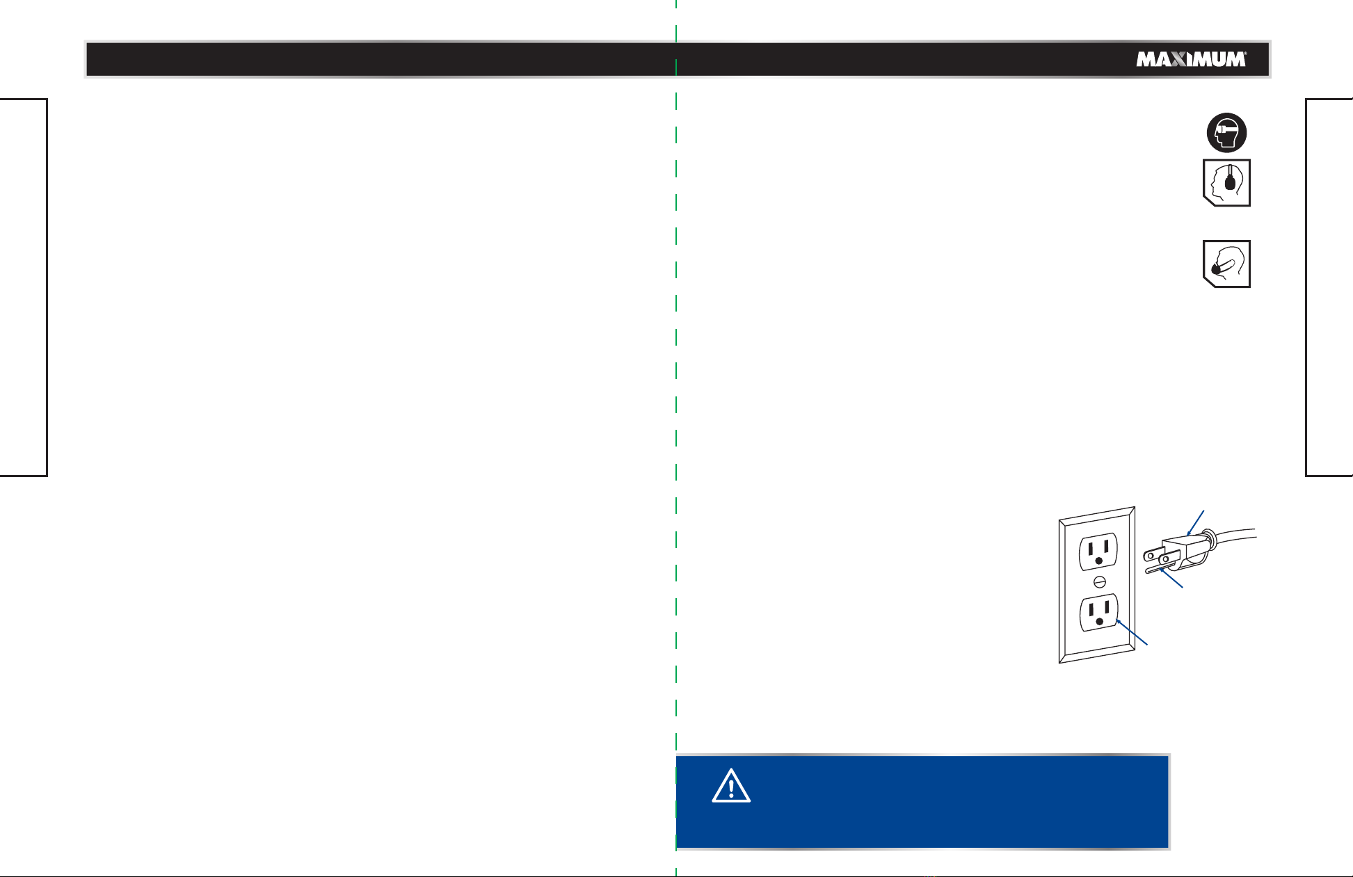
i) Wear personal protective equipment. Depending on application, use face shield,
safety goggles or safety glasses. As appropriate, wear dust mask, hearing protectors,
gloves and shop apron capable of stopping small abrasive or workpiece fragments.
The eye protection must be capable of stopping flying debris generated by various
operations. The dust mask or respirator must be capable of filtrating particles
generated by your operation. Prolonged exposure to high intensity noise may cause
hearing loss.
j) Keep bystanders a safe distance away from work area. Anyone entering the work
area must wear personal protective equipment. Fragments of workpiece or of a
broken wheel may fly away and cause injury beyond immediate area of operation.
k) Position the cord clear of the spinning accessory. If you lose control, the cord may be
cut or snagged and your hand or arm may be pulled into the spinning wheel.
l) Regularly clean the power tool’s air vents. The motor’s fan can draw the dust inside
the housing and excessive accumulation of powdered metal may cause electrical
hazards.
m) Do not operate the power tool near flammable materials. Do not operate the power
tool while placed on a combustible surface such as wood. Sparks could ignite these
materials.
g) If devices are provided for the connection of dust extraction and collection facilities,
ensure these are connected and properly used. Use of dust collection can reduce
dust-related hazards.
h) Do not let familiarity gained from frequent use of tools allow you to become
complacent and ignore tool safety principles. A careless action can cause severe
injury within a fraction of a second.
4) Power tool use and care
a) Do not force the power tool. Use the correct power tool for your application.
The correct power tool will do the job better and safer at the rate for which it was
designed.
b) Do not use the power tool if the switch does not turn it on and off. Any power tool
that cannot be controlled with the switch is dangerous and must be repaired.
c) Disconnect the plug from the power source and/or remove the BATTERY pack, if
detachable, from the power tool before making any adjustments, changing
accessories, or storing power tools. Such preventive safety measures reduce the risk
of starting the power tool accidentally.
d) Store idle power tools out of the reach of children and do not allow persons
unfamiliar with the power tool or these instructions to operate the power tool. Power
tools are dangerous in the hands of untrained users.
e) Maintain power tools and accessories. Check for misalignment or binding of moving
parts, breakage of parts and any other condition that may affect the power tool’s
operation. If damaged, have the power tool repaired before use. Many accidents are
caused by poorly maintained power tools.
f) Keep cutting tools sharp and clean. Properly maintained cutting tools with sharp
cutting edges are less likely to bind and are easier to control.
g) Use the power tool, accessories and tool bits etc. in accordance with these
instructions, taking into account the working conditions and the work to be
performed. Use of the power tool for operations different from those intended could
result in a hazardous situation.
h) Keep handles and grasping surfaces dry, clean and free from oil and grease. Slippery
handles and grasping surfaces do not allow for safe handling and control of the tool in
unexpected situations.
5) Service
a) Have your power tool serviced by a qualified repair person using only identical
replacement parts. This will ensure that the safety of the power tool is maintained.
SPECIAL INSTRUCTIONS FOR CUT-OFF MACHINE
Safety instructions for cut-off machines
1) Cut-off machine safety warnings
a) Position yourself and bystanders away from the plane of the rotating wheel. The
guard helps to protect the operator from broken wheel fragments and accidental
contact with wheel.
model no. 055-2702-8 | contact us 1-888-670-6682

USE SAFETY GOGGLES AND EAR PROTECTION:
ALWAYS WEAR EYE PROTECTION THAT CONFORMS WITH CUL
REQUIREMENTS. FLYING DEBRIS can cause permanent eye damage.
The tool is loud and the sound can cause hearing damage. Always wear
ear protection to help prevent hearing damage and loss. Failure to comply
may result in moderate injury.
USE DUST MASK:
Some dust created by sawing contains chemicals that are known to cause
cancer, birth defects or other reproductive harm. Some examples of these
chemicals come from lead-based paints, crystalline silica from bricks, cement
and other masonry products, arsenic and chromium from chemically treated
lumber. To reduce exposure to these chemicals, work in a well-ventilated area with
approved safety equipment, such as dust masks that are specially designed to filter out
microscopic particles.
ELECTRICAL SAFETY
GUIDELINES FOR USING EXTENSION CORDS:
In the event of a malfunction or breakdown, grounding provides a path of least resistance
for electric current to reduce the risk of electric shock. This tool is equipped with
an electric cord having an equipment-grounding conductor and a grounding plug. The plug
must be plugged into a matching outlet that is properly installed and grounded in
accordance with all local codes and ordinances.
Do not modify the plug provided. If it will not fit the outlet, have the proper outlet installed
by a qualified electrician.
Improper connection of the equipment-grounding
conductor can result in a risk of electric shock. The
conductor with a green outer surface, with or without
yellow stripes, is the equipment-grounding conductor.
If repair or replacement of the electric cord or plug
is necessary, do not connect the equipment-grounding
conductor to a live terminal.
Check with a qualified electrician or service technician
if the grounding instructions are not completely
understood, or if in doubt as to whether the tool is
properly grounded. Use only three wire extension
cords that have three prong grounding plugs and three pole receptacles that accept the
tool's plug, as shown in Fig. 1. Repair or replace a damaged or worn cord immediately.
2) Kickback and related warnings
Kickback is a sudden reaction to a pinched or snagged rotating wheel. Pinching or
snagging causes rapid stalling of the rotating wheel which in turn causes the uncontrolled
cutting unit to be forced upwards toward the operator.
For example, if an abrasive wheel is snagged or pinched by the workpiece, the edge of
the wheel that is entering into the pinch point can dig into the surface of the material
causing the wheel to climb out or kick out. Abrasive wheels may also break under these
conditions.
Kickback is the result of power tool misuse and/or incorrect operating procedures or
conditions and can be avoided by taking proper precautions as given below.
a) Maintain a firm grip on the power tool and position your body and arm to allow you
to resist kickback forces. The operator can control upward kickback forces, if proper
precautions are taken.
b) Do not position your body in line with the rotating wheel. If kickback occurs, it will
propel the cutting unit upwards toward the operator.
c) Do not attach a saw chain, woodcarving blade, segmented diamond wheel with a
peripheral gap greater than 10 mm or toothed saw blade. Such blades create frequent
kickback and loss of control.
d) Do not jat the wheel or apply excessive pressure. Do not attempt to make an
excessive depth of cut. Overstressing the wheel increases the loading and
susceptibility to twisting or binding of the wheel in the cut and the possibility of
kickback or wheel breakage.
e) When the wheel is binding or when interrupting a cut for any reason, switch off the
power tool and hold the cutting unit motionless until the wheel comes to a complete
stop. Never attempt to remove the wheel from the cut while the wheel is in motion
otherwise kickback may occur. Investigate and take corrective action to eliminate the
cause of wheel binding.
f) Do not restart the cutting operation in the workpiece. Let the wheel reach full speed
and carefully re-enter the cut. The wheel may bind, walk up or kickback if the power
tool is restarted in the workpiece.
g) Support any oversized workpiece to minimize the risk of wheel pinching and
kickback. Large workpieces tend to sag under their own weight. Supports must be
placed under the workpiece near the line of cut and near the edge of the workpiece
on both sides of the wheel.
Additional safety warnings
a) Always ensure the product is used on a stable and level surface.
b) Choose a worktop that is high enough so that you can operate the product in straight
standing position.
c) Ensure that there is sufficient space around the product and for the operator to move.
1) Large workpieces must not touch other objects around when handling them.
2) Ensure the motor unit can be moved in its upper position.
3) The operation handle must be accessible without touching other objects.
d) Mount the product in such way that you can stand in front of it for operation.
11
SAFETY GUIDELINES
10
SAFETY GUIDELINES
CAUTION!
• In all cases, verify that the outlet in question is properly
grounded. if you are not sure, have a licensed electrician
check the outlet.
Fig. 1
Three-prong plug
Grounding prong
Properly grounded
outlet
model no. 055-2702-8 | contact us 1-888-670-6682

GROUNDING INSTRUCTIONS:
• Make sure the extension cord is in good condition. When using an extension cord, be
sure to use one that is heavy enough to carry the current that your product will draw.
An undersized cord will cause a drop in line voltage, which will result in loss of power
and overheating. The table on the next page shows the correct size to be used
according to cord length and nameplate ampere rating. When in doubt, use the next
heavier gauge. The smaller the gauge number, the heavier the cord.
• Make sure your extension cord is properly wired and in good condition. Always
replace a damaged extension cord, or have it repaired by a qualified person before
using it. Protect your extension cords from sharp objects, excessive heat, and damp or
wet areas.
• Use a separate electrical circuit for your tools. This circuit must consist of not less than
#12 wire with a 20 A time-delayed fuse or a #14 wire with a 15 A time-delayed fuse.
Before connecting the motor to the power line, make sure the switch is in the Off position
and the electric current is rated the same as the current stamped on the motor nameplate.
Running at a lower voltage will damage the motor.
Recommended size for extension cords
SAFETY GUIDELINES
WARNING!
• Use the proper extension cord. Make sure to use an extension
cord that is heavy enough to carry the current required by
the tool. An undersized cord will cause a drop in line voltage,
resulting in loss of power and overheating of the tool.
• Use the extension cord only for intended purpose. Do not
pull the extension cord to remove it from the power socket.
• This tool must be grounded while in use in order to protect
the operator from electric shock.
AMPERAGE RATING OF THE TOOL
(120 V CIRCUIT ONLY)
MORE THAN
0
6
10
12
NOT MORE THAN
6
10
12
16
25' (7.6 m)
18
18
16
14
50' (15.2 m)
16
16
16
12
100' (30.5 m)
16
14
14
Not recommended
150' (45.7 m)
14
12
12
TOTAL LENGTH OF THE EXTENSION CORD
MINIMUM GAUGE FOR THE EXTENSION CORD (AWG)
NOTE: Recycle unwanted materials rather than disposing of them
as waste. Sort the tool and its components in specific categories and
take to the local recycling centre or dispose of them in an environmentally
safe way.
1312
model no. 055-2702-8 | contact us 1-888-670-6682
No Hands Symbol.
Failure to keep your hands away from the blade will result in serious personal
injury.
This symbol designates that this tool is listed with Canadian requirements
by CSA.
Read the instruction manual.

NOTE: bonded reinforced wheel: wheel for different applications
and of a type in accordance with ISO 603-15.
KNOW YOUR CHOP SAW
KNOW YOUR CHOP SAW
14" (35.6 CM) ABRASIVE WHEEL
A 14" (35.6 cm) abrasive wheel is included with your chop saw. It will cut materials up to
5" ( 12.7 cm) thick, depending upon the thickness or width of the material and the setting
at which the cut is being made.
MITRE GAUGE
The mitre gauge on your chop saw has been provided to support the material and provide
clamping support to the vice for holding your material securely when making all cuts. The
mitre guard provided is meant to make your chop saw more versatile. It adjusts from 0
to 45° to the left for making angled cuts. The mark pattern allows it to be moved forward
when making cuts in tall or thick stock, such as square stock or tube stock. The mark pattern
allows it to be moved back when making cuts in stock that is thin or wide, such as angle
stock.
ARBOUR WRENCH
The arbour wrench can be stored on front of the base. Use the arbour wrench when
replacing abrasive wheel or adjusting the depth stop.
CARRY HANDLE
This handle is built into the unit to move it from one location to another. Before attempting
to pick up the unit by the carry handle, always lock the power head in the down position
using the head lock button.
No.
1
2
3
4
5
6
7
8
9
10
11
12
Description
Quick-release lever
Lower wheel guard
Motor
“D” Handle
ON/OFF trigger switch
Rubber foot
Arbour wrench storage
Machine base
MItre gauge
MItre gauge lock handle
Head lock button
Depth stop
No.
13
14
15
16
17
18
19
20
21
22
23
Description
Plug cable
Carbon brush cap
Carry handle
Spindle lock button
Abrasive wheel
Vice clamp
Vice screw
Vice handle
Arbour wrench
Upper wheel guard
Spark deflector
15
14
13
11
12
10
5
2
3
4
1
20
21
22
23
16
17
18
19
6
7
9
8
1514
model no. 055-2702-8 | contact us 1-888-670-6682

WARNING!
If any parts are damaged or missing do not operate this tool
until the parts are replaced. Use of this product with damaged
or missing parts could result in serious personal injury.
• Do not attempt to modify this tool or create accessories not
recommended for use with this tool. Any such alternation
or modification is misuse and could result in a hazardous
condition leading to possible serious personal injury.
• Do not connect to power supply until assembly is complete.
Failure to comply could result in accidental starting and
possible serious personal injury.
• Risk of injury! Always pull out the mains plug (disconnect
the product from its power supply) before commencing work
on the product.
ON/OFF SWITCH
The handle contains the trigger switch. The wheel is lowered into the material by pushing
down on the handle. The abrasive wheel will return to its upright positon when the handle
is released.
LOWER WHEEL GUARD
The lower wheel guard provides protection from each side of the wheel. Contact with the
material causes the lower wheel guard to raise over the upper wheel guard as the abrasive
wheel is lowered into the material.
MOTOR
This chop saw has a strong motor with sufficient power to handle tough cutting jobs. It
also has externally accessible brushes for ease of servicing.
DEPTH STOP
The depth stop limits the wheel’s downward travel. It allows the wheel to go below the
machine base enough to maintain full cutting capacities.
QUICK-RELEASE LEVER
A quick-release lever has been provided on your chop saw. This feature allows you to release
and lock the vice clamp quickly without repetitive turning of the vice handle.
SPINDLE LOCK BUTTON
A spindle lock button has been provided for locking the spindle which keeps the wheel in
chop saw from rotating. Depress and hold the spindle lock button while installing, changing,
or removing abrasive wheel only.
UPPER WHEEL GUARD
Protects user from abrasive wheel contact on upper portion of wheel.
VICE CLAMP
A vice clamp has been provided with your chop saw. It is located on the end of the vice
screw and provides greater control by clamping the material to the fence. It also prevents
the material from creeping toward the wheel during a cutting operation.
17
ASSEMBLY
16
KNOW YOUR CHOP SAW
UNPACKING
This product has been shipped completely assembled.
• Carefully lift machine from the carton by the carry handle and machine base, and place
it on a level work surface.
PACKAGE CONTENTS
TOOLS NEEDED FOR ASSEMBLY
No. Description Qty. Illustration
Chop saw
Arbour wrench
1
2
Screwdriver 8 mm wrench
1
1
model no. 055-2702-8 | contact us 1-888-670-6682

CAUTION!
Do not start the chop saw without checking for interference
between the wheel and the machine base support. Damage
may result to the wheel if it strikes the machine base support
during operation of the machine.
WARNING!
Always disconnect your chop saw from the power source when
replacing the abrasive wheel, clamping material in the vice,
adjusting the guard, cleaning or when not in use. Disconnecting
the chop saw will prevent accidental starting that could cause
serious personal injury.
• This machine has been shipped with the machine
arm secured in the down position. To release the
machine arm, push down on the “D” handle (1) and
unlock the lock button (2) as shown in Fig. 2.
• Lift the machine arm by the handle. Hand pressure
should remain on the “D” handle to prevent sudden
rise upon release of the head lock button. Remove
the foam (3) on the machine base.
• Inspect the tool carefully to make sure no breakage
or damage occured during shipping. Do not discard
the packing material until you have carefully
inspected and satisfactorily operated the tool.
• The machine is factory set for accurate cutting.
After assembling it, check for accuracy. If shipping
has influenced the settings, refer to specific
procedures explained in this manual.
• If any parts are damaged or missing, please call
1-888-670-6682.
SELECTING THE WORK SURFACE
• It is important to place the chop saw on a solid work surface that will not shift during
operation of the chop saw. Locating the chop saw near an electrical outlet will eliminate
the need for an extension cord
19
ASSEMBLY
18
ASSEMBLY
• Hot metal sparks and sharp metal pieces will damage the work surface to some degree.
Make sure you consider this fact when selecting the work surface. A non-flammable
surface such as a metal bench will be less likely to be damaged during the cutting
operation.
SETTING THE DEPTH STOP (Fig. 3)
The maximum cut depth is controlled by adjusting
the depth stop. The depth stop limits the wheel’s
downward travel. It allows the wheel to go below the
machine base enough to maintain full cutting capacities.
The depth stop is a bolt (1) threaded into the support
on the rear of the pivot bracket, underneath the machine
arm. To adjust the depth stop use the arbour wrench
supplied to raise or lower the depth stop bolt.
The depth stop is factory set to provide maximum
cutting capacity for the 14"(35.6 cm) abrasive wheel
provided with the chop saw.
When the diameter of the wheel has been reduced due to wear, it may be necessary to
adjust the depth stop to provide maximum cutting capacity. When a new abrasive wheel
is installed, it is necessary to check the clearance of the wheel to the machine base support.
• Unplug the chop saw.
• Loosen the depth bolt (1).
• The depth stop is lowered by turning the depth stop bolt clockwise and raised by turning
the bolt counter-clockwise.
• Press down on the D-handle (2) to lower the wheel (3) then check clearance and maximum
cutting distance (distance from adjustable stationary vise where wheel enters) to front
of machine base slot.
• Adjust if necessary.
• Tighten the depth stop bolt with 8mm wrench.
Fig. 3
Fig. 2
1
1
32 2
3
NOTE!
This tool is heavy. To avoid back injury, lift with your legs, not your back, and
get help when needed.
WARNING!
A 14"(35.6 cm) wheel is the maximum wheel capacity of the chop saw. Never
use a wheel that is too thick to allow outer flange to engage with the flats on
the spindle. Larger wheel will come in contact with the wheel guards, while
thicker wheels will prevent the bolt from securing the wheel on the spindle.
Either of these situations could result in a serious accident and can cause serious
personal injury.
WARNING!
Do not release the “D” handle (1) unless the machine head is in its upper position!
Sudden jolt up of the motor unit can lead to personal injuries!
WARNING!
Make sure that the mounting surface is not warped as an uneven surface can
cause bending and inaccurate sawing!
WARNING!
Never place the chop saw near any flammable liquids or items that can be
damaged by the sparks thrown by the chop saw during cutting. The hot sparks
can ignite flammable liquids.
model no. 055-2702-8 | contact us 1-888-670-6682
1
2
4
3
Fig. 3

3
2
5
1
1
4
WARNING!
Disconnect your chop saw from the power source before
checking the arbour bolt.
WARNING!
Always disconnect your chop saw from the power source
before checking the lower wheel guard.
NOTE: The lower wheel guard should always rise and fall freely when
the machine arm is lowed and raised as outlined above. If not, clean
any cuttings out from around the guard mechanism. (3) (Fig. 5)
NOTE: Only use the arbour wrench supplied to tighten the arbour
bolt. DO NOT over tighten the arbour bolt as you could crack the
hub of the abrasive wheel.
Fig. 6
Fig. 7
CHECKING THE LOWER WHEEL GUARD (Fig. 4-5)
The lower wheel guard must be checked to ensure it
is working properly.
• Lift the lower wheel guard (1) upward approximately
3" (7.6 cm) and then release it. If the lower wheel
guard is functioning correctly, it will freely drop
down to its original position.
• Lower the machine arm and abrasive wheel assembly
until the lower edge (2) of the lower wheel guard
touches the machine base. Continue to lower the
machine arm and abrasive wheel assembly. The
lower wheel guard should freely rise as the abrasive
wheel is lowered.
21
ASSEMBLY
20
ASSEMBLY
CHECKING THE ARBOUR BOLT (Fig. 6-7)
It is important to check the arbour bolt to make sure
the abrasive wheel is fully tightened.
• Lift the machine arm fully upward as far as it wil go.
• Rotate the lower wheel guard (1) upward until you
expose the arbour bolt (2). Hold it in that position
by hand. (Fig. 6)
• Press and hold the spindle lock button (3) to the
right while rotating the abrasive wheel (4) by hand.
(Fig. 7)
• When the spindle lock button engages the arbour,
tighten the arbour bolt (2) by turning it clockwise
using the arbour wrench (5) supplied. (Fig. 7)
• When the arbour bolt is fully tightened, remove the
arbour wrench and release the spindle lock button.
• Check the lower wheel guard. Refer to the previous
section “checking the lower wheel guard”.
2
3
1
model no. 055-2702-8 | contact us 1-888-670-6682
Fig. 4
Fig. 5

WARNING!
Always make sure the workpiece is flat against the machine
base and securely held in the vice before turning the saw on.
2
1
2
1
Fig. 11
23
ASSEMBLY
22
ASSEMBLY
Fig. 8
1
1
2
4
3
Fig. 9
Fig. 10
USING THE MITRE GAUGE (Fig. 8)
The mitre gauge (1) is located at the rear of the
chop saw. It is used along with the vice clamp to
provide a clamp for holding the workpiece securely
when making cuts. It also makes the chop saw more
versatile.
The fence can be rotated to obtain cutting angles
from 0° to 45°. It also can be moved back to allow
greater cutting widths in thin stock, or forward to
allow greater cutting depths in tall or thick stock.
ADJUSTING THE CUTTING ANGLE (Fig. 9-10)
• Unplug the chop saw.
• Open the vice clamp by turning the vice handle (1)
5 or 6 turns counter-clockwise. (Fig. 9)
• Loosen mitre gauge lock handle (2) by pushing it
upward to unlock it. (Fig. 10)
• Rotate the mitre gauge (3) to the left until the
desired cutting angle lines up with the alignment
mark (4). (Fig. 10)
• Push mitre gauge lock handle down to lock it in
place.
ADJUSTING THE WIDTH OF CUT (Fig. 11)
The mitre gauge can be set using one of two slots
on the machine base.
• Unplug the chop saw.
• To increase the width of cut of the chop saw, unlock
the mitre gauge lock handle (1) by pushing it
upward.
• Move the mitre gauge (2) back.
• Lock mitre gauge lock handle by pushing it down.
3
Fig. 12
1
2
3
Fig. 13
USING THE QUICK-RELEASE LEVER AND VICE
CLAMP (Fig. 12-13)
The quick-release lever engages the vice clamp to be
used along with the mitre gauge to provide a vice
for securing the workpiece to be cut. It also allows
you to open and close the vice quickly without
repetitive turning of the vice handle.
To release: (Fig. 12)
• Unplug the chop saw.
• Release tension on the vice clamp by rotating the
vice handle (1) 1 to 2 turns counter-clockwise.
•Push down on the front of quick-release lever (2) to
release the vice screw (3).
• Pull the vice handle toward you to quickly open the
vice.
To lock: (Fig. 13)
• Unplug the chop saw.
• Push the vice handle (1) away from you to slide the
vice clamp against the workpiece.
• Rotate the quick-release lever (2) backwards to
engage the vice screw (3).
• Rotate the vice handle (1) clockwise to tighten the
vice clamp against the workpiece.
NOTE: Always make a test cut on a scrap workpiece to verify the
mitre angle setting.
model no. 055-2702-8 | contact us 1-888-670-6682
Fig. 10
Fig. 8
Fig. 11

WARNING!
For safety reasons, the operator must read the sections of this Owner’s Manual
entitled “SAFETY GUIDELINES” and “ELECTRICAL SAFETY” before using this chop saw.
Verify the following every time the chop saw is used:
• Cord is not damaged.
• Abrasive wheel is correct for the type of material being cut.
• Abrasive wheel is in good condition and securely tightened onto the arbour.
• Safety glasses, dust mask and hearing protection are being worn.
• Guard is in good working order.
• No flammable liquids are in the vicinity.
Failure to adhere to these safety rules can greatly increase the chances of serious injury.
WARNING!
Do not allow familiarity with tools to make you careless. Remember that a careless
fraction of a second is sufficient to inflict severe injury.
WARNING!
Always wear safety goggles or safety glasses when operating tools. Failure to do
so could result in objects being thrown into your eyes resulting in possible serious injury.
WARNING!
Do not use any attachments or accessories not recommended by the manufacturer
of this tool. The use of attachments or accessories not recommended can result in serious
personal injury.
WARNING!
Do not attempt to cut wood or masonry with this chop saw. Never cut magnesium
or magnesium alloy with this machine. Failure to comply could result in serious personal
injury.
WARNING!
Never install any wood cutting blade on this machine. The chop saw is properly
guarded only for cutting metal with an abrasive wheel. Failure to comply could result in
serious personal injury.
WARNING!
Always use the vice clamp on the chop saw to prevent accidents that could result
in possible serious personal injury.
WARNING!
Large, circular, or irregularly-shaped material may require additional means
of clamping to be secured in place adequately for cutting (for example, use blocks to hold
material securely). Failure to comply could result in serious personal injury.
WARNING!
Always make sure the abrasvie wheel is NOT touching the
workpiece when the switch is being turned on. Let the motor
come to full speed before beginning to cut.
1
2
Fig. 14
2524
APPLICATIONS
You may use this tool for the purposes listed below:
• Cutting all types of metals such as steel framing studs.
• Cutting hard metal iron stock such as square bar stock and angle iron.
• Cutting metal tube and pipe stock.
POWER SUPPLY
Before operating the chop saw, check the power supply and make sure it meets
the requirements listed on the tool’s data plate. A substantial voltage drop will cause a
loss of power and machine overheating.
Common causes of power loss and machine overheating are insufficient extension cord
size and multiple tools operating from the same power source.
ON/OFF SWITCH (Fig. 14)
• To turn the chop saw on, depress the ON/OFF
switch (1) located in the “D” handle (2) portion of
the machine arm.
• To turn it off, release the ON/OFF switch.
OPERATION
OPERATION
model no. 055-2702-8 | contact us 1-888-670-6682
Fig. 14

WARNING!
Many sparks will be generated as soon as the abrasive wheel touches the
material.
• When the cut is complete, release the ON/OFF switch and allow the wheel to stop rotating
before raising the wheel out of material.
CUTTING WITH THE CHOP SAW
A cut-off is made by cutting across the width of the material. A straight cross cut is made
with the mitre gauge set at the zero degree position. Angled cut-offs are made with the
mitre gauge set at some angle other than zero.
• Lift the “D” handle fully upward as far as it will go.
• Release mitre gauge lock handle securing the mitre gauge.
• Rotate the mitre gauge to the desired angle.
• Lock mitre gauge lock handle securing the mitre gauge.
WARNING!
To avoid serious personal injury, always lock mitre gauge lock handle securely
before making a cut. Failure to do so could result in movement of the material
while making a cut.
• Place the material flat on the machine base with one surface securely against the mitre
gauge.
• Align cutting line on the material with the edge of the abrasive wheel.
• Push in the vice handle to set the vice clamp against the material. Turn the vice handle
1 to 2 turns clockwise to securely clamp the material to the mitre gauge.
• Firmly secure the material to be cut using the machine’s vice (mitre gauge and vice
clamp).
• When cutting long pieces, support the opposite end of the material with a roller stand
or with a work surface level with the machine base.
WARNING!
Never perform any cutting operation freehand (without placing material in the
vice). Material will get hot during cutting operation. Keep hands off of metal being cut to
avoid serious personal injury.
• Make sure you are wearing your safety goggles, dust mark and hearing protection.
• Before turning on machine, perform a dry run of the cutting operation just to make sure
that no problems will occur when the cut is made.
• Start the machine by grasping the handle and fully squeezing the ON/OFF switch. Allow
several seconds for the wheel to build up to full speed before letting it come into contact
with material to be cut.
WARNING!
The abrasive wheel MUST NOT be touching the material when the motor switch
is turned on.
• Once it reaches full speed slowly lower the “D” handle until the abrasive wheel comes
in contact with the material being cut. Continue to use steady and even pressure to
obtain a uniform cut through the material. Never force the wheel into the material being
cut.
WARNING!
Do not touch the cut material until it cools or you can
be burned. Failure to heed this warning could result in
serious personal injury.
27
OPERATION
26
OPERATION
model no. 055-2702-8 | contact us 1-888-670-6682

3
2
5
1
1
4
Fig. 14
Fig. 15
WARNING!
When servicing, use only indentical replacement parts. The use of any other part
may create a hazard or cause product damage.
WARNING!
Always wear safety goggles during power tool operation or when blowing dust.
If operation is dusty, also wear a dust mask.
Fig. 16
LUBRICATION
All of the bearings in this tool are lubricated with a sufficient amount of high-grade
lubricant for the life of the unit under normal operating conditions. Therefore, no further
lubrication is required.
ABRASIVE WHEEL REPLACEMENT (Fig. 14-16)
Abrasive wheel must be replaced when it has
become damaged in any way or has worn down to
a diameter of less than 10" (25 cm).
• Unplug the chop saw.
• Lift the machine arm fully upward as far as it wil go.
• Rotate the lower wheel guard (1) upward until you
expose the arbour bolt (2). Hold it in that position
by hand.
• Press and hold the spindle lock button (3) to the
right while rotating the abrasive wheel (4) by hand.
(Fig. 14)
• When the spindle lock button engages the arbour,
loosen the arbour bolt (2) by turning it counter-
clockwise using the arbour wrench (5) supplied.
(Fig. 15)
• Remove the arbour bolt (2), small flange (6), outer
flange (7), abrasive wheel (8) and inner flange (9)
from the arbour (10). (Fig. 16)
• Use a clean dry brush or cloth to carefully remove
all cuttings from the arbour and motor housing.
• Clean the inner flange then slide it onto arbour.
• Place a new abrasive wheel against the inner flange
over arbour and make sure recessed side of the
GENERAL
Avoid using solvents when cleaning plastic parts. Most plastics are susceptible to damage
from various types of commercial solvents and may be damaged by their use. Use a clean
cloth to remove dirt, carbon dust, etc.
CAUTION!
Do not at any time let brake fluids, gasoline, petroleum-based products,
penetrating oils, etc., come in contact with plastic parts. They contain chemicals that can
damage, weaken or destroy plastic.
CAUTION!
Reinstall the inner flange, new abrasive wheel, outer flange, small flange and
arbour bolt in the same order in which they were removed.
NOTE!
Make sure the recessed side (large surfaces) of the outer flange and small flange
are facing the abrasive wheel.
NOTE!
Arbour bolt has right-hand threads. Turn arbour bolt clockwise to tighten.
NOTE!
Make sure the flats of the inner flange, outer flange and small flange holes slide
over the matching flats of the arbour.
WARNING!
If the inner flange has been removed, you MUST replace it before placing the
abrasive wheel. Failure to do so could cause an accident since abrasive wheel will not
tighten properly.
WARNING!
Do not overtighten arbour bolt. Overtightening can cause the new abrasive wheel
to crack, resulting in premature failure and possible serious personal injury.
2
7
8
10
6
9
29
MAINTENANCE
28
inner flange is against the abrasive wheel.
• Clean the outer flange and small flange then slide
the outer flange and small flange onto arbour until
it is flush.
• Place recessed side of outer flange against abrasive
wheel and recessed side of small flange against
outer flange, then insert the abour bolt into
threaded end of the arbour.
• Start threads and turn arbour bolt clockwise to tighten snugly.
• Press and hold the spindle lock button to the right. When the spindle lock button engages
the arbour, tighten the arbour bolt by turning it clockwise using the arbour wrench supplied.
• When the arbour bolt is fully tightened, remove the arbour wrench, and release the spindle
lock button.
• Carefully rotate the abrasive by hand to make sure it is firmly tightened, that it is not
damaged and that it does not wobble.
• Lower the lower wheel guard.
model no. 055-2702-8 | contact us 1-888-670-6682
MAINTENANCE

2
1
2
1
1
WARNING!
Reset the depth stop by referring to the section “SETTING THE DEPTH STOP”.
The new blade will be larger and will damage the work surface if the depth stop in not
readjusted.
NOTE:
If the abrasive wheel wobbles or vibrates, turn the switch off immediately. Recheck
to make sure the abrasive wheel is installed correctly and that the abrasive wheel is not
damaged.
CARBON BRUSH REPLACEMENT (Fig. 17)
The chop saw has externally accessible carbon brush
assemblies that should be periodically checked for
wear.
Proceed as follows when replacement is required:
• Unplug the chop saw.
• Remove the carbon brush cap (1) with a screwdriver
(not supplied). Carbon brush assembly (4) is spring-
loaded and will pop out when you remove the
carbon brush cap.
• Remove the carbon brush assembly (2).
• Check for wear. Replace both carbon brushes when
either has less than 1/4" (6 mm) length of carbon
brush remaining. Do not replace one side without
replacing the other.
• Reassemble using new carbon brush assemblies.
Make sure curvature of carbon brush matches
curvature of motor and carbon brush moves freely
in brush tube.
• Make sure carbon brush cap is oriented correctly
(straight) and replace.
• Tighten carbon brush cap securely. Do not
overtighten.
• With depth stop properly set, turn the switch on.
Fig. 18
Fig. 19
STORAGE OF THE ARBOUR WRENCH (Fig. 18)
Store the arbour wrench (1) on the front of the chop
saw when not in use, as shown in Fig. 18.
LOCKING THE MACHINE ARM FOR CARRYING (Fig. 19)
To safely carry the chop saw, it is important to lock
the machine arm and carry the tool with the
appropriate carry handle.
• Lower the machine arm (1) as far as it will go.
• Push inward on the head lock button (2) until it
engages the hole in the machine arm.
• Release the machine arm. It will be locked in the
DOWN position if the head lock button is properly
engaged.
• Lift the chop saw using the carry handle (3).
31
MAINTENANCE
30
MAINTENANCE
Fig. 17
model no. 055-2702-8 | contact us 1-888-670-6682
1
3
2

33
TROUBLESHOOTING
32
TROUBLESHOOTING
PROBLEM Possible Causes Solution
Machine does not
start.
• Power cord not plugged in.
• Power cord is damaged.
• Circuit breaker is tripped.
• Circuit fuse is blown.
• Switch is damaged or
burned out.
• Plug in cord.
• Have the cord replaced
at your nearest
authorized service centre.
• Reset circuit breaker.
• Replace circuit fuse.
• Have the switch replaced
at your nearest authorized
service centre and request
a voltage check from the
power company.
Motor does not
reach full speed or
power.
• Voltage from power
source is low.
• Circuit is overloaded.
• Motor burned out.
• Fuses or circuit breakers
are wrong size.
• Extension cord is too long.
• Switch is defective.
• Request a voltage check
from the power company.
• Test on a different circuit
or without anything else
on circuit.
• Have tool serviced and
request a voltage check
from the power company.
• Have an electrician replace
with a 15 A fuse or circuit
breaker.
• Use a shorter extension
cord.
• Have the switch replaced
at your nearest authorized
service centre.
Motor stalls, blows
fuses, or trips circuit
breakers.
• Switch is defective.
• Voltage from source is low.
• Fuses or circuit breakers
are wrong size or
defective.
• Have the switch replaced
at your nearest authorized
service centre.
• Request a voltage check
from the power company.
• Have an electrician replace
with a 15 A fuse or circuit
breaker.
Motor overheats. • Motor is overloaded.
• Wheel is being fed into
work too fast.
• Request a voltage check
from the power company.
• Feed wheel into work
slower.
PROBLEM Possible Causes Solution
Machine is noisy
when running.
• Motor needs attention. • Have the motor checked
at your nearest authorized
service centre.
Wheel hits table. • Wheel not properly
installed.
• Depth stop setting
incorrect.
• See Abrasive Wheel
Replacement section.
• Adjust the depth stop.
See Setting the Depth
Stop section.
Wheel does not cut
through material.
• Depth stop setting
incorrect.
• Wheel worn too much.
• Incorrect cutting
operation.
• Adjust the depth stop.
See Setting the Depth
Stop section.
• Replace with a new 14"
(35.6 cm) abrasive wheel.
• See Cutting with the
Chop Saw section.
Machine vibrates or
shakes excessively.
• Wheel is out-of-round.
• Wheel is chipped.
• Wheel is loose.
• Machine is not secure.
• Work surface is uneven.
• Replace wheel.
• Replace wheel.
• Tighten wheel bolt on
arbour.
• Check and tighten all
hardware.
• Relocate and secure on a
flat surface.
TROUBLESHOOTING
model no. 055-2702-8 | contact us 1-888-670-6682

4
51
45
5
6
44
41
11
14
15
16
17
19
9
22
23
27
33
34
20
21
57
61
54
56
54
55
57
60
20
62
58
39
36
53
52
3
2
1
37
59
36 26
50
49
39
35
48
13 43
47
7
42
40
16
63
28
30 32
31
29
26
8
12
9
18
105
46
No.
1
2
3
4
5
6
7
8
9
10
11
12
13
14
15
16
17
18
19
20
21
22
23
26
27
28
29
30
31
32
Qty.
1
1
1
1
2
1
1
1
5
1
1
1
1
1
1
2
1
1
4
3
2
6
1
1
1
1
1
1
1
1
Description
Screw M5 x 50
Handle
Motor assembly
Mitre gauge lock handle
Spring pin (A)
Shaft
Mitre gauge
Lock block
Big washer 8
Connection shaft
Vice handle
Flexible pin Ø6 x 40
Brace
Splint
Big washer 10
Lock nut M10
Arbour wrench
Protective coil
Rubber foot
Flat washer 8
Spring washer 8
Screw M8 x 20
Lower pressure plate
Lock nut M8
Point shaft
Base assembly
Flexible pin Ø5 x 12
Spark deflector
Flat washer 6
Spring washer 6
No.
33
34
35
36
37
39
40
41
42
43
44
45
46
47
48
49
50
51
52
53
54
55
56
57
58
59
60
61
62
63
Qty.
1
1
1
3
2
2
1
1
1
1
1
1
1
1
1
1
1
1
1
1
2
1
1
2
1
1
1
1
1
1
Description
Screw M6 x 16
Connection shaft (B)
Screw M6 x 12
Spring washer 5
Flat washer 5
Screw M5 x 16
Limited pin
Positioning base
Ring
Screw M10
Hex nut M6
Sleeve
Hex bolt M8 x 45
Torsion spring
Pressure pad
Flat washer Ø12 x Ø30 x 2
Liner
Lock shaft
Screw M5 x 65
Upper wheel guard
Wheel flange
Washer
Wheel
Guard washer
Small flange
Lock nut M5
Hex bolt M10 x 30
Lower wheel guard
Screw M5 x 10
Screw M8 x 18
35
PARTS LIST
34
EXPLODED VIEW
PARTS LIST
model no. 055-2702-8 | contact us 1-888-670-6682

37
WARRANTY
36
WARRANTY
model no. 055-2702-8 | contact us 1-888-670-6682
5-Year Limited Warranty
This MAXIMUM product is guaranteed for a period of 5
years from the date of original retail purchase against
defects in workmanship and materials only and is
subject to the following components:
a) Component A: The carrying case is guaranteed for a
period of 1-year from the date of original retail
purchase against defects in workmanship and materials.
b) Component B: Accessories, including drill bits and
saw blades, do not carry a warranty.
Subject to the conditions and limitations described
below, this product, if returned to us with proof of
purchase within the stated warranty period and if
covered under this warranty, will be repaired or replaced
(with the same model, or one of equal value or specification), at
the sole discretion of the Maximum Canada authorised repair centre
(“Service Provider”). We will bear the cost of any repair or replacement and any costs of
labour relating thereto.
These warranties are subject to the following conditions and limitations:*
a) a bill of sale verifying the purchase and purchase date must be provided;
b) defects in workmanship and material to be assessed and determined by the Service
Provider;
c) this warranty will not apply to any product or part thereof which is worn or broken or
which has become inoperative due to abuse, misuse, accidental damage, neglect or
lack of proper installation, operation or maintenance (as outlined in the applicable
owner’s manual or operating instructions);
d) this warranty does not apply to normal wear and tear or to expendable parts or
accessories (including drill bits and saw blades) that may be supplied with the
product that by their nature have a limited life span and are expected to become
inoperative or unusable after a reasonable period of use;
e) this warranty will not apply to routine maintenance and consumable items such as,
but not limited to, fuel, lubricants, vacuum bags, blades, belts, sandpaper, bits, fluids,
rubber o-rings, tune-ups or adjustments;
f) this warranty excludes the following components that may accompany your product:
(1) The carrying case, which is only for a period of 1-year from the date of original
retail purchase against defects in workmanship and materials.
(2) Accessories, including drill bits and saw blades, which do not carry a warranty of
any kind.
g) this warranty will not apply where damage is caused by repairs made or attempted
by others (i.e. persons not authorized by the manufacturer), and any such
unauthorized repairs or attempted repairs shall void this warranty in its entirety;
h) this warranty will not apply to any parts other than original parts, except to the
extent that the retailer or manufacturer or persons authorized by either of them have
repaired or replaced them;
i) this warranty will not apply to any product that was sold to the original purchaser as
a reconditioned or refurbished product (unless otherwise specified in writing);
j) this warranty will not apply to any product or part thereof if any part from another
manufacturer is installed therein or any repairs or alterations have been made or
attempted by unauthorized persons;
k) this warranty will not apply to normal deterioration of the exterior finish, such as, but
not limited to, scratches, dents, paint chips, or to any corrosion or discolouring by
heat, abrasive and chemical cleaners; and
l) this warranty will not apply to component parts sold by and identified as the product
of another company, which shall be covered under that product manufacturer’s
warranty, if any;
m) any products replaced by the retailer in attempt to fulfill warranty obligations is
subject to the original product warranty conditions and related time period as
initiated by the original date of purchase; if product is purchased in Quebec, the
warranty term will be extended for a period equal to the time during which the
Quebec retailer possesses the product in attempt to fulfill warranty obligations;
replaced product will not default to new product warranty conditions; and
n) the retailer and manufacturer’s sole obligation and the purchaser’s sole remedy under
this warranty shall be as set out herein. The warranties contained herein are not
transferable and are given only to the purchaser. FURTHER, THE WARRANTIES SET
OUT HEREIN ARE IN LIEU OF ALL OTHER WARRANTIES OR CONDITIONS, WHETHER
EXPRESS, IMPLIED OR STATUTORY (INCLUDING SUCH AS ARISE UNDER THE SALE
OF GOODS ACT OR THE INTERNATIONAL SALE OF GOODS ACT), ARISING OUT OF
A COURSE OF DEALING OR USAGE OF TRADE OR OTHERWISE, INCLUDING,
SUBJECT TO APPLICABLE LAW, ANY IMPLIED WARRANTIES OR CONDITIONS OF
MERCHANTABILITY, MERCHANTABLE QUALITY, FITNESS OR ADEQUACY FOR A
PARTICULAR PURPOSE OR USE, AND ALL OTHER SUCH WARRANTIES ARE
EXPRESSLY DISCLAIMED BY THE RETAILER AND MANUFACTURER.
Additional Limitations
This warranty applies only to the original purchaser and may not be transferred.
This warranty applies for a period of 5 years from the date of original retail purchase, as
indicated on the bill of sale.
Neither the retailer, Maximum Canada, nor the manufacturer shall be liable for any other
expense, loss or damage, including, without limitation, any indirect, incidental,
consequential or exemplary damages arising in connection with the sale, use or inability
to use this product.
Under no circumstances shall the retailer, Maximum Canada, or manufacturer be liable to
the purchaser for any claim for (a) indirect, special, punitive, incidental, exemplary, or
consequential damages, (b) compensation for loss of profits, anticipated revenue, savings
or goodwill, or other economic loss of the purchaser, (c) exemplary, aggravated or
punitive damages howsoever incurred, (d) contribution or set-off in respect of any claims
against the purchaser, (e) any damages whatsoever relating to third party products or
services or the purchaser’s materials, or (f) any damages whatsoever relating to
DAYS
JOURS
90
DE SATISFACTION
GARANTIE
SATISFACTION
GUARANTEE
YEAR
AN
1
DE GARANTIE
SUR RÉPARATIONS
REPAIR
WARRANTY
YEAR
ANS
5
DE GARANTIE
LIMITÉE
LIMITED
WARRANTY

model no. 055-2702-8 | contact us 1-888-670-6682
38
WARRANTY
interruption, delays, errors or omissions; in each case under any theory of law or equity,
arising out of or in any way related to this warranty, even if advised of the possibility
thereof. Notwithstanding any provision herein or entitlement of the purchaser at law, in
equity or otherwise, in no event shall the liability of the retailer or manufacturer under
this warranty, whether in contract, tort, product liability or otherwise, exceed, in the
aggregate, the amount paid by the purchaser to the retailer for the product to which this
warranty applies.
*Notice to Consumer
This warranty gives you specific legal rights, and you may have other rights, which may
vary from province to province. The provisions contained in this warranty are not
intended to limit, modify, take away from, disclaim or exclude any statutory warranties
set forth in any applicable provincial or federal legislation.
In addition to the 5-Year Limited Warranty, this MAXIMUM product is covered by our:
1-Year Repair Warranty
Maximum Canada will maintain this product and replace critical parts which have worn
beyond reasonable use through normal use of such product, any time during the first
year after purchase.
The following are excluded from this 1-Year Repair Warranty:
a) Missing or damaged parts or components that are a result of abuse or misuse;
b) Any wear and tear to non-critical parts or accessories that do not affect the core
function of the product.
90-Day Satisfaction Guarantee
If you are not completely satisfied with the performance of your MAXIMUM product for
any reason, you can return it within 90 days from the date of purchase with proof of
purchase for exchange or a full refund.
Made in China
Imported by MAXIMUM Canada Toronto, Canada M4S 2B8
Table of contents
Other Maximum Saw manuals

Maximum
Maximum MS10300 User manual

Maximum
Maximum 055-6706-6 User manual

Maximum
Maximum 055-6767-0 User manual

Maximum
Maximum 055-6766-2 User manual

Maximum
Maximum 054-8382-4 User manual

Maximum
Maximum 5110 User manual

Maximum
Maximum 055-9033-8 User manual

Maximum
Maximum 054-8286-4 User manual

Maximum
Maximum 054-8364-8 User manual

Maximum
Maximum MS20300 User manual