Brobo FA 3000K User manual

Precision Drilling Machines Tapping Machines Multi Head Drills Tool Grinders
Tool Post Grinders Machine Vices Special Production Equipment
Accessories Riveting Machines Pedestal Grinders Metal Cutting Saws Linishers
YOUR BROBO WALDOWN DISTRIBUTOR IS:
PRODUCT AND MAINTENANCE MANUAL
FA 3000K FULLY AUTOMATIC SAW
MODEL: S350D FERROUS SAW
BROBO WALDOWN (AUST) PTY. LTD.
A.C.N. 098 264 316
A.B.N. 42 098 264 316
8 Fowler Rd, Dandenong, 3175
PO BOX 4274 Dandenong Sth, 3164
Victoria, AUSTRALIA.
Tel: 61 3 9792 9944 Email: info@brobo.com.au
Fax: 61 3 9791 9955 Website: www.brobo.com.au
Quality
Endorsed
Company
ISO 9001 Lic. 10292
Standards Australia
Quality System


FA 3000K PRODUCT OPERATION AND MAINTENANCE MANUAL
Table of Contents
Section Page
1.
Technical Specification
1
2.
Installation of the Machine
3
2.1
Unpacking and Handling the Machine
3
2.2
Minimum Requirements
4
3.
Main Functions and Operation
5
3.1
FA 3000K Calibration
7
3.2
FA 3000K Fully Automatic Operation
8
3.3
Semi-Automatic and Length Stop Mode
10
3.4
Job Lists
11
4.
Unit Maintenance and Consumables
12
4.1
Role of the Operator
12
4.2
General Maintenance of Functioning Components
12
4.3
Maintenance Requirements
14
5.
Layouts, Assembly and Spare Parts
15
6.
Safety and Accident Prevention
30
6.1
Operation of the Machine
30
6.2
Safety Notes
31
6.3
Advice for the Operator
34
6.4
Reference Standards
35
7.
Troubleshooting Guide
37
7.1
General Troubleshooting
37
Appendix A
Risk / Hazard Assessment
38

1. TECHNICAL SPECIFICATIONS
Cutting Unit Specifications
Cutting Unit Brobo S350D Ferrous Unit
Main Motor Power 2.2 KW (415 V, 3-phase)
Main Motor Torque 7.5 Nm
Main Motor RPM 2800 RPM (at 50 Hz)
Main Drive Ratio 1:33 (Reduction)
Blade RPM (Speed) 30 to 80 RPM (33 to 88 m/min)
Sound Level < 85 dB(A)
Blade Specification
Standard Blade HSS AISI M-Z High Speed Steel (62-64 HRC, Hollow Ground)
Size ∅350 mm, 180 teeth, 2.5 mm thickness
Mount ∅40 mm bore, 2 × ∅8 mm holes, ∅55 mm PCD (Brobo mount)
Blade Selection Chart
(HSS Ø350 mm Blade Only)
Material
Outer Diamater
(mm)
Wall
Thickness
(mm)
Recommended
Number of Teeth
HOLLOW
SECTIONS
20
1
350
2
280
3
220
40
1
260
2
250
3
180
4
160
50
1
350
2
280
3
200
4
180
5
160
80
1
320
2
220
3
200
4
180
5
160
100
1
300
2
200
3
180
4
140
5
120
120
1
300
2
200
3
180
4
160
5
120
SOLID
SECTIONS
10
-
280
20
200
30
160
40
140
50
100
60
80
Table 1.1 – Blade Selection Chart (Ø350 mm HSS Blade)
NOTE – This chart is issued as a GUIDE ONLY and appropriate blade selection is wholly the responsibility of the
Operator. Brobo Waldown Pty Ltd does not accept any responsibility for unsatisfactory cutting performance and/or
machine or blade breakage as a result of blade selection.
20 August 2016 Technical Specifications 1

Vice Clamps
Type Manual adjusting pneumatic clamp
Air Requirements Dry, filtered, lubricated air supply
Working Air Pressure 600 KPa (6 bar, 87 PSI)
Maximum Air Pressure 1000 KPa (10 bar, 145 PSI)
Clamping Range 0 to 135 mm (145 mm without wear plates)
Clamping Force 1620 N/bar (9720 N at 6 bar working pressure)
Cutting Range
Profile Angle Max Cutting Capacity
(mm)
RHS
Bar 45° 115
90° 110
RHS
Square 45° 100 × 100
90° 85 × 85
RHS
Rectangular 45° 85 × 135
90° 75 × 95
Solid
Sections 90° 60
Table 1.2 – Saw Cutting Range
NOTE: Values based on a full sized new blade. Capacity is reduced with a worn or resharpened blade.
Saw Feed Specifications
Feed Rate (max) 32 mm/s
Feed Stroke (max) 125 mm
Material Feed Specifications
Feed Rate (max) 500 mm/s
Feed Stroke (max) 2590 mm
Overall Dimensions
Dimensions 3880 × 1,800 × 560 mm
Weight 315 kg
Table Working Height 968mm
20 August 2016 Technical Specifications 2

2. INSTALLATION OF THE MACHINE
2.1 Unpacking and Handling the Machine
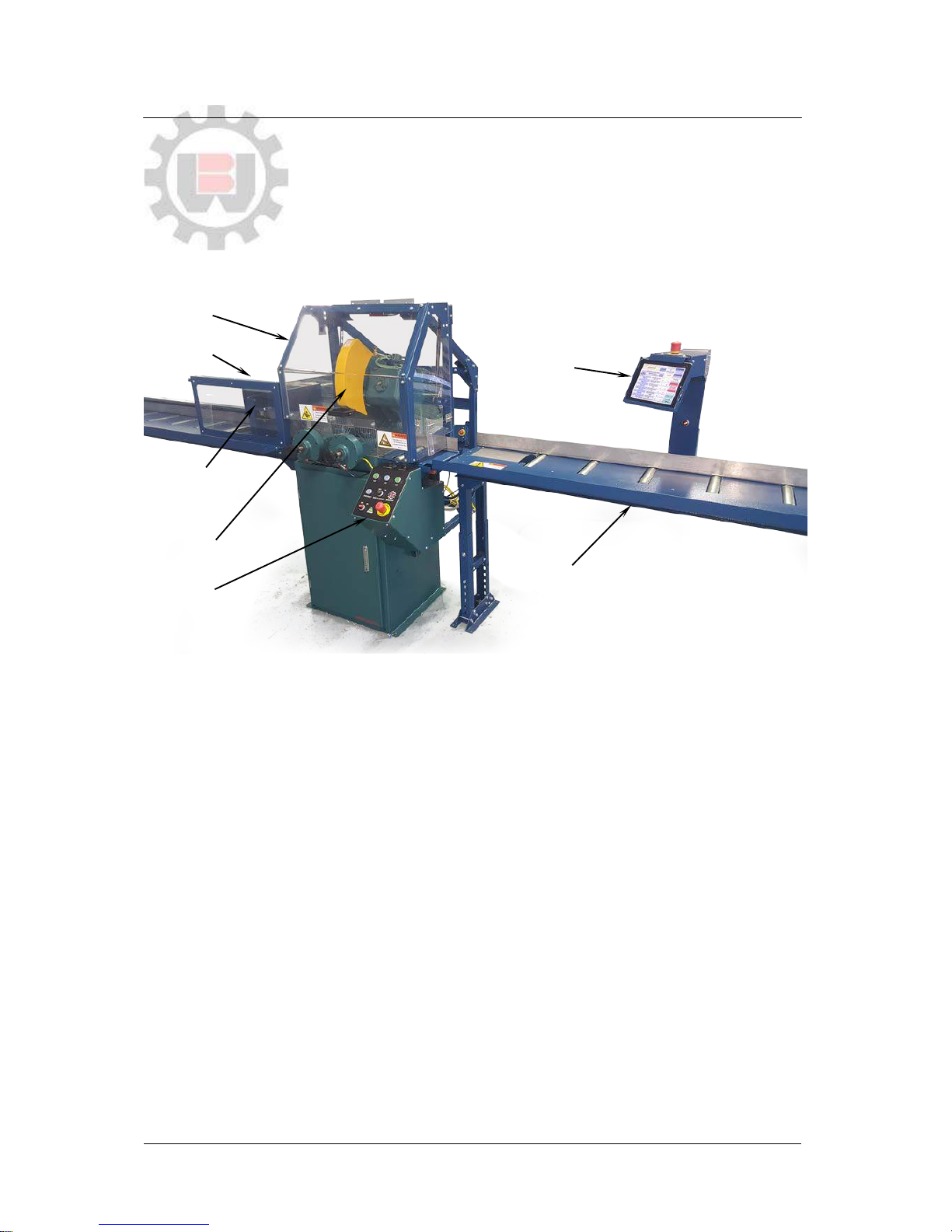
FA 3000K consists of the following major components (Figure 2.1):
Brobo S350D cold saw with automatic actuation
F3000 automatic material feeder
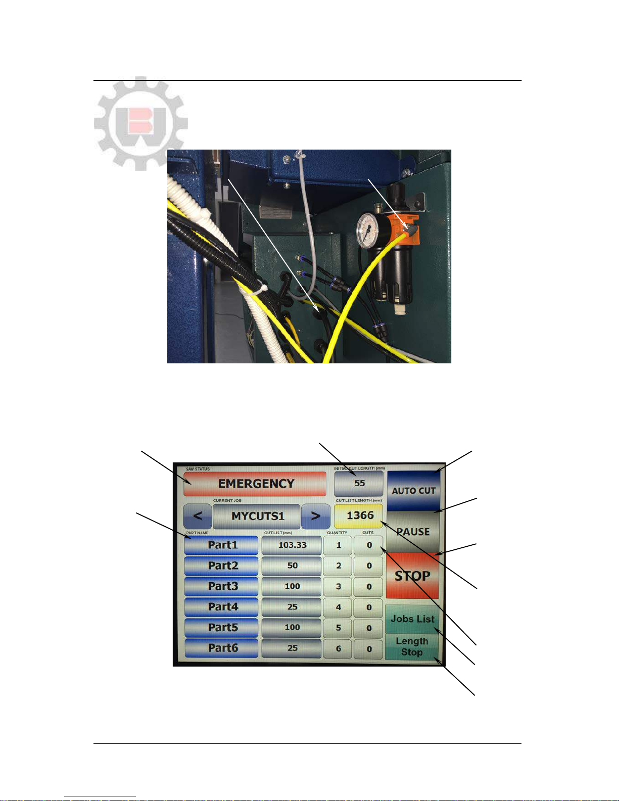
Electrical control box with 10 inch HMI touch screen
Figure 2.1 – FA 3000K Major Components
FA 3000K will arrive at your workshop in three packages:
FA Cold saw unit with electrical box.
Material feeder unit.
Spare table with the control tablet.
Cold saw unit is the heaviest of the components, hence needs to be placed in position first with the rest of the
machine to be built around it. When selecting suitable space keep in mind the space requirements of the feeder
unit which is 3+ m long.
When happy with unit position, unpack the material feeder and proceed first to attach the feeder legs to the main
body (using four M8 bolts), and then to attach the material feeder itself to the cold saw unit (two M10 bolts). Refer
to Section 5 for machine assembly drawings.
Place the electrical box as illustrated in Figure 2.1, leaving the Operator in optimum position, accessible to
controls and the main cutting area, but out of the way of the machine cutting and feeding zone.
When determining location for the machine, ensure that floor is as level as possible and that the requirements
from Section 2 (below) and safety precautions in Section 6 are adequately met. Additionally for best performance
ensure that the feeder working table is leveled, adjusting the two standing feet if necessary.
When sourcing the power supply cable, check that they are within the acceptable standards (Section 6). Install the
power cable as per electrical schematics in Figures 5.5 and 5.6 (Section 5). The installation of the Earthing
system must comply with the IEC Standards Part 195: Earthing and Protection Against Electric Shocks 1998.
Insufficient lighting during the unit operation would constitute a safety hazard according to the ISO 8995 – 2002
‘Lighting of Indoor Workplaces’. For this reason, the user must provide adequate lighting in the working area
(500 LUX), while also preventing dazzling illumination sources.
Material
Feeder
Unit
Electrical
Box
FA
Cold Saw
Unit
Main Saw
Guard
10 inch
Touch Screen
Tablet
Feeder
Guard
Steel Roller
Table
20 August 2016 Installation of the Machine 3

2.2 Minimum Requirements
For the machine to operate correctly, the place where the saw is to be positioned must be in the vicinity of and
satisfy the following conditions:
1) 5-wire 415 VAC 3-phase with neutral wire and ground
2) Lighting more than 500 LUX
Note that neutral wire MUST be connected to the system.Without neutral wire, sensitive electronic equipment
can be damaged.
20 August 2016 Installation of the Machine 4

3. MAIN FUNCTIONS AND OPERATION
Upon placing the machine in position, connect the power cable as per Section 5 electrical schematics and plug it
into the power socket (note the machine can only run on 5-wire 440V 3-phase power, not on 4-wire). Connect the
machine to the air-compressor system at the main air supply connections (Figure 3.1).
Machine is now ready to be turned on.
Figure 3.1 – Main Air-Supply Connections
Figure 3.2 illustrates FA 3000K control panel and the external control buttons. Machine operation is controlled
two-fold by external push buttons shown in the Figure 3.2 (Emergency Stop, Start button, Reset button and the
Main Power switch), and the touch-screen buttons which are displayed electronically on the Control Panel.
Figure 3.2– Main Control Screen
COMPRESSED
AIR SUPPLY
3-PHASE POWER
SUPPLY CABLE
Machine Status
Panel and Re-
Calibrate Button
Initial Cut Length
(Not Applicable)
Start Auto
Cutting
Pause Auto
Cutting (Feeder
Operation Only)
Stop Auto
Cutting (Feeder
and Saw)
Parts Cut List:
Part Name,
Length, Qty
Requested
Cuts
Counter
Calculated
Total Stock
Length
Required for
the Cut List
Entered
Go To Job
List Screen
Go To
Length Stop
Screen
20 August 2016 Main Functions and Operation 5

Figure 3.2– FA 3000K Touch Panel and Control Buttons
To switch the machine on, turn the on / off power switch to the ON position. You also may need to turn on the
switch on the feeder box, and turn on the tablet by scrolling the tablet on / off button. This will light up the control
panel screen as well as all on / off buttons if machine is powered. Once the Control Panel powers up, the machine
is ready for operation.
There are two ways to stop the machine:
Emergency stop executed by pressing any mushroom button.
Controlled stop by pressing Home / Reset button on the control box, Stop button on the control panel,
opening of the guard, or loss of air pressure.
Pressing ANY emergency stop on the machine will turn off all operating machine units in an emergency. A
machine calibration is required after an emergency stop. Activating controlled stop will immediately stop the
operation, release clamps, stop saw motor and retract to home position. No calibration is required after a
controlled stop.
Pressing emergency stop will turn off the power lights which indicate the machine is not powered. Always refer to
power lights for the correct power status of the machine.
On/Off Switch with
Power Light
Home/Reset
Dual Start
(Semi-Auto Mode Only)
Spindle
RPM
Saw Feed
Rate
Dual Start
(Semi-Auto Mode Only)
Set Stroke
End Cut Detect
Emergency
20 August 2016 Main Functions and Operation 6

3.1 FA 3000K Calibration
Upon powering up, the first screen displayed is the calibration shown in Figure 3.3:
Figure 3.3 – Startup Screen
On power up and after every emergency stop, the machine requires calibration.
Before pressing calibrate button ALWAYS ensure that:
The feeder travelling zone is clear of obstacles.
The saw travelling zone is clear of obstacles.
There is no material present in the saw vice area.
Press CALIBRATE button to commence calibration.
Figure 3.4 – Ensure Machine Working Area is Clear BEFORE Calibration
Feeder will travel towards the saw until it hits a hard stop. Saw will travel back, and then forward until it detects
both reverse and forward limits to the travel. For best operation it is recommended that saw homes forward
against its base and that it is not limited by a screw travel limiter. On both feeder and saw homing machine is
ready for operation and the control screen will go to the main machine control screen (Figure3.2).
In case of emergency stop machine will instruct you to release the emergency stop button when safe, and to
rehome you need to press the status panel on the home screen as instructed by the machine.
Calibrate
Button
No obstacles to be
present in the feeder
travel zone and in the saw
vice during calibration
20 August 2016 Main Functions and Operation 7

3.2 FA 3000K Fully Automatic Operation
1. Enter cut list information
Figure 3.5 – Cut List Information Entering
2. Ensure that material stock you are putting to cut is long enough by comparing its length to the calculated
cut list length shown in Figure 3.6.
Figure 3.6 – Calculated Cut List Length
1. Press
Cut Length
panel.
2. Using
Num Pad
enter Cut
Length
required.
3. Repeat
for up to 6
different
cut lengths.
1. Press Qty
Panel.
2. Using Num
Pad enter
desired qty of
cuts.
3. Repeat for up
to 6 different
cut lengths.
Num Pad for
Entering Data
20 August 2016 Main Functions and Operation 8

3. Slide the stock material through the feeder clamp, through the saw clamp and at least 75 mm past the
blade.
4. Press AUTO CUT.
Figure 3.7 – Auto Cut Button
On pressing AUTO CUT the saw will start coming down and detect where the stock material is present and on
detection, set up this position as the cut start point so it strokes from this point only. After this procedure it will
commence cutting.
During cutting, when machine has sawn through the piece, press SET to set the cut end point i.e. the end of the
stroke. Once set saw will only travel the minimum distance between start and end point required to make a full
cut.
These start and end cut settings will reset automatically for the next bar.
Use the following to fine tune the cutting operation:
Figure 3.8 – Fully Automatic Operation Control Buttons
On/Off Switch with
Power Light
Home/Reset to
stop auto cutting
Dual Start
(disabled during auto cutting)
Spindle RPM dial to
change blade speed
3- 100 RPM
Saw Feed Rate dial to
change saw stroking
max speed.
Dual Start
(disabled during auto cutting)
Set Stroke to set
the cut end point
End Cut Detect to enable
automatic detection of the
end of the cut.
Emergency Stop
20 August 2016 Main Functions and Operation 9

Notes:
If your cut list has less than six parts you should enter Qty=0 in the field after the last part entered. The
machine will ignore all data in the cut list after this point during operation.
As you cut more bar stock the counter will count total cuts during the session. Therefore cuts counter will
be higher than the quantity entered and count up as high as you keep cutting. To reset the cuts counter
press on the cuts panel. This will reset all counters to zero.
The machine cuts the six-part pattern entered for each bar stock input providing the pattern fits on the
bar stock length. If the cut list is too long for the bar stock length, the machine will detect it can not
complete the full list and instead complete as much as it is possible for it to cut, then ending the process
as normal. Counter will reflect actual bars cut, i.e. incomplete cutting.
The machine can be tasked to cut and count a very large qty of cuts (i.e. not “per bar” jobbing but
absolute number of cuts required). To do this, set Part 2 to Qty=0 and then set Part 1 to the length
required and any number of qty of cuts. The machine will keep cutting and counting with each bar stock
up until all cuts are completed.
3.3 Semi-Automatic and Length Stop Mode
You can use the machine in semi-automatic mode and feeder as a length stop if you need to use it as a manual
saw. The guard will need to be down for the saw to run in the semi-automatic mode.
1. Press LENGTH STOP panel on the Main Screen to go to Length Stop screen. This will take you to the
length stop screen (Figure 3.9).
Figure 3.9 – Length Stop Screen
2. You will need to setup initially the stop minimum length. To do this, command the stop to go to position
0. Cut one length using this setting and measure it. Enter this value as the stop minimum length. Once
this value is set, it remains set ongoing.
3. Enter the cut length you want and press GO. Feeder head will move to this position and you can slide
stock through and cut using semi-auto cutting on the saw as detailed in Figure 3.10.
20 August 2016 Main Functions and Operation 10

Figure 3.10 – Semi Automatic Operation Control Buttons
3.4 Job Lists
Cut lists you enter you are able to save for future use. If you have entered a cut list to save:
1. Press JOB LIST on the main screen to go to the job list screen.
2. Press SAVE CURRENT. This will save the job list you entered into the next available job line.
Figure 3.11 – Job List Screen
To retrieve a previously saved cut list:
1. Press JOB LIST on the main screen to go to the job list screen.
2. Select the job list you want to retrieve by pressing on the table. The job list will become highlighted.
3. Press LOAD SELECTED and return to HOME screen. Your save job will be loaded and ready for
operation.
On/Off Switch with
Power Light
Home/Reset to
stop cutting
Dual Start Cut to
commence a cut
Spindle RPM dial to
change blade speed
3- 100 RPM
Saw Feed Rate dial to
change saw stroking
max speed.
Dual Start Cut to
commence a cut
Set Stroke to set
the cut end point
End Cut Detect to enable
automatic detection of the
end of the cut.
Emergency Stop
20 August 2016 Main Functions and Operation 11

4. UNIT MAINTENANCE AND CONSUMABLES
4.1 Role of the Operator
Responsibility must be taken by the Operator on the general maintenance and up-keeping of the unit as specified
in this chapter. The person operating and maintaining the FA 3000K saw must familiarise themselves with these
instructions to ensure twofold; a long economic life of the machine, and a safe working environment around it. On
everyday, operational basis, the Operator must:
1) Ensure that all Operators of the machine are aware of and comply with the relevant safety instructions
and standards as specified in Section 6 - Safety and Accident Prevention.
2) Check that the safety devices are operational and in place and that the personal safety instructions are
complied with.
3) Regularly check that the working cycle is efficient and guarantees maximum productivity, with respect to:
Function of the main components of the machine
The machine operational parameters measured or perceived (e.g. the measured cutting feed
and rotation rates, rate of effort, etc.)
4.2 General Maintenance of Functioning Components
General maintenance operations that should be carried out regularly are as follows:
1) Keep the main cutting area and the overall machine free of any excess swarf using compressed air or
thread-free cloth. Keep the machine clean and all unpainted surfaces lightly oiled to protect from
corrosion.
2) Regularly check blade sharpness. Watch for warning signs such as, difficulty cutting, machine laboring
during the cut, or rough edges.
3) Regularly check the condition of the saw actuator unit. Observe for side-to-side play or response delay in
actuator which indicate worn internals. Ensure that the actuator unit is aligned to the saw well during the
stroke.
20 August 2016 Unit Maintenance and Consumables 12

Figure 4.1 – Saw Actuator Drive
4) Regularly check condition of the feeder belt and ensure it is clear of swarf. Belt is factory tightened and
does not need adjustment. Correct belt tightness is taught and not tight. If belt not able to hold tension
replace the belt.
Figure 4.2– Material Feeder Clamp
5) Regularly check the condition of the feeder radial bearings. The bearings are fully-sealed non-adjustable
units. If there is any play replace bearings.
6) Clean and lubricate all moving joints or sliding surfaces with good quality oil / grease, including the
actuator pivot points.
7) During any cutting, generously lubricate the blade with coolant using the saw unit pump.
Actuator
Actuator
Bracket
Actuator motor
20 August 2016 Unit Maintenance and Consumables 13

4.3 Maintenance Requirements
1) All maintenance must be carried out with the power switched off at the plug isolator, isolated
compressed air supply, and the machine in emergency stop condition.
2) On completion of maintenance works, ensure that the replaced parts or tools used have been removed
from the machine tables / working surfaces before starting up.
3) Any use not in accordance with the design instructions for the machine specified in this manual may
create hazards and/or safety risks for the operator.
WARNING – UNAUTHORISED MODIFICATIONS/REPLACEMENTS/USE
The manufacturer declines any responsibility whatsoever, either civil or criminal, in the
case of unauthorised interference or replacement of one or more parts or assemblies on
the machine, or if accessories, tools and consumable materials are used that are
different from those recommended by the manufacturer, or if the machine is inserted in
a plant system and its proper function is altered.
!
20 August 2016 Unit Maintenance and Consumables 14

20 August 2016 Layouts Assemblies and Spare Parts 15
5. LAYOUTS ASSEMBLIES AND SPARE PARTS
Figure 5.1 –FA 3000K Saw, General View
Material
Feeder
Unit
Electrical
Box
FA
Cold Saw
Unit
Main Saw
Guard
10 inch
Touch Screen
Tablet
Feeder
Guard
Steel Roller
Table
Steel Roller
Table

20 August 2016 Layouts Assemblies and Spare Parts 16
SAFETY NOTE
Access past red line to the
danger zone MUST be
blocked by placement of the
machine against the wall and
/ or erecting appropriate
barriers or otherwise.

20 August 2016 Layouts Assemblies and Spare Parts 17
This manual suits for next models
1
Table of contents
Other Brobo Saw manuals

Brobo
Brobo OHS Series User manual

Brobo
Brobo TNF-115 User manual

Brobo
Brobo VS400D User manual

Brobo
Brobo TNF 115 2 Series User manual

Brobo
Brobo VS315D User manual

Brobo
Brobo S350D User manual

Brobo
Brobo S315D, S350D, S400B User manual

Brobo
Brobo SA350H User manual

Brobo
Brobo VS350D User manual

Brobo
Brobo S315G User manual