manuals.online logo
Brands
  1. Home
  2. •
  3. Brands
  4. •
  5. mbj
  6. •
  7. Camera Accessories
  8. •
  9. mbj DTL-2020 Series User manual

mbj DTL-2020 Series User manual

DTL-2020 Flat Dome Light Series
MBJ Imaging GmbH
Neuer Höltigbaum 15
DE 22143 Hamburg
support@mbj-imaging.com
www.mbj-imaging.com
Tel.: +49 40 226 1623 30
DTL-2020 Series
Release: 1.14
21.07.2017
Bedienungsanleitung der DTL-2020 Flat Dome
Auflichtbeleuchtungsserie
Operating Manual of the DTL-2020 Flat Dome Lighting
Series
1. Warn- und Anwendungshinweise
Bitte vor Verwendung des Gerätes die Warn- und
Anwendungshinweise sorgfältig durchlesen.
Allgemein - Das Gerät ist für nur die Verwendung in
Innenräumen ausgelegt.
Gesundheit - Ein direkter Blick in die Beleuchtung ist
grundsätzlich zu vermeiden. Bei Installations- und
Wartungsarbeiten ist die Beleuchtung vorher auszuschalten.
Das Gerät darf nicht verwendet werden, wenn ein Ausfall zu
einem Personenschaden führen kann.
Hitze - Bei unzureichender Wärmeableitung oder dem
Betreiben des Blitzmodus (über die CTR-Serie) als
Dauerlicht können Temperaturen größer 60°C auftreten. Es
ist auf ausreichendem Abstand zu leicht entflammbaren
Materialien zu achten.
Elektrischer Anschluss - Das Gehäuse ist von der Masse
der Spannungsversorgung elektrisch isoliert. Ein
Überschreiten der zulässigen Eingangsspannung Uin oder
das unzulässige Betreiben des Blitzbetriebes am Eingang Ub
als Dauerlicht kann zur Zerstörung oder zu einer erheblichen
Verkürzung der Lebensdauer des Gerätes führen.
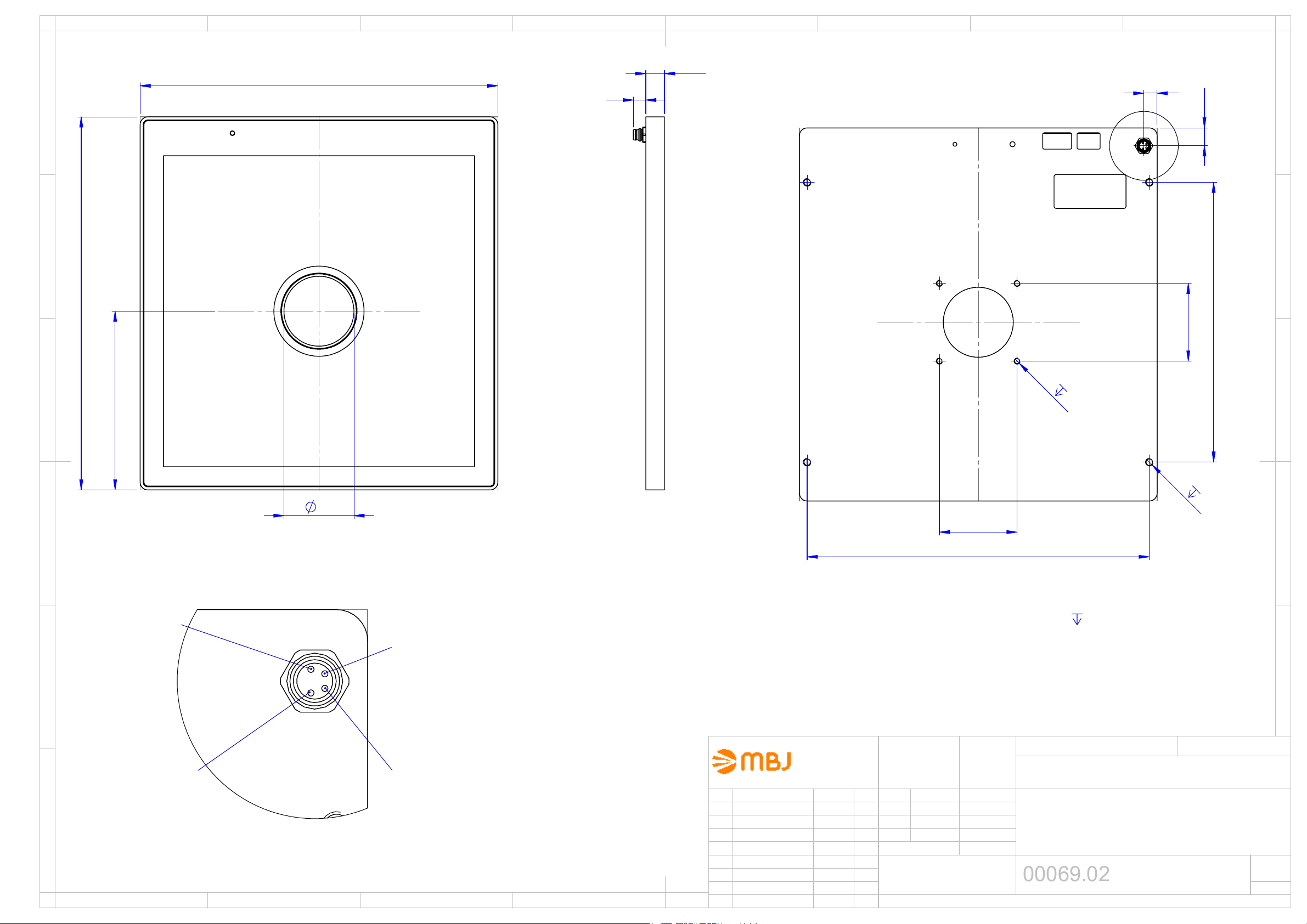
Mechanischer Einbau - Für die Befestigung der
Beleuchtungseinheit sind vier Montagebohrungen mit
Gewinde vorgesehen. Bitte die max. Einschraubtiefe nicht
überschreiten. Es kann zur Zerstörung des Gerätes führen.
Es ist auf ausreichende Wärmeableitung zu achten.
Benutzungshinweise – Bitte vermeiden Sie in Betrieb eine
mechanische Beanspruchung der Leuchtfläche. Dies kann
zu Kratzern und einem inhomogenen Lichtaustritt führen.
Reinigung – Die Leuchtfläche darf nur mit einem
handelsüblichen Glasreiniger und einem weichen Putzlappen
gereinigt werden.
1. Cautions and instructions for use
Please read the warning and application instructions carefully
before using the backlight.
General - The device is designed for indoor use only.
Health – Strictly avoid looking directly into the light source.
The lighting must be switched off before the installation
and/or maintenance. The device must not be used when a
failure may cause a personal injury.
Heat - In case of insufficient heat dissipation or supplying
to the device the max. flash voltage (Ub) is a continuous
operating mode (via the CTR series or directly) the surface
temperature may exceed 60 °C. Keep off flammable
materials at any time.
Electricity - The housing is electrically isolated from the
ground of the power supply. Exceeding the permissible input
voltage Uin or using the Ub input for steady light can lead to
the destruction of the device or to a significant shortening of
the lifetime of the LEDs of the device.
Mechanical integration - 4 screw-in tape holes can be used
to fix the lighting to specified position. It is essential to ensure
adequate heat transfer at the holding position. Please do not
exceed the maximum screw-in depth. It could destroy the
unit.
Usage – Please prevent during operation mechanical
stress to the light surface. This could lead to scratches and
inhomogenious light emission.
Cleaning - The light emission surface has to be cleaned
with a standard glass cleaner and a soft cleaning cloth only.
2. Elektrische Anschlüsse
Die Beleuchtung wird mit einem M8x1 Flanschstecker mit
vier Anschlüssen geliefert.
Pin Litzenfarbe
1)
Signalbeschreibung
1 Braun Uin = 24V DC (Dauerlicht)
2 Weiß Ub, LED+ (Blitzspannung)
2)
3 Blau Sense-Signal (MBJ-Controller)
4 Schwarz Masse, LED-
1) bei Verwendung der MBJ-Anschlusskabel.
2) Anschluss an einen externen LED-Controller (z. Bsp. Stromquelle)
der Betrieb ohne Stromquelle kann zur Zerstörung des Gerätes führen
2. Electrical connection
The lighting is supplied with a 4 pin M8x1 connector.
Pin Wire color
1)
Signal description
1 brown Uin = 24V DC (steady light)
2 white Ub, LED+ (flash voltage)
2)
3 blue sense signal (MBJ controller)
4 black Ground, LED-
1) for use with MBJ connecting cable
2) for connection to an external LED controller (e.g. current source)
running without current source may destroy the unit
3. Betriebsmodi
Die Beleuchtung kann
•im Dauerbetrieb über Uin = 24V DC oder im
•Blitzbetrieb über Ub bei höheren Strömem betrieben
werden. Ein LED-Controller ist hier erforderlich.
3. Operating mode
The illumination can be run
•with continuous light via the input Uin = 24V DC or
•with flash light via the input Ub with higher electric
current. In this case a LED flash controller is mandatory.
DTL-2020 Flat Dome Light Series
MBJ Imaging GmbH
Neuer Höltigbaum 15
DE 22143 Hamburg
support@mbj-imaging.com
www.mbj-imaging.com
Tel.: +49 40 226 1623 30
DTL-2020 Series
Release: 1.14
21.07.2017
4
.
Modellübersicht / LED
-
Farbe
LED Modell Wellenlänge
Weiß DTL-2020-WT Spitze bei 460nm & 560nm
Rot DTL-2020-RD Spitze bei 625nm
Blau DTL-2020-BE Spitze bei 455nm
InfraR DTL-2020-IR Spitze bei 880nm
5. Strombedarf
Mode Weiß Rot Blau IR
100%
1)
1,2A 0,8A 1,2A 750mA
200%
2)
2,4A 1,6A 2,4A 1,50A
300%
3)
3,6A 2,4A 3,6A 2,25A
1) Bei Verwendung von Uin=24V im Dauerlicht kann der Strom um ca. weiter 10% steigen.
2) Blitzbetrieb mit < 30% Auslastungsgrad <100ms Blitzzeit
3) Blitzbetrieb mit < 10% Auslastungsgrad <1ms Blitzzeit
6. Allgemeine Spezifikation
Leuchtfläche (axb) 200mm x 200mm
Lichtabstrahlung Auflicht mit diffuser
Abstrahlung und 45mm Loch
Empfohlener
Objektabstand
100mm bis 250mm,
abhängig vom Abbildungs-
maßstab, der Objektgröße und
der Beleuchtungsart
Betriebsspannung (Uin) 24V DC +/- 10%
Betriebsarten Dauerlicht oder Blitzbetrieb
Funktionen Rsense-Technologie zur auto-
matischen Modellerkennung
Max. Leistung im
Dauer (Uin) und
200% Blitzbetrieb Ub
WT/BE: 29Wsteady/ 46W pulse
RD: 19,2Wsteady/ 36,0W pulse
IR: 17,5Wsteady/20,0W pulse
Ub Spannungs-
bereich
WT/BE: ca.15V … 22V
RD: ca. 18V … 24V
IR: ca. 9V … 16V
Abmessungen 230mm x 240mm x 12mm
Gewicht 1200g
Anschluss M8x1 Buchse, 4pol, männlich
Umgebungs-
temperatur
10°C bis 30°C
Schutzart IP54
Luftfeuchtigkeit 30% bis 70%
Zubehör Siehe www.mbj-imaging.com
Webseite für diverse Kabel,
Halter und LED-Controller
4
.
Model Range / LED Color
LED Model wave length
White DTL-2020-WT peak near 460nm & 560nm
Red DTL-2020-RD peak near 625nm
Blue DTL-2020-BE peak near 455nm
InfraR DTL-2020-IR peak near 880nm
5. Operating current
mode White Red Blue IR
100%
1)
1.2A 0.8A 1.2A 750mA
200%
2)
2.4A 1.6A 2.4A 1.50A
300%
3)
3.6A 2.4A 3.6A 2.25A
1) Using the Uin=24V steady light the current could rise by add. 10%
2) Pulse mode with < 30% duty cycle and <100ms flash time
3) Pulse mode with < 10% duty cycle and <1ms flash time
6. General Specification
Luminous area (axb)
200mm x 200mm
Light emission
Diffuse incident light from
above and 45mm lens hole
Recommended
object distance
100mm to 250mm,
depending on reproduction
scale, the size of the object
and the type of illumination.
Operating voltage (Uin) 24V DC +/- 10%
Operating mode continuous or flash light
Functions Rsense technology for auto
detection of the LED lighting
Max. power in
continuous (Uin) and
200% flash mode Ub
WT: 29.0Wsteady/ 46.0W pulse
RD: 19.2Wsteady/ 36.0W pulse
IR: 17.5Wsteady/ 20.0W pulse
Ub voltage range WT/BE: approx.15V … 22V
RD: approx. 18V … 24V
IR: approx. 9V … 16V
Dimensions 230mm x 240mm x 12mm
Weight 1200g
Connector M8x1 socket, 4 pin, male
Operating
temperature
10°C to 30°C
Degree of protection IP54
Humidity 30% to 70%
Accessories For cable, mounts and LED
controller please check
www.mbj-imaging.com
DTL-2020 Flat Dome Light Series
MBJ Imaging GmbH
Neuer Höltigbaum 15
DE 22143 Hamburg
support@mbj-imaging.com
www.mbj-imaging.com
Tel.: +49 40 226 1623 30
DTL-2020 Series
Release: 1.14
21.07.2017
7
. Helligkeit
für weiße LEDs
Die Beleuchtungsstärke wurde beim jeweiligen Abstand im
Zentrum der beleuchteten Objektfläche als Näherungswerte
erfaßt.
Objekt-
Abstand
Dauerlicht
Mode
Blitzlicht
300%-Mode
10 mm --- ---
50 mm 17 klux 35 klux
100 mm 13 klux 30 klux
150 mm 10 klux 22 klux
200 mm 7 klux 18 klux
Angaben sind Näherungswerte mit +/-7% Toleranz
8. Mechanische Abmessungen
Siehe Zeichnung auf der folgenden Seite.
7
.
Illuminance
for white LEDs
The illuminance of the light is measure at the center point of
the object surface at the given distance and it is an
approximate value.
Object
distance
Steady light
mode
Flash light
(300%) mode
10 mm --- ---
50 mm 17 klux 35 klux
100 mm 13 klux 30 klux
150 mm 10 klux 22 klux
200 mm 7 klux 18 klux
Values are approximate with +/-7% tolerance
8. Mechanical dimensions
Please refer to the drawing on the next page.
230
240
115
45
max. screw-in depth
Light field 200x200
180
M5
9
220
50
M4
3
50
11,50
8,50
B
B (2 : 1)
M8x1 connector / Pin out
GND
Sense
Uin
U
B
12
8
C
6
7
5
8
B
A
D
E
F
Allgemein-
toleranzen
Datum
Name
Bearb.
24.2.14
F.Lorenz
Gepr.
Maßstab: 1:2
Gewicht:
DTL-2020
00069.02
Blatt
DIN A3
Verzeichnis: Z:\53 Zeichnungen\01 Einzelteile, Baugruppen\00069.02 DTL-2020.SLDDRW
Name
Datum
Änderung
Zust.
1/2
Schutzvermerk nach DIN 34 beachten
24.2.14
F.Lorenz
02
Erweitert für TLi, Ø45
25.11.15
F.Lo
DIN ISO 2768-m
1
2
3
4
1
2
3
4
A
B
C
D
E
MBJ Imaging GmbH
Neuer Höltigbaum 15
D-22143 Hamburg

This manual suits for next models

4

Popular Camera Accessories manuals by other brands

Westfalia 817033 instructions

Westfalia

Westfalia 817033 instructions

Exide GEL G85 manual

Exide

Exide GEL G85 manual

CyberPower BPE240V30ART3U user manual

CyberPower

CyberPower BPE240V30ART3U user manual

Ryobi BPL3650 Original instructions

Ryobi

Ryobi BPL3650 Original instructions

Axis AVTPSC specification

Axis

Axis AVTPSC specification

Vello FD-100 user guide

Vello

Vello FD-100 user guide

RRS BPC-16 quick start guide

RRS

RRS BPC-16 quick start guide

GeoVision GV-SD220-S installation guide

GeoVision

GeoVision GV-SD220-S installation guide

Saft 2506 Overhaul manual

Saft

Saft 2506 Overhaul manual

Miller 1036 Operator's manual

Miller

Miller 1036 Operator's manual

Livoo TEA271 user manual

Livoo

Livoo TEA271 user manual

Sanyo KR-1500SC Cadnica Specifications

Sanyo

Sanyo KR-1500SC Cadnica Specifications

Westcott 1866 Setup instructions

Westcott

Westcott 1866 Setup instructions

Energizer 346 Product data sheet

Energizer

Energizer 346 Product data sheet

Dometic BUTTNER MT LI 0085 Installation and operating manual

Dometic

Dometic BUTTNER MT LI 0085 Installation and operating manual

MPOWERD Viri instruction manual

MPOWERD

MPOWERD Viri instruction manual

TAKAMA TAKBS10 manual

TAKAMA

TAKAMA TAKBS10 manual

Vector Super SPORT SPOT Owner's manual & warranty information

Vector

Vector Super SPORT SPOT Owner's manual & warranty information

manuals.online logo
manuals.online logoBrands
  • About & Mission
  • Contact us
  • Privacy Policy
  • Terms and Conditions

Copyright 2025 Manuals.Online. All Rights Reserved.