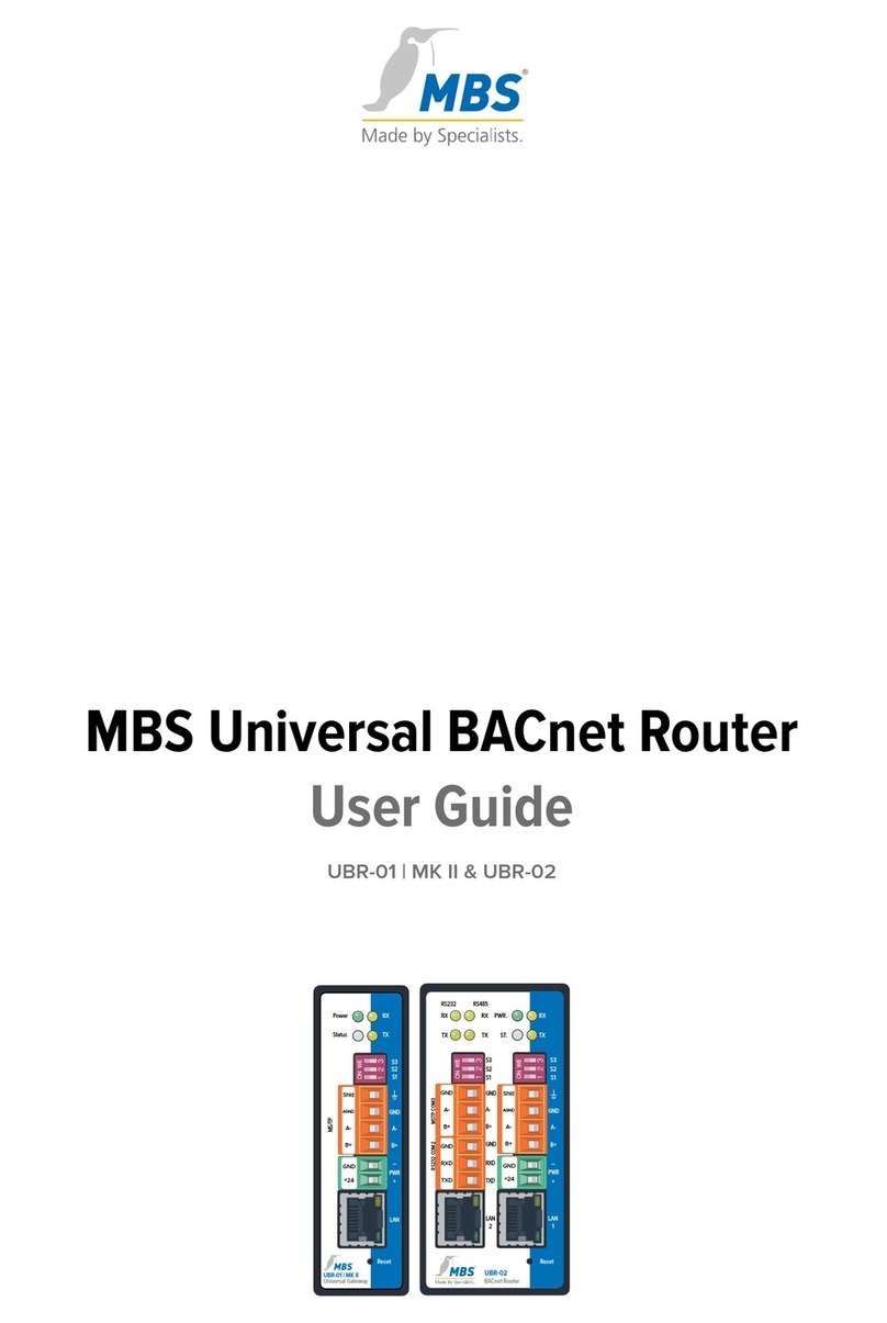
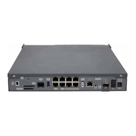
MBS UBR-01 MK II User manual

MANUAL
Universal BACnet Router
UBR-01 |Mk II
2021/09

MBS UBR-01 | Mk II Inhalt 2 von 46
Table of contents
1Introduction..............................................................3
2Safety.........................................................................5
3Classification and purpose...................................7
4Features....................................................................8
5Specifications and connected loads................ 12
6Installation .............................................................. 14
7Configuration..........................................................17
8Reset....................................................................... 45
9Product support ................................................... 46

MBS UBR-01 | Mk II Introduction 3 von 46
1Introduction
Notation and symbols used
Notice
The following notation and symbols are used in this manual.
<Buttons> The following notation and symbols
are used in this manual.
Graphic symbols are also used for
buttons where suitable.
Network commands as well as
file and product names
Network commands, such as
traceroute or ping, are written in
italics. The same applies to file and
product names.
Copyright protection This document is protected by copyright. Reproduction, reprinting,
even of extracts, as well as reproduction of the images, even in a
modified state, is only permitted with the written consent of the
manufacturer.
Warranty This manual must be read carefully before installing and
commissioning the device. The warranty entitlement lapses if the
device is installed by untrained personnel. Harm caused by
disregarding the allowable connected loads and ambient conditions or
by using unsuitable tools is also excluded.
Limitation of liability All information and notes in this manual were compiled taking the
applicable standards and regulations, best engineering practice and
the manufacturer's extensive knowledge and experience into
consideration.

MBS UBR-01 | Mk II Introduction 4 von 46
The manufacturer assumes no liability for indirect and direct damage
due to:
•Ignorance of this manual,
•Improper use,
•Use of untrained personnel,
•Damage due to incorrect installation,
•Unauthorized modifications to the hardware and software,
•Use of non-approved components.
The obligations agreed in the delivery contract, the general terms and
conditions as well as the manufacturer's delivery conditions and the
legal regulations applicable at the time of the conclusion of the
contract apply.
Target group This manual is intended for qualified personnel who are familiar with
the configuration of devices and networks in building and industrial
automation.
Intended use
The device is intended exclusively for coupling networks in building
and industrial
automation, with the connection values specified in the
technical data.
Notice
This manual is part of the product and must remain with the end
customer.

MBS UBR-01 | Mk II Safety 5 von 46
2Safety
General The hardware and software present no direct hazards. However, in
their function as a gateway between networks in building infrastruc-
tures, they are able to seriously disrupt the interaction of network
components.
Warning
Misconfiguration of hardware and software!
Faulty configuration of hardware and software can cause
malfunctions in the building infrastructure on network components,
sensors or actuators, for example:
•Monitoring devices, such as fire alarm or intrusion detection
systems, are deactivated.
•Machines and fans start up unexpectedly.
•Gate valves and other valves open or close unintentionally.
Under certain circumstances, this can lead to serious injuries or
death.
The configuration of the device may only be carried out by
qualified personnel who are familiar with the network
configuration!
No connection to a network may be established before the
device has been completely configured!

MBS UBR-01 | Mk II Safety 6 von 46
Warning
Electric shock hazard!
When installing and connecting the device, live parts of the overall
system in the control cabinet or other system parts may come into
contact.
Under certain circumstances, this can lead to serious injuries or
death.
Electrical devices may only be installed and connected by
qualified electricians.
Notice
Operation of this device may cause radio interference in
residential areas. In this case, the operator may be required
to take appropriate measures and to pay for them (EN 55032).

MBS UBR-01 | Mk II Classification and purpose 7 von 46
3Classification and purpose
Classification The devices of the UBR (Universal BACnet Router) product family, with
their different interfaces, serve as BACnet router between different
BACnet networks.
Purpose Router from BACnet IP to BACnet MS/TP. The router can be used as a
BACnet router to connect a MS/TP bus to a BACnet IP network.
Standalone BBMD
The router can act as a BBMD in BACnet networks. The BBMD
functionality is used to transport broadcast messages across network
boundaries (IP switches) and thus make them available in the other
subnet. Without the use of BBMDs, broadcast messages are not
transmitted over an IP switch.
Schematic structure of a typical BACnet network
1 Ethernet BACnet/IP
2 PC with projecting
software or building
control system
3 RS485 (two-wire network)
4 DDC automation station
5 MBS universal BACnet
router
6 DDC automation station
7 Field device, e.g. pump

MBS UBR-01 | Mk II Features 8 von 46
4Features
BACnet BACnet Protocoll Revision;
the router is compliant with BACnet version 1 protocol revision 22.
Diagnostics;
the router has extensive diagnostic capabilities to assist with
commissioning and to monitor function during operation.
BACnet-IP BBMD – BACnet Broadcast Management Device;
the router can be configured as a BACnet Broadcast Management
Device (BBMD). The connection of Foreign Device (FD) is supported in
BBMD mode.
FD – Foreign Device;
the router can be registered as a foreign device with a BBMD present
in the network. By the registration the router becomes part of the
BACnet/IP network and receives broadcast messages from other
subnets which are provided by the BBMD.
BBMD IP Filter;
using the BBMD-IP Filter function, it is possible to control from which
devices broadcasts are forwarded from the IP subnet via the BBMD
functionality. Individual devices can be excluded via the filters in order
to prevent broadcasts from these devices from being transported
beyond the limits of the IP subnet.
BACnet MS/TP The router works as a master on the MS/TP bus and supports the
following baud rates: 9,600 / 19,200 / 38,400 / 57,600 / 76,800 /
115,200.
The bus terminating resistor and the network bias resistors can be
activated via the DIP switch. The RS485 interface (BACnet MS/TP) is
potential-free.

MBS UBR-01 | Mk II Features 9 von 46
Slave Proxy The router can be configured as a "slave proxy" and responds to
"Who-Is" requests with an "I-Am" message on behalf of connected
MS/TP slave devices. The slave proxy option allows other BACnet
devices to find the connected MS/TP slave devices in the network
without having to configure the slave addresses in each device
individually.
In addition to manual configuration, the router also has the capability
of automatic configuration.
BACnet/SC
Topology
First of all, the network topology of BACnet/SC looks different.
Previously, broadcasts were used for initial
connection attempts in
BACnet, partly with the support of BACnet Broadcast Management
Devices (BBMD)
– not a commonplace method in the IT field.
A different approach has now been chosen for the configuration.
Each network is given a central point, the so
-called hub. It controls the
data traffic between any number of nodes (end devices). It also
analyzes the traffic to determine whether information should be
forwarded to a single node or to all nodes.
A direct connection can also be configured for direct communication
between
two nodes.
Furthermore, BACnet/SC includes a failover mechanism that ensures
that the system remains operational even if the hub fails or is switched
off for maintenance. This new
topology greatly simplifies
configuration, commissioning and management.
At the same time,
BBMDs and their configuration become obsolete.

MBS UBR-01 | Mk II Features 10 von 46
Structure of a typical BACnet/SC network
BACnet/SC
Encryption
and certificates
TCP (Transmission Control Protocol) and WebSocket – two reliable
mechanisms based on the internet protocol (IP) widely used in IT –
are used for secure data transmission. TCP/IP replaces the UDP
(User Data Protocol) network protocol layer previously used by
BACnet; TLS is used to ensure bug-proof and tamper-proof
communications. TLS (Transport Layer Security) is also widely used
as the foundation for secure internet access (https) in IT.
As far as encryption is concerned, a company-wide procedure must
be put in place for the necessary digital certificates.
The certification and registration authorities responsible for the
internet in connection with public key infrastructures are not
specified in BACnet/SC. This means building automation operators
can take account of their individual network structures.

MBS UBR-01 | Mk II Features 11 von 46
To ensure problem-free implementation in existing networks, the
security mechanisms have been defined in BACnet as an additional
data link layer.
The new standard in the latest revision 22is also downwardly
compatible. The advantage of this is that the existing system can
always communicate with the new BACnet/SC devices via
appropriate routers.
Notice
The configuration of BACnet/SC connections is described in this
document under BACnet settings (page 32).

MBS UBR-01 | Mk II Specifications and connected loads 12 von 46
5Specifications and connected loads
Casing Metal casing for top-hat rail mounting
Protection class IP20
Assembly DIN top-hat rail TS35 according to
EN 60715
Weight 250 grams
Ambient temperature 0–45 °C, 32–113 °F
H/W/D dimensions
in millimeters
100 / 30 / 70
(including DIN top hat rail adapter)
Lateral spacing
to other devices ≥ 15 mm
Ambient humidity 20–80 percent relative humidity,
non-condensing
Power supply
9-24 volts DC or 9-24 volts AC, 200 mA,
wide range input, protective extra-low
voltage (PELV), LED for indication of
power supply
Power consumption 1,7 watts
Ethernet 10/100 Mbit, TP RJ45 socket
MS/TP
4-pole Weidmüller socket with the
connections:
B(+), A(-), SGND (Signal Ground), SHLD
(cable shield)
LED TX and RX to display sending and
receiving data

MBS UBR-01 | Mk II Specifications and connected loads 13 von 46
Notice
Operation of this device may cause radio interference in
residential areas. In this case, the operator may be required
to take appropriate measures and to pay for them (EN 55032).

MBS UBR-01 | Mk II Installation 14 von 46
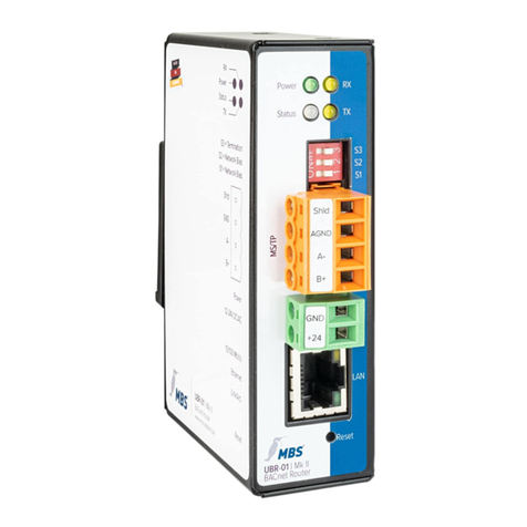
6Installation
1 LED
Power Power supply status
RX Receiving data MS/TP
TX Send data MS/TP
Status Router status (Multicolor LED)
2 DIP switch
S1 Bias voltage
for RS485 interface
S2 Bias voltage
for RS485 interface
S3 120 Ohm
termination impedance
3 MS/TP RS485
Shld Shielding
SGND Signal ground
A-Inverted wire
B+ Non-inverted wire
4 PWR
GND, ground
Supply voltage 12-24 V,
DC or AC, PELV
5 LAN Ethernet RJ45
5.1 LED 10/100 Mbit/s
5.2 LED Link/Activity
6 Reset
2
3
5.1
5
6
1
4
5.2

MBS UBR-01 | Mk II Installation 15 von 46
Assembly / Disassembly The device must be mounted on a top-hat rail (DIN top hat TS35
according to EN 60715). The top-hat rail bracket is pre-assembled on
the back of the device. The bracket is hooked into the top-hat rail from
above and fixed to the underside of the bracket with a clearly
perceptible click.
Warning
Electric shock injury hazard!
The device may only be installed in a control cabinet (top-hat rail)
when the power is disconnected.
The system must be disconnected for installation.
Notice
A sufficient distance (≥ 15 mm) to the other components on the top
hat rail is recommended for mounting the device in the control
cabinet.
This ensures better heat dissipation, which can have a positive
influence on the service life of the device.
Disassembly is carried out by unlocking the bracket on the underside
and carefully removing it from the top-hat rail.
Notice
Connecting cables should be unplugged during disassembly, to
avoid damage.
Power connection The device is exclusively operated with protective extra low voltage
(PELV). The permissible voltage range must be taken from chapter 5
Specifications and connected loads.

MBS UBR-01 | Mk II Installation 16 von 46
Warning
Electric shock injury hazard and damage to device!
Connecting the device to deviating, excessively high supply
voltages may lead to serious injuries or death.
The device is operated exclusively with Protective Extra-Low
Voltage. No supply voltages that deviate from the connection
values specified in the Specifications and connected loads may
be used.
The device is supplied with a reverse polarity protected plug that is
already pre
-
assembled in the [PWR] socket. To connect the supply lines,
it is recommended to remove the plug. The cable cores are connected
and screwed
according to the marking [+24 / GND].
RS485 Bias voltage The bias voltage for the RS485 interface is switched with the DIP
switches S1 and S2. The bias voltage is active when they are both set
to the ON position. The default setting for all DIP switches is OFF..
Notice
Switches S1 and S2 must always be switched together to avoid
transmission interference on the MS/TP bus.
RS485 Bias termination S3 provides a switchable 120 Ohm terminating resistor that terminates
the end of a segment in an MS/TP network. Termination may only be
done when the device is at the end of such a network segment.

MBS UBR-01 | Mk II Configuration 17 von 46
7Configuration
Network connection For configuration, the device must be connected to the computer
using a network cable.
The computer then automatically (APIPA) receives a free IP address in
the address range 169.254.x.x and can communicate directly with the
device.
If there is no direct (point to point) connection between the device and
the computer or if the IP address is not assigned automatically, it must
be configured manually on the computer (e.g. IP address 169.254.0.5 /
subnet mask 255.255.0.0).
Notice
It is important that the manually configured IP address is not already
in use by other devices on the network.
The way to configure the network connection on the computer
depends on its operating system.
Under factory settings, the web server is accessible at the following IP
address:
IP address 169.254.0.1
Subnet mask 255.255.0.0
Web server The device has an integrated web server for configuration. The web
server provides the configuration settings in the form of websites.
Login To call up the configuration interface, the following address is entered:
http://169.254.0.1 or https://169.254.0.1
To log in to the web server for the first time, the user name and the
preset password must be entered.

MBS UBR-01 | Mk II Configuration 18 von 46
User name admin
Password admin
Password security After logging in, it is strongly recommended to change the password
and keep it safe.
Important notice
The preset password cannot be restored by a hardware reset!
Passwords can be reset only if the SSH option has been enabled
before.
HTTPS For a connection via https (Hypertext Transfer Protocol Secure), the
device has its own security certificate when delivered.

MBS UBR-01 | Mk II Configuration 19 von 46
Usage
Hinweis
To be compliant with this guide, set the language of the web server
to English by clicking the icon.
Hinweis
To update the views in the web server, the REFRESH button must
always be used.
If the refresh button of the web browser is used, the web server will
be logged out.
Some configurations require the device to be restarted. This is
indicated in these instructions with <restart required>. The web
server shows at the top of the screen of the adjacent button.
Menu structure The menu structure of the web server is described in this manual in
the categories GENERAL / BACNET / DIAGNOSTICS / HELP. These
categories are structured into their corresponding subitems.

MBS UBR-01 | Mk II Configuration 20 von 46
GENERAL
Overview Shows basic device data and the current system status. The device
data can be changed under General / Details.
Type: Device type
Name: Designation
Location: Installation location
Description: e.g. Universal BACnet Router
System start: last system start
CPU load: current CPU load
Free system memory: free / occupied in MByte
Other manuals for UBR-01 MK II
1
Table of contents
Other MBS Network Router manuals
