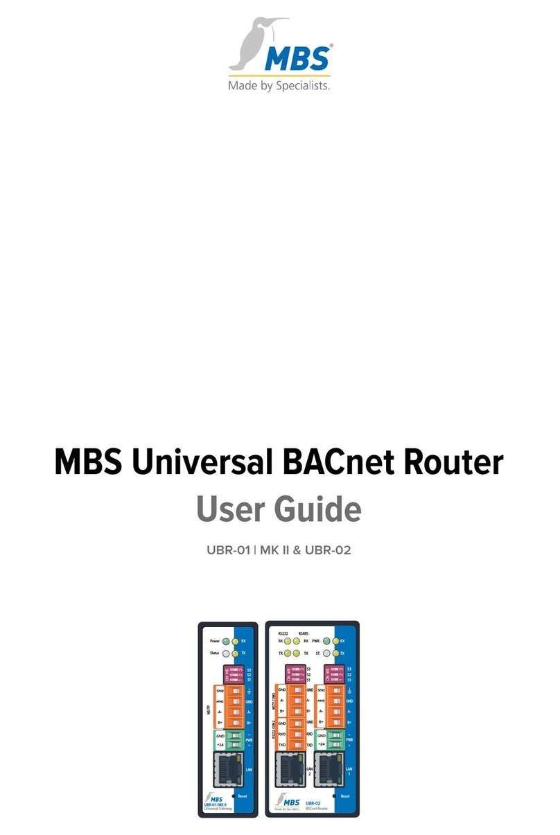
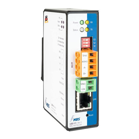
MBS X Series User manual

Quick Start
Universal BACnet Router
Universal Gateway
2020/07

2 of 12
Table of contents
1Introduction.............................................................. 3
2Safety ........................................................................ 4
3Specifications.......................................................... 5
Mechanical data ...................................................................................5
Ambient conditions..............................................................................5
Power supply BACnet Router ...........................................................5
Power supply Gateways X-Serie......................................................5
Power supply Gateways A-Serie......................................................6
Network connection for configuration............................................6
4Installation................................................................ 6
5Configuration........................................................... 8
Connection to the device...................................................................8
Configuration interface.......................................................................9
Reset...................................................................................................... 10
6Product support....................................................11
7Notes.......................................................................12
Imprint
Manufacturer: MBS GmbH, Römerstraße 15, 47809 Krefeld
; Managing Director: Martin Brust-Theiß, Gerhard Memmen-Krüger, Nils-Gunnar Fritz; Register court: Krefeld HRB 3337
;
USt.
-IdNr: DE 120 148 529; Headquarters: Krefeld; Responsible for contents according to § 5 TMG such as § 55 RStV: Martin Brust-Theiß, Gerhard Memmen-Krüger, Nils-Gunnar Fritz

3 of 12
1Introduction
Quick Start
This manual enables the basic installation and configuration work
to be carried out on the device.
It must be read carefully before installation and
commissioning.
Comprehensive information is provided online in the manual for
the respective device:
www.
mbs-solutions.de/dokumentation
Target group
This manual is intended exclusively for specialist personnel who
are familiar with gateway and
router configuration in building
automation.
Intended use
The device is only intended for the coupling of networks in
building and industrial automation with the connection values
specified by the manufacturer.

4 of 12
2Safety
The hardware and software present no direct hazards. However,
in their function as a router or gateway between networks in
building infrastructures, they are able to seriously disrupt the
interaction of network components.
Warning
Misconfiguration of hardware and software!
Faulty configuration of hardware and software can cause
malfunctions in the building infrastructure on network
components, sensors or actuators, for example:
•Monitoring devices, such as fire alarm or intrusion
detection systems, are deactivated.
•Machines and fans start up unexpectedly.
•Gate valves and other valves open or close unintentionally.
Under certain circumstances, this can lead to serious injuries
or death.
The device should only be configured by specialist
personnel who are familiar with network configuration!
A connection to a network must not be established before
the device has been fully configured!

5 of 12
3Specifications
Mechanical data
Casing Metal casing for top-hat rail mounting
Assembly DIN top-hat rail TS35
in accordance with EN 60715
Weight depending on type, see manual
H/W/D dimensions depending on type, see manual
Ambient conditions
Ambient temperature 0…45°C, 32…113°F
Ambient humidity 20 to 80 percent relative humidity,
non-condensing
Recommended lateral
spacing
≥ 15 mm to other devices on the
top-hat rail
Power supply BACnet Router
UBR-01 | Mk II Wide range input
12 to 24 Volt direct voltage or
12 to 24 Volt alternating voltage
UBR | LON
UBR-02
Power consumption depending on type, see manual
Power supply Gateways X-Serie
Single-X Wide range input
12 to 24 Volt direct voltage or
12 to 24 Volt alternating voltage
Double-X
Triple-X
Power consumption depending on type, see manual

6 of 12
Power supply Gateways A-Serie
maxi | Mk II, Single-A +12 to +24 Volt direct voltage
tolerance +/- 15%
PELV
maxi | Mk II, Double A
Power consumption depending on type, see manual
Network connection for configuration
Ethernet 10/100 Mbit, RJ45 socket
4Installation
Warning
Electric shock injury hazard!
The device may only be installed in a control cabinet (top-hat
rail) when the power is disconnected.
The system must be disconnected for installation.
Assembly / Disassembly The device must be mounted on a top-hat rail (DIN top hat TS35
according to EN60715). The top-hat rail bracket is pre-assembled
on the back of the device. The bracket is hooked into the top-hat
rail from above and fixed to the underside of the bracket with a
clearly perceptible click.
Notice
A sufficient distance (≥ 15 mm) to the other components on the
top-hat rail is recommended for mounting the device in the
control cabinet.
This ensures better heat dissipation, which can have a positive
influence on the service life of the device.

7 of 12
Disassembly is carried out by unlocking the bracket on the
underside and carefully removing it from the top-hat rail.
Notice
Connecting cables should be unplugged during disassembly,
to avoid damage.
Power connection The device is exclusively operated with protective extra low
voltage. The permissible voltage range depends on the
type of device and must be taken from chapter 3 Specifications.
Warning
Electric shock injury hazard and damage to device!
Connecting the device to deviating, excessively high supply
voltages may lead to serious injuries or death.
No supply voltages that deviate from the connection values
specified in the technical data may be used.
The device is supplied with a reverse polarity protected plug that
is already pre
-assembled in the [PWR] socket.
To connect the supply lines, it is recommended to remove the
plug.
The cable cores are connected and screwed according to
the marking [
+24 / GND].

8 of 12
5Configuration
Connection to the device
Web server The device has an integrated web server for configuration. The
web server provides the configuration settings in the form of
websites.
Under factory settings, the web server is accessible at the
following IP address:
IP address 169.254.0.1
Subnet mask 255.255.0.0
Network connection For configuration, the device must be connected to the computer
using a network cable.
The computer’s LAN connection must be configured correctly. To
set the network address manually, define the IP address as
169.254.0.2, for example. The subnet mask must match that of the
device.
Notice
If the device is connected directly to the computer via a
network cable, a connection is usually established via
Automatic Private IP Adressing (APIPA).
The IP address of the computer is then automatically in a
reserved address range of 169.254.x.x and enables a direct
connection to the gateway without manual network
configuration.

9 of 12
Configuration interface
To open the configuration interface, the following address is
entered in a web browser:
http://169.254.0.1 or https://169.254.0.1
Logging on To log in to the web server for the first time, enter the user name
and the preset password.
Universal BACnet Router
User name admin
Password admin
Universal Gateway
User name gw
Password GATEWAY
The password can be changed on the configuration pages (Menu
item GENERAL / USER /…).
Notice
The “REFRESH” symbol must always be used to update the
screen in the web server.
Using the web browser’s standard refresh button will log you
out of the web server.
All changes must be saved by clicking <Save>. Following
changes to the network configuration, it is sometimes
necessary to restart the gateway.
Certain configurations require the device to be restarted. This
is indicated in this manual with <Restart required>. The web
server will show at the upper edge, this button.

10 of 12
Further configuration The configuration of the respective device is explained in the
associated manual. The manual is available online at
www.mbs-solutions.de/dokumentation.
Reset
Hard-Reset With the hardware-reset button, the device can also be reset without
calling up the configuration interface.
Notice
You can find the reset button on the front of the device. The
reset button can only be pushed with a suitable tool.
The following changes are made depending on how long you hold
the button for.
1...5 seconds Restart (Reset-LED will flash red)
up to 10 seconds
The IP address will be set to 169.254.0.1
(default) until the next restart
(reset LED will flash green).
Soft-Reset This reset is carried out via the configuration interface. Details on
this are explained in the device manual.

11 of 12
6Product support
Manufacturer
MBS GmbH
Römerstraße 15
47809 Krefeld
Telephone +49 21 51 72 94-0
Fax +49 21 51 72 94-50
E-Mail support@mbs-solutions.de
Internet www.mbs-solutions.de
wiki.mbs-software.info
Service times Monday to Friday: 8:30 to 12:00
13:00 to 17:00

12 of 12
7Notes
This manual suits for next models
8
Table of contents
Other MBS Network Router manuals
Popular Network Router manuals by other brands
TP-Link
TP-Link Archer C2 Quick installation guide
Linksys
Linksys BEFSX41 - Instant Broadband EtherFast Cable/DSL Firewall... Product data

Linksys
Linksys WET11 - Instant Wireless EN Bridge Network... Specifications
Billion
Billion BiPAC 7300VGP Specifications
Teldat
Teldat Connect 104KF TLDPM00A1 installation manual
Enterasys
Enterasys SecureStack A2 A2H124-24P Hardware installation guide
