McConnel MAGNUM 130 Product manual

MAGNUM
FLAIL MOWER/SHREDDE
R
Models 130, 170, 190 & 225
Publication 408
January 2002
Part No. 41570.09
OPERATOR AND PARTS MANUAL

IMPORTANT
VERIFICATION OF WARRANTY REGISTRATION
DEALER WARRANTY INFORMATION & REGISTRATION VERIFICATION
It is imperative that the selling dealer registers this machine with McConnel Limited within
7 days of delivery to the end user – failure to do so may affect the validity of the machine
warranty.
To register machines go to the McConnel Limited web site at www.mcconnel.com, log
onto ‘Dealer Inside’ and select the ‘Machine Registration button’which can be found in
the Service Section of the site. Confirm to the customer that the machine has been
registered in the section below.
Should you experience any problems registering a machine in this manner please contact
the McConnel Service Department on 01584 875848.
Registration Verification
Dealer Name:
……………………..…………………………………………………………….
Dealer Address: …….………………………………………………………………………….
Customer Name: ……………………..…………………………………………………………
Date of Warranty Registration: ……/……/...…… Dealer Signature: ………………..……
NOTE TO CUSTOMER / OWNER
Please ensure that the above section above has been completed and signed by the selling
dealer to verify that your machine has been registered with McConnel Limited.
IMPORTANT: During the initial ‘bedding in’ period of a new machine it is the customer’s responsibility
to regularly inspect all nuts, bolts and hose connections for tightness and re-tighten if required. New
hydraulic connections occasionally weep small amounts of oil as the seals and joints settle in – where
this occurs it can be cured by re-tightening the connection – refer to torque settings chart below. The
tasks stated above should be performed on an hourly basis during the first day of work and at least
daily thereafter as part of the machines general maintenance procedure.
TORQUE SETTINGS FOR HYDRAULIC FITTINGS
HYDRAULIC HOSE ENDS PORT ADAPTORS WITH BONDED SEALS
BSP Setting Metric
BSP Setting Metric
1/4” 18 Nm 19 mm 1/4” 34 Nm 19 mm
3/8” 31 Nm 22 mm 3/8” 47 Nm 22 mm
1/2” 49 Nm 27 mm 1/2” 102 Nm 27 mm
5/8” 60 Nm 30 mm 5/8” 122 Nm 30 mm
3/4” 80 Nm 32 mm 3/4” 149 Nm 32 mm
1” 125 Nm 41 mm 1” 203 Nm 41 mm
1.1/4” 190 Nm 50 mm 1.1/4” 305 Nm 50 mm
1.1/2” 250 Nm 55 mm 1.1/2” 305 Nm 55 mm
2” 420 Nm 70 mm 2” 400 Nm 70 mm

EC DECLARATION OF CONFORMITY
Conforming to EEC Machinery Directive 98/37/EC*
We,
McCONNEL LIMITED,
Temeside Works, Ludlow, Shropshire SY8 1JL.
Declare under our sole responsibility that:
The product (type) ……………………………………………………………………
Tractor Mounted Flail Mower / Shredder
………………………………………………………………………………………….
Product Code …………………………………………………………………………..
MA13, MA17, MA19, MA225
Serial No. & Date ……………………………………. Type …………………………
Manufactured by the above company/* ………………………………………
………………………………………………………………………………………….
(* insert business name and full address if not stated above)
Complies with the required provisions of the Machinery Directive 98/37/EC, *
previously Directive 89/392/EEC as amended by Directives 91/368/EEC, 93/44/EEC
and 93/68/EEC.
The machinery directive is supported by;
•BS EN ISO 12100:2003 Safety of Machinery. This standard is made up of two
parts; Part 1 Terminology, methodology, Part 2 Technical Specifications.
•BS EN 1050 Safety of machinery - Principles of risk assessment.
•and other national standards associated with its design and construction as
listed in the Technical File.
The Machinery Directive is fully implemented into UK law by means of the Supply
of Machinery (Safety) Regulations 1992 (SI 1992/3073) as amended by The Supply
of Machinery (Safety) (Amendment) Regulations 1994 (SI 1994/2063).
Signed …………………………..……………………………………………………...
on behalf of McCONNEL LIMITED Responsible Person
Status: Chief Design Engineer Date: 25th January 2005

1
CONTENTS Pa
g
e
1. GENERAL INFORMATION 2
1.1. Introduction. 2
1.2. Identifying the machine. 2
2. TECHNICAL FEATURES 3
2.1. General description. 3
2.2. Technical Specifications. 4
2.3. Width of cut. 4
2.4. Equipment. 4
3. SAFETY RULES 6
3.1. General safety rules. 6
3.2. Safety rules - concerning road traffic. 6
3.3. Safety rules - during use. 7
3.4. List of guards. 7
3.5. Description and location of safety decals. 8
4. INSTRUCTION FOR INSTALLATION AND HANDLING 9
4.1. Lifting and unloading. 9
4.2. Unpacking. 9
4.3. Attachment and detachment from the tractor. 9
4.4. Fitting the PTO shaft. 10
4.5. Tractor stability. 11
4.6. Parking. 11
5. ADJUSTMENT AND SETTING UP 12
5.1. Regulating the height of cut. 12
6. USE AND OPERATING RULES 12
6.1. Starting. 12
6.2. Working mode. 12
6.3. Side shift - Non hydraulic models 12
6.4. Side shift - Hydraulic models 13
6.5. Stopping. 13
6.6. Transport position. 13
7. MACHINE MAINTENANCE 14
8. TROUBLE SHOOTING 15
9. REPLACING PARTS 15
9.1. Flail replacement. 15
9.2. Belt replacement. 16
10. DEMOLITION & DISPOSAL 16
11. SPARE PARTS SECTION 17
Magnum 130 18
Magnum 170 22
Magnum 190 & 225 26

2
1. GENERAL INFORMATION
1.1 Introduction
This operation and maintenance manual is intended for the professional user. It is
mandatory to follow these instructions in order to prevent events which could
endanger the operator’s and other people’s safety, apart from the correct functioning
of the shredder. In case of doubt, do not experiment, call McConnel after-sales
service instead, or the specialised McConnel dealer.
1.2 Identifying the machine
Each shredder is fitted with an identification plate: both the data necessary to identify
the model and the serial number to order spare parts or after-sales service are stamped
on the plate.
It is strongly recommended to use genuine spare parts to avoid altering the technical
features of the shredder. McConnel is not responsible for any damage or injuries to
people due to unauthorized modifications or the use of non-genuine spare parts.
This machine is in conformity with the following provisions of law:
Directive Machine 89/392/CEE and following additions:
91/368/CEE, 93/44/CEE and 93/68/CEE;
Regulations UNI EN 292/1 and 292/2 (machinery safety).
3
2. TECHNICAL FEATURES
2.1. General description
The Magnum mower, from now also called machine, has been designed for
cutting grass on amenity areas, in orchards and for cutting crop residues on small
agriculture areas, for sticks and shrubs laying on the ground of up to 3 cm diameter
(proper use)
Its light weight and low power requirement means that it is best suited to small
tractors. Any other use is considered improper and the manufacturer disclaims all
responsibility for any consequential injuries to people, or for damage to the machine.
Proper use also refers to the safety and maintenance rules provided for by the
manufacturer.
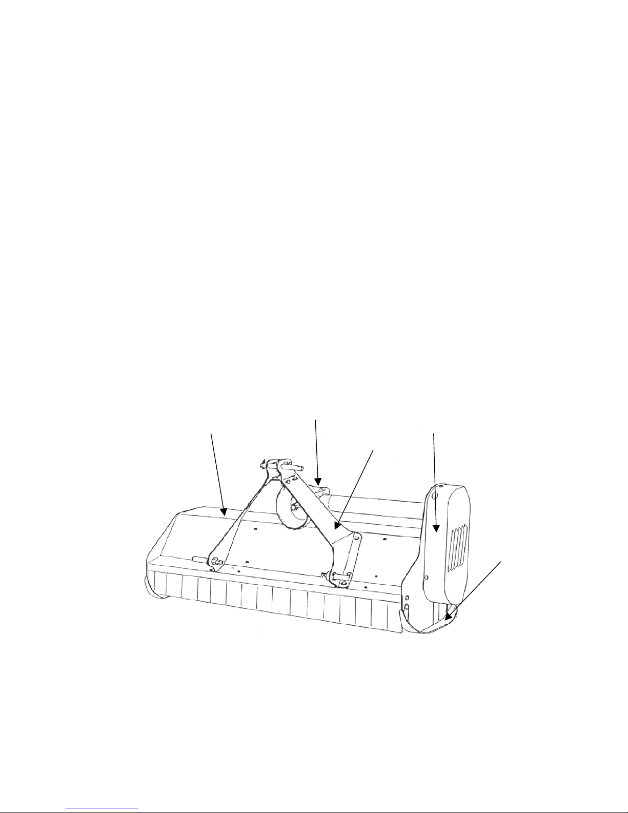
Technical names (see diagram below)
1 - frame
2 - gearbox
3 - connecting bow
4 - side transmission
5 - rear adjustable roller
6 - adjustable skids
7 - blades or hammers
1
2
3
4
6
4
EQUIPMENT 130 170 190 225
Hammer. Std. -Std. Std.
Y-Blades, flails. Opt. Std. Opt. Opt.
Fine cut blades - Opt. Opt. Opt.
Rear roller. Std. Std. Std. Std.
Mechanical side movement
2 fixed positions.
Hydraulic side movement -Opt. Opt. Opt.
Std. = Standard Equipment Skids -Opt. Opt. Opt.
Opt. = Optional Equipment Hydraulic rotary side cutter -Opt. Opt. Opt.
Std. Std.Std. Std.
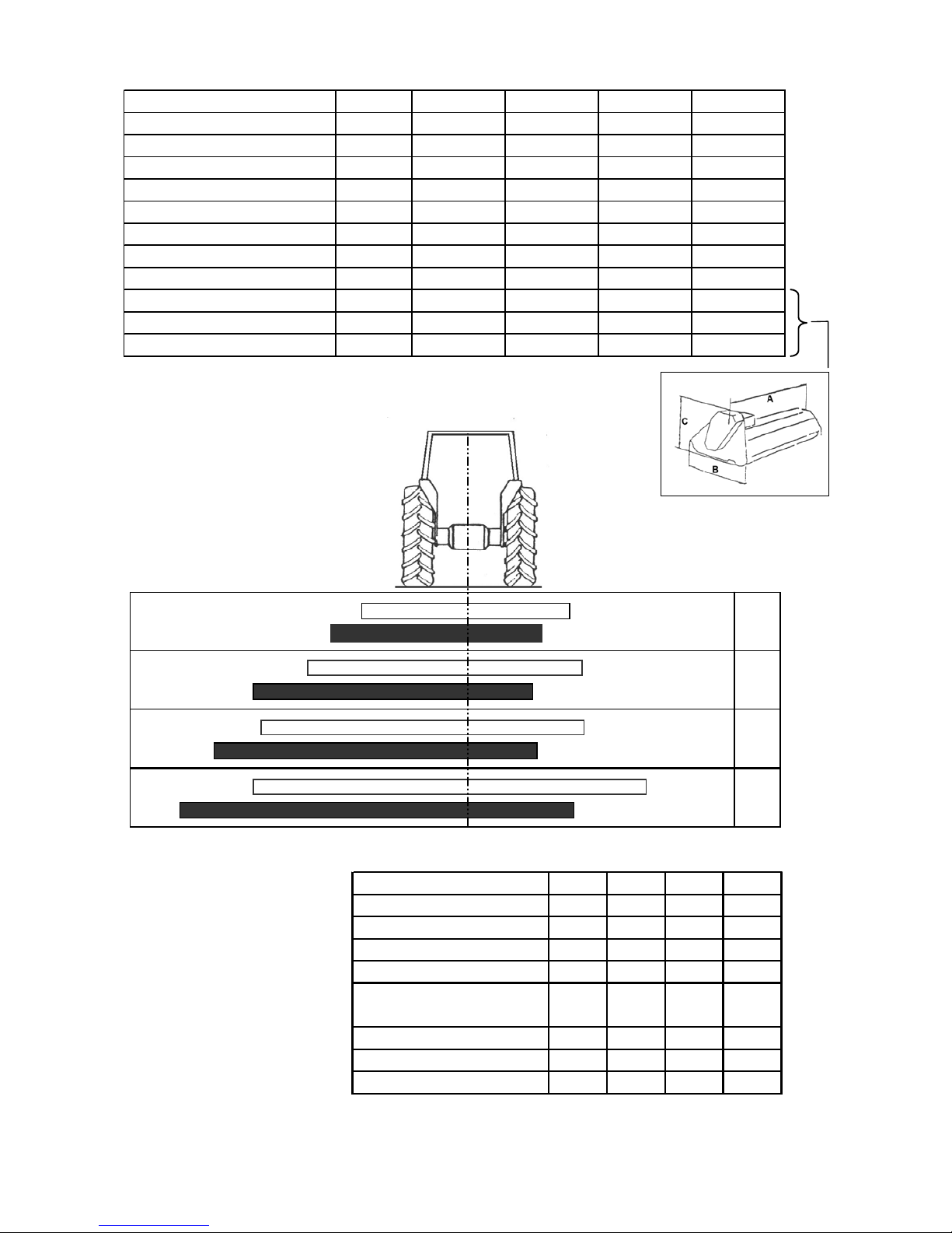
2.2 Technical Specification
2.3 Width of cut
2.4 Equipment
65 65
50
80
126 42
82
86
106
121
161 66
150 42
82
110
130
170
190
225
SPECIFICATION 130 170 190 225
Width of cut. cm. 130 168 191 226
M in. re q'd.tractor powe r. KW/HP 23-27/30-35 30-38/40-50 34-38/45-50 42-45/55-60
PTO speed. rpm. 540 540 540 540
Weight. kg. 185 285 385 427
Tractor attachment. Cat. II II II II
Flails. No.36724856
Scoop blades N/A N/A 36 N/A N/A
Hammer blades. No.18202428
Width 'A' cm. 145 188 208.5 243.5
Length 'B' cm. 80 76 100 100
He ight 'C' cm. 80 80 100 100

5
FOR NOTES

6
3. SAFETY RULES
3.1 General safety rules:
• It is mandatory to read and follow the instructions for the use and maintenance
manual before carrying out any operation or move with the shredder.
• Improper use or an incorrect move may seriously damage things and people.
• Both the operator and the maintenance fitter must know the shredder well,
especially regarding dangers resulting from improper use or incorrect repairs.
• Before starting, checks on tractor and shredder, must be carried out as regards:
functionality, road safety, accident prevention rules.
• Even when using the shredder correctly, stones or other objects may be thrown a
long distance. Therefore nobody must stand within the danger area. Special
attention must be paid when working near roads or buildings.
• Use tractor with cabs.
• The condition of flails and of all guards must be checked before beginning the
daily work - they must be replaced if damaged or missing.
• During checks or repairs, make sure nobody could start the shredder by mistake,
• Never wear loose or fluttering clothes.
• Never carry passengers on the tractor.
• Never carry passengers on the shredder.
• Never connect the power takeoff with the engine running.
• Never approach the shredder until the rotor has completely stopped.
• Do not enter the working zone of the PTO shaft. It is dangerous to approach the
rotating parts of the machine.
• Keep the PTO shaft guard in good order.
• Before starting check the surrounding area for the likely presence of children
and/or animals.
• Do not stand in the range of the operation of the machine.
• The PTO shaft must be assembled and disassembled only with the engine stopped
and the starting key removed.
• Before connecting the power takeoff, check that the speed and the rotational
direction correspond to those of the shredder.
• Before leaving the tractor with the tool attached, proceed as follows:
1. Disconnect the power takeoff,
2. Put the machine steadily on the ground (with the hydraulic lift)
3. Apply the hand brake and, if the ground is steeply sloping, wedge the tractor.
4. Take out the starting key.
• Immediately replace any safety sign, or any missing or damaged decal.
3.2 Safety Rules concerning Road Traffic
• In transport, reduce speed, especially on bumpy roads. The very weight of the
shredder may render driving difficult and damage the shredder itself.
• Check moreover that the levers that operate the hydraulic lift are locked, to avoid
the lowering of the machine during transport.
• When driving on public roads, respect all road rules in force.
• Never transport the shredder with the rotor moving, even for short distances.

7
3 12
4
5
3.3 Safety Rules during use
• Pay special attention when working with the machine, not to touch fixed objects,
such as road drain, walls, shafts, kerbs, guard rails, tracks etc. This could cause the
breakage of the flails, which would be thrown at very high speed.
• If wires, ropes or chains should get entangled in the rotor, stop immediately, to
prevent damage or dangerous situations; stop the rotor and the tractor, take out the
starting key. Put working gloves on, clear the rotor with the aid of pliers or shears.
Do not try to disentangle by inverting the rotational direction of the rotor.
• Do not use the machine when there is vibration in the flail head, as this would
cause breakage and serious damage. Find the cause of the vibration and eliminate
it.
3.4 List of Guards fitted to the shredder (see diagram below).
1. PTO shaft guard
2. Belt guard
3. Danger and warning decals
4. Front guard
5. Side guard-skids

8
3.5 Description and location of Safety decals
Carefully follow the instructions given on the decals (see illustrations below).
1. Always take the machine off the tractor and read the instructions carefully before
starting servicing and/or lubricating operations.
2. Keep at a safety distance from the machine to avoid the risk of projection of
objects.
3. Never remove the guards while the parts of machine are moving. It is dangerous
and may cause injury to hands.
4. Keep at a safety distance from the machine to avoid the risk of cutting feet.
5. It is forbidden to mount on the machine because of the risk of fall.

9
4. INSTRUCTIONS FOR INSTALLATION AND HANDLING.
4.1 Lifting and unloading
To handle the shredder use a hoist or crane with a lifting capability suitable to the
weight of the machine (see technical specifications on page 4).
4.2 Unpacking
To make transport easier, the machine can be supplied with connecting bow split In
this case use bolts, locknuts and washers enclosed to fix the bar and the flap on the
machine.
4.3 Attachment to and detachment from the tractor
Before carrying out this operation and whenever the shredder is used, it is mandatory
to:
• Visually check the machine in general.
• Check that all guards are fitted and in good condition.
• Confirm that all flails are fitted and in good condition.
• Grease the bearings and any other part as indicated by the decal.
• Check that the number or revolutions and the rotational direction of the power
takeoff correspond to those required by the machine (see diagram below).
• To attach the machine to the tractor (see illustration on page 10) bring the tractor
lower links (1) near the machine, to the points corresponding to the pins.
• Insert the pins (2) and secure them with the spring clips (3).

10
5
4 cm
4
4
3
1
6
• Fit the top link (4), raise the machine to a perpendicular position with the ground.
Adjust the two tractor lower linkage stabilizers (3) thus fixing the machine to the
tractor in a central position.
• Proceed in reverse order to detach the shredder from the tractor.
4.4 Fitting the PTO shaft
• Following the Instructions in 4.3 assemble the PTO shaft (6) and check that the
overlap is not less than 2/3 of L. Be sure to keep a 4 cm backlash (see illustration
above) if it needs shortening, proceed as shown below (see illustration).
• The guards of the PTO shaft must be fixed to the machine and to the tractor with
chains, to prevent rotation. The minimum overlap of the guard and the PTO shaft
must not be less than 5 cm. (see illustration below).

11
4.5 Tractor stability
Due to the design of the mowers and the work they do, it is essential to ensure tractor
stability, in order to eliminate any risk of imbalance or overturning.
• Lift the machine and check that the tractor does not mount up. In case it does,
ballast the rear wheel of the tractor opposite to the extended machine and at the
front of the tractor (see illustration below).
4.6 Parking
• Park the machine in a safe place, on flat and firm ground in order to prevent the
risk of rolling over.
• Lower the shredder to the ground with the aid of the hydraulic lift of the tractor.
(see illustration below).
12
= 1-3 cm
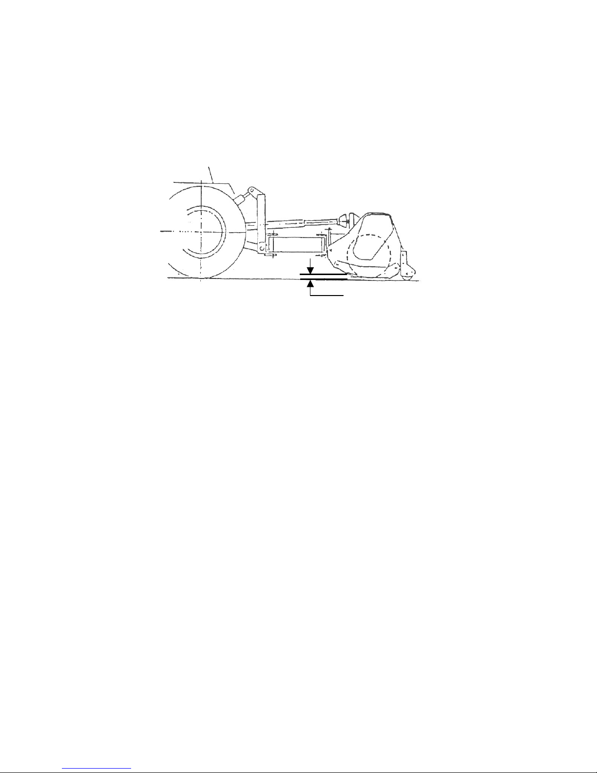
5. ADJUSTMENT AND SETTING UP
5.1 Adjustment
Adjustment of the height of cut is obtained by shifting the flail head roller in order to
suit the material to be cut and the required degree of chopping (see illustration
below).
IMPORTANT: Flails must never touch the ground.
6. USE AND OPERATING RULES
6.1 Starting
Before using the shredder check the tightness of all bolts and the integrity of all
guards. Check that the number of revolutions and the rotational direction of the
power takeoff of the tractor correspond to those required by the machine see decal on
the gearbox (see page 9). Engage the power takeoff at low engine RPM to avoid
damaging the transmission gearbox and belts.
6.2 Working mode
• Adjust the machine to suit the type of work to be done and the material to be cut:
adjust the height of cut, as shown (see illustration above).
• Working speed is chosen to suit the material to be cut and the degree of chopping
required. The optimum speed ranges from 3 to 8 km per hour.
6.3 Side shift - Non-hydraulic models
IMPORTANT: if you want to move the machine from the central to side position
proceed as follows:
• Unscrew the connecting bow.
• Bore the holes on marked points. (upper cover already has got the holes).
• Put the connecting bow on the new position.
• Tighten the screws.

13
6.4 Side shift – Hydraulic models
IMPORTANT: Ensure that the machine is lifted clear of the ground before side
moving, failure to observe this may result in damage to the frame.
IMPORTANT: During reverse movement lift the machine off the ground to
avoid damaging the machine.
6.5 Stopping
• Close the arms and lower the machine to the ground.
• Disconnect the power takeoff.
• Stop the tractor, take out the starting key and apply the hand brake.
• If the ground is sloping, block the tractor wheels.
6.6 Transport position
For transport it is mandatory to:
• Observe all road transport requirements and note the necessary warning signs.
• Reduce speed especially on bumpy roads, The weight of the machine may render
driving difficult and damage the machine itself.
• The power take off must be disconnected.
IMPORTANT: during transport on bumpy roads it is mandatory to move the
machine into the central position.

14
7. MACHINE MAINTENANCE
All maintenance, cleaning and repair operations must be carried out with the shredder
firmly lowered to the ground and detached from the tractor, or with disconnected
PTO, and the tractor engine switched off and starting key out.
After the first two hours operation from new (or after fitting new belts) check belt
tension.
Regularly and after every 8 hours of machine operation:
• Tighten bolts and nuts.
• Check wear and condition of flails.
• Check the safety guards.
• Check belt condition.
• Visually check the frame to detect possible damage caused by earlier work.
• Check gearbox and extension lubricating levels.
• Grease the parts indicated on the appropriate decal. (see below).
This operation must be always carried out at the end of each working day. This
facilitates the removal of mud or other material from the rotating parts (bearing, pins
etc.) in order to avoid rust and possible seizure.
• Every 100 hours operation grease the moving parts of the PTO shaft, extracting
the two parts of the shaft.
• After long inactivity, repeat the operation before re-using the machine.
• Use grease classification DIN 51825 (KR 2 K)
• For gearbox use compatible oils - classification ISO VG 220
Oil level point
Oil level point
15
PROBLEM CAUSES REMEDIES
Irregular cut - Worn, bent or broken flails. -Replace.
-Machine is not in level with the -Level.
ground. -Reduce working speed.
Clogged material due to
excessive working speed.
Machine noise - Loose bolts. -Tighten bolts.
-Cracks or initiation of flail head. -Have it repeared in
specialized workshops.
Gearbox noise - Lack of oil. -Fill to level.
-Worn gears. -Replace.
-Worn bearings. -Replace.
Vibration - Broken or worn flails. -Replace.
-Unbalanced rotor. -Replace in authorized
-Worn rotor bearings. workshops.
Premature flail wear - Flails touching the ground. -Adjust the height of cut.
Excessive backlash - Worn pins. -Replace.
in joints
Breakage of roller - Violent impact on the ground -Lower it gently.
bearings when the machine is lowered. -Clean and grease.
-Dirty or little greased bearings.
Belts overheating - Flails touching to the ground. -Adjust the height of cut.
-Working speed unsuitable to the -Reduce speed.
amount of the material to be cut.
8. TROUBLE SHOOTING CHART
9. REPLACING PARTS
Before carrying out any work, it is mandatory to:
• Lower the machine to the ground
• Disconnect the power takeoff, stop the tractor and take out the starting key.
• Wear working gloves
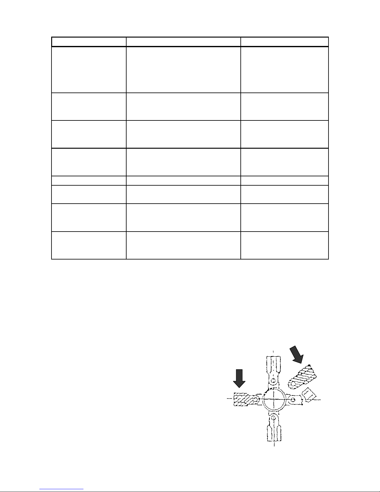
9.1 Flail replacement
When the flails are worn, they must all be replaced.
In cases of a partially broken flail it is advisable to
replace the broken one and the one diametrically
opposite, in order to maintain the balance
(see illustration opposite).

16
9.2 Belt replacement
• This operation must be carried out with the machine touching the ground, the
power take-off disconnected and the starting key out.
• Remove the belt guard, slacken the screws (1) (see diagram below), unscrew the
tightener (2), remove the belts and replace them with the same ones (dimension
and type).
IMPORTANT: more complex operations must be done in authorised workshops.
10. DEMOLITION, DIFFERENTIATED DIVISION OF THE MATERIALS
AND DISPOSAL
If the machine is out of order and requires disposal, all its parts that may cause danger
have to be made inoffensive. The materials forming the machine that have to undergo
a differentiated division are:
• Steel
• Mineral oil
• Rubber
• Plastic
All the above mentioned operations and the disposal have to be carried out in total
respect of the present provisions of law on the subject.
We reserve right to modify the technical data and characteristics of the machines at
any time without prior notice.

17
SPARE PARTS SECTION
For best performance…
USE ONLY GENUINE SERVICE PARTS
To be assured of the latest desi
g
n improvements purchase
y
our ‘Genuine
R
eplacements’
f
rom the Ori
g
inal Equipment Manu
f
acturer throu
g
h
y
ou
r
local Dealer or Stockist.
Always quote:
• Machine Type
• Serial Number
• Part Number
D
esi
g
n Improvements ma
y
have altered some o
f
the parts
l
isted in this
manual – The latest part will alwa
y
s be supplied when it is interchan
g
eable
with an earlier one.
Other manuals for MAGNUM 130
1
This manual suits for next models
3
Table of contents
Other McConnel Lawn Mower manuals

McConnel
McConnel ECON HEDGEMASTER Mk3 User manual

McConnel
McConnel MAGNUM MULCHA 225 User manual

McConnel
McConnel SR15-6 User manual

McConnel
McConnel MERLIN Xtreme Offset Programming manual

McConnel
McConnel PA5054 VERSI User manual

McConnel
McConnel ROBOMAX User manual

McConnel
McConnel Twose Series User manual

McConnel
McConnel MAGNUM HEAVY DUTY Series User manual

McConnel
McConnel ROBOCUT RC28 User manual

McConnel
McConnel PA5040-40 User manual


