McConnel RoboCut Programming manual

Publication 679
August 2011
Part No. 22674.79
Revision: 30.06.17
McCONNEL
ROBOCUT
REMOTE CONTROLLED MOWER
Operator & Parts Manual
Machines from 07-13 / Serial No. 011400323 ►

IMPORTANT
VERIFICATION OF WARRANTY REGISTRATION
DEALER WARRANTY INFORMATION & REGISTRATION VERIFICATION
It is imperative that the selling dealer registers this machine with McConnel Limited before
delivery to the end user – failure to do so may affect the validity of the machine warranty.
To register machines go to the McConnel Limited web site at www.mcconnel.com, log
onto ‘Dealer Inside’ and select the ‘Machine Registration button’which can be found in
the Service Section of the site. Confirm to the customer that the machine has been
registered in the section below.
Should you experience any problems registering a machine in this manner please contact
the McConnel Service Department on 01584 875848.
Registration Verification
Dealer Name:
……………………..…………………………………………………………….
Dealer Address:
…….………………………………………………………………………….
Customer Name:
……………………..…………………………………………………………
Date of Warranty Registration:
……/……/...…… Dealer Signature: ………………..……
NOTE TO CUSTOMER / OWNER
Please ensure that the above section above has been completed and signed by the selling
dealer to verify that your machine has been registered with McConnel Limited.
IMPORTANT: During the initial ‘bedding in’ period of a new machine it is the customer’s responsibility
to regularly inspect all nuts, bolts and hose connections for tightness and re-tighten if required. New
hydraulic connections occasionally weep small amounts of oil as the seals and joints settle in – where
this occurs it can be cured by re-tightening the connection – refer to torque settings chart below.The
tasks stated above should be performed on an hourly basis during the first day of work and at least
daily thereafter as part of the machines general maintenance procedure.
CAUTION: DO NOT OVER TORQUE HYDRAULIC FITTINGS AND HOSES
TORQUE SETTINGS FOR HYDRAULIC FITTINGS
HYDRAULIC HOSE ENDS PORT ADAPTORS WITH BONDED SEALS
BSP
Setting
Metric
BSP
Setting
Metric
1/4” 18 Nm 19 mm 1/4” 34 Nm
19 mm
3/8” 31 Nm 22 mm 3/8” 47 Nm
22 mm
1/2” 49 Nm 27 mm 1/2” 102 Nm
27 mm
5/8” 60 Nm 30 mm 5/8” 122 Nm
30 mm
3/4” 80 Nm 32 mm 3/4” 149 Nm
32 mm
1” 125 Nm 41 mm 1” 203 Nm
41 mm
1.1/4”
190 Nm
50 mm
1.1/4”
305 Nm
50 mm
1.1/2” 250 Nm 55 mm 1.1/2” 305 Nm
55 mm
2” 420 Nm 70 mm 2” 400 Nm
70 mm

WARRANTY POLICY
WARRANTY REGISTRATION
All machines must be registered, by the selling dealer with McConnel Ltd, before delivery to the
end user. On receipt of the goods it is the buyer’s responsibility to check that the Verification of
Warranty Registration in the Operator’s Manual has been completed by the selling dealer.
1. LIMITED WARRANTIES
1.01. All machines supplied by McConnel Ltd are warranted to be free from defects in material and
workmanship from the date of sale to the original purchaser for a period of 12 months, unless
a different period is specified.
1.02. All spare parts supplied by McConnel Ltd and purchased by the end user are warranted to be
free from defects in material and workmanship from the date of sale to the original purchaser
for a period of 6 months. All parts warranty claims must be supported by a copy of the failed
part invoice to the end user. We cannot consider claims for which sales invoices are not
available.
1.03. The warranty offered by McConnel Ltd is limited to the making good by repair or replacement
for the purchaser any part or parts found, upon examination at its factory, to be defective
under normal use and service due to defects in material or workmanship. Returned parts
must be complete and unexamined. Pack the component(s) carefully so that any transit
damage is avoided. All ports on hydraulic items should be drained of oil and securely plugged
to prevent seepage and foreign body ingress. Certain other components, electrical items for
example, may require particular care when packing to avoid damage in transit.
1.04. This warranty does not extend to any product from which McConnel Ltd’s serial number plate
has been removed or altered.
1.05. This warranty does not apply to any part of the goods, which has been subjected to improper
or abnormal use, negligence, alteration, modification, fitment of non-genuine parts, accident
damage, or damage resulting from contact with overhead power lines, damage caused by
foreign objects (e.g. stones, iron, material other than vegetation), failure due to lack of
maintenance, use of incorrect oil or lubricants, contamination of the oil, or which has served
its normal life. This warranty does not apply to any expendable items such as blades, belts,
clutch linings, filter elements, flails, flap kits, skids, soil engaging parts, shields, guards, wear
pads, pneumatic tyres or tracks.
1.06. Temporary repairs and consequential loss - i.e. oil, downtime and associated parts are
specifically excluded from the warranty.
1.07. Warranty on hoses is limited to 12 months and does not include hoses which have suffered
external damage. Only complete hoses may be returned under warranty, any which have
been cut or repaired will be rejected.
1.08. Machines must be repaired immediately a problem arises. Continued use of the machine
after a problem has occurred can result in further component failures, for which McConnel Ltd
cannot be held liable, and may have safety implications.
1.09. If in exceptional circumstances a non McConnel Ltd part is used to effect a repair, warranty
reimbursement will be at no more than McConnel Ltd’s standard dealer cost for the genuine
part.
1.10. Except as provided herein, no employee, agent, dealer or other person is authorised to give
any warranties of any nature on behalf of McConnel Ltd.
1.11. For machine warranty periods in excess of 12 months the following additional exclusions
shall apply:
1.11.1. Hoses, exposed pipes and hydraulic tank breathers.
1.11.2. Filters.
1.11.3. Rubber mountings.
1.11.4. External electric wiring.
1.11.5. Bearings and seals.

1.12. All service work, particularly filter changes, must be carried out in accordance with the
manufacturer’s service schedule. Failure to comply will invalidate the warranty. In the event of
a claim, proof of the service work being carried out may be required.
1.13. Repeat or additional repairs resulting from incorrect diagnosis or poor quality previous repair
work are excluded from warranty.
NB Warranty cover will be invalid if any non-genuine parts have been fitted or used. Use of non-
genuine parts may seriously affect the machine’s performance and safety. McConnel Ltd cannot be
held responsible for any failures or safety implications that arise due to the use of non-genuine parts.
2. REMEDIES AND PROCEDURES
2.01. The warranty is not effective unless the Selling Dealer registers the machine, via the
McConnel Ltd web site and confirms the registration to the purchaser by completing the
confirmation form in the operator’s manual.
2.02. Any fault must be reported to an authorised McConnel Ltd dealer as soon as it occurs.
Continued use of a machine, after a fault has occurred, can result in further component
failure for which McConnel Ltd cannot be held liable.
2.03. Repairs should be undertaken within two days of the failure. Claims submitted for repairs
undertaken more than 2 weeks after a failure has occurred, or 2 days after the parts were
supplied will be rejected, unless the delay has been authorised by McConnel Ltd. Please
note that failure by the customer to release the machine for repair will not be accepted as a
reason for delay in repair or submitting warranty claims.
2.04. All claims must be submitted, by an authorised McConnel Ltd Service Dealer, within 30 days
of the date of repair.
2.05. Following examination of the claim and parts, McConnel Ltd will pay, at their discretion, for
any valid claim the invoiced cost of any parts supplied by McConnel Ltd and appropriate
labour and mileage allowances if applicable.
2.06. The submission of a claim is not a guarantee of payment.
2.07. Any decision reached by McConnel Ltd is final.
3. LIMITATION OF LIABILITY
3.01. McConnel Ltd disclaims any express (except as set forth herein) and implied warranties with
respect to the goods including, but not limited to, merchantability and fitness for a particular
purpose.
3.02. McConnel Ltd makes no warranty as to the design, capability, capacity or suitability for use of
the goods.
3.03. Except as provided herein, McConnel Ltd shall have no liability or responsibility to the
purchaser or any other person or entity with respect to any liability, loss, or damage caused
or alleged to be caused directly or indirectly by the goods including, but not limited to, any
indirect, special, consequential, or incidental damages resulting from the use or operation of
the goods or any breach of this warranty. Notwithstanding the above limitations and
warranties, the manufacturer’s liability hereunder for damages incurred by the purchaser or
others shall not exceed the price of the goods.
3.04. No action arising out of any claimed breach of this warranty or transactions under this
warranty may be brought more than one (1) year after the cause of the action has occurred.
4. MISCELLANEOUS
4.01. McConnel Ltd may waive compliance with any of the terms of this limited warranty, but no
waiver of any terms shall be deemed to be a waiver of any other term.
4.02. If any provision of this limited warranty shall violate any applicable law and is held to be
unenforceable, then the invalidity of such provision shall not invalidate any other provisions
herein.
4.03. Applicable law may provide rights and benefits to the purchaser in addition to those provided
herein.

DECLARATION OF CONFORMITY
Conforming to EU Machinery Directive 2006/42/EC
We,
McCONNEL LIMITED, Temeside Works, Ludlow, Shropshire SY8 1JL, UK
Hereby declare that:
The Product; Radio Controlled Tracked Mower
Product Code; RMOW
Serial No. & Date ………………………………… Type …………………………
Manufactured in; Italy
Complies with the required provisions of the Machinery Directive 2006/42/EC
The machinery directive is supported by the following harmonized standards;
BS EN ISO 12100 (2010) Safety of machinery – General principles for design – Risk
assessment and risk reduction.
BS EN 349 (1993) + A1 (2008) Safety of machinery - Minimum distances to avoid the
entrapment with human body parts.
BS EN 953 (1997) + A1 (2009) Safety of machinery - Guards general requirements for
the design and construction of fixed and movable guards.
BS EN 4413 (2010) Hydraulic fluid power. Safety requirements for systems and their
components.
McCONNEL LIMITED operates an ISO 9001:2008 quality management system,
certificate number: FM25970.
This system is continually assessed by the;
British Standards Institution (BSI), Beech House, Milton Keynes, MK14 6ES, UK
BSI is accredited by UK Accreditation Service, accreditation number: UKAS 003.
The EC declaration only applies if the machine stated above is used in
accordance with the operating instructions.
Signed …………………................ Responsible Person
CHRISTIAN DAVIES on behalf of McCONNEL LIMITED
Status: General Manager Date: September 2015

For Safety and Performance…
ALWAYS READ THIS BOOK FIRST
McCONNEL LIMITED
Temeside Works
Ludlow
Shropshire
England
Telephone: 01584 873131
www.mcconnel.com


LIST OF CONTENTS
Page No.
Operator Section
General Information 1
Features & Specifications 2
Safety Information 3
Safety Decals & Warnings 6
Safety Devices & Emergency Stop 7
Machine Delivery 8
Machine Overview 9
Display LCD 11
Radio Control Unit 15
Starting the Engine 16
Driving & Manoeuvring 17
Emergency Manual Control Unit 22
Pre-Operation Checks 24
Operation 25
Operating Position & Distance 27
Maintenance 28
Undercarriage Specifications 40
Electrical System Fuses & Relays 41
Troubleshooting 42
Parts Section
Chassis Assembly 2
Track Roller Assemblies 4
Track Tensioner Assemblies 6
Rubber Tracks 8
Equipment Mounting Assembly 10
Engine Cover Assembly 12
Radiator Cover Assembly 14
Machine Cover Assembly 16
Roll bar Assembly 18
Diesel Engine 20
Diesel Engine Components 24
Pumps Assembly (Early Machines) 26
Pumps Assembly (Current Machines) 28
Actuator Assembly 30
Reversible Fan Assemblies 32
Diesel Fuel Circuit 38
Oil Tank Assembly 40
Electrical Components 42
Electrical Wiring 46
Control Transmitting / Receiving Units 48
Intake & Drain Pumps 50
Tracks Hydraulic Circuit 52
Hydraulic Rams Circuit 54
Hydraulic Equipment Circuit 56
Flailhead Assembly 58
Rotors & Flails 66
Flailhead Hydraulic Assembly 70
Decal Kit 74
Service Parts 75


1
GENERAL INFORMATION
Always read this manual before attempting to operate the machine – whenever any doubt exists
contact your dealer or the McConnel Service Department for advice and assistance.
Use only McConnel Genuine Service Parts on McConnel Equipment and Machines
DEFINITIONS –The following definitions apply throughout this manual:
WARNING
An operating procedure, technique etc., which –
can result in personal injury or loss of life if not observed carefully.
CAUTION
An operating procedure, technique etc., which –
can result in damage to either machine or equipment if not observed carefully.
NOTE
An operating procedure, technique etc., which is –
considered essential to emphasis.
LEFT AND RIGHT HAND
These terms are applicable to the machine when it is viewed from the rear facing forwards.
Note: The illustrations in this manual are for instructional purposes only and may on occasion not show
some components in their entirety. In some instances an illustration may appear slightly different to that of
your particular model but the general procedure will be the same. E&OA.
MACHINE & DEALER INFORMATION
Record the Serial Number of your machine on this page and always quote this number when
ordering parts. Whenever information concerning the machine is requested remember also
to state the make and model of tractor to which the machine is fitted.
Machine Serial Number: Installation Date:
Machine Model details:
Dealer Name:
Dealer Address:
Dealer Telephone No:
Dealer Email Address:

2
FEATURES & SPECIFICATIONS
RoboCut
○40HP (29kW) 3 Cylinder ISUZU Diesel Engine
○Tracked Carriage Hydraulically Driven via Piston Pumps
○Self-Tightening Tracks
○Remote Controlled Operation (up to 150m range)
○Rubber Tracks with Removable Riveted Stirrups
○Rubber Stopper Spike Protection for Transport
○Potentiometer Speed Control from 0 to 100%
○Independent Cooling System for Hydraulic Circuits
○Self-Cleaning Reversible Fan
○Electronically Controlled, Hydraulically Powered Flail Head
○Proportional Joystick Speed Control – Forwards & Backwards 0 to 7km/h
○21 Litre Fuel Tank Capacity
○1280mm Carriage Width
○1.3m Flail Head capable of cutting materials up to 30mm diameter
○Machine Weight 1000kg

3
SAFETY INFORMATION
This machine has the potential to be extremely dangerous - in the wrong hands it can kill or
maim; It is therefore imperative that both owner and operator of the machine reads and
understands the following section to ensure they are fully aware of the dangers that do, or may
exist, and their responsibilities surrounding the use and operation of the machine.
The operator of this machine is responsible not only for their own safety but equally for the
safety of others who may come into the close proximity of the machine, as the owner you are
responsible for both.
When the machine is not in use it should be parked on a firm level site with the cutting head
resting on the ground and the starting key removed.
In the event of any fault being detected with the machine’s operation it must be stopped
immediately and not used again until the fault has been corrected by a qualified technician.
Before starting the machine the operator must read and understand all aspects of use and
maintenance of the machine as stated in this manual.
The machine must only be used by a responsible adult who is familiar with all aspects
relating to safe operation.
The machine must not be operated by children or non-authorised persons.
Operators must know the meaning of all operation and safety decals on both the machine
and the remote control unit.
Operators must know the procedure for switching the machine off normally and the correct
procedure for using the Emergency Stop.
Do not attempt to use the machine if the Emergency Stop switch is damaged or
malfunctioning.
Never use the machine with safety guarding removed or defective.

4
Operators should practice operation on flat open ground to familiarise themselves with
driving and manoeuvring the machine before attempting to use it on sloping ground.
Operators should practice manoeuvring the machine around obstacles without the flail head
running before using the machine for work purposes.
Never operate the machine when your vision is blocked by obstacles such as vehicles,
buildings, hedges etc.; move to a position where you have an un-interrupted view of the
machine.
Never operate the machine standing directly in the line of travel.
Do not use the machine on sand piles, gravel, or similar materials.
Only operate the machine in good light conditions.
Never run the machine in an enclosed area or building.
Keep the machine clean to avoid build ups of dry materials that could ignite on hot
components.
Never stand directly below a machine that is operating or parked on a slope.
Always operate the joystick control slowly; rapid or jerky movements can cause the machine
to rear up causing loss of control.
When operating the machine with the flail head running the operator must remain at least 5
metres away from the machine; always switch the flail head off before approaching it.
When using the machine the operator should place themselves in a position that provides
optimum visibility over the work area.
Never leave a running machine unattended; always switch the engine off and remove the
ignition key.
Always stop and switch the machine off if persons or animals enter the work area, do not
restart the machine until they are at a safe distance.
Never use the machine to perform tasks it was not designed for.
Never ride, or allow others to ride on the machine.
Always inspect the work area prior to operation and remove stones, glass, metal, wire or any
other foreign objects that are hazardous. Immovable hazards should be ‘marked’ so they
can be avoided.
Take extra care when operating the machine on slopes or uneven ground, there is increased
risk of objects being thrown from the flail head when working in these conditions.
The machine can be used on slopes up to a maximum of 55° (track option dependant)
providing the surface is dry and firm.

5
Should a machine overturn, a suitable crane or winch should be used to recover it, keep all
persons at a safe distance before and during recovery.
Do not operate the machine in foggy or frosty conditions as there is increased risk of
accidents.
Take extra care when working in close proximity to electrical cables; in some circumstances,
operating the machine under overhead power lines can result in loss of radio signal causing
the engine to deactivate.
Do not operate the machine close to vehicles or properties where there is risk of damage by
objects accidentally thrown from the flail head.
It is the user’s responsibility to protect persons in or near the work zone.
When servicing or maintaining the machine no one should be allowed beneath it when it is
raised unless it is securely supported on suitable ramps or stands.
Never attempt to service or maintain the machine whilst it is running; always switch off the
engine and remove the starting key.
When transporting the machine on another vehicle or trailer the engine must be switched off
and the machine chocked and secured using suitable ropes or chains.
Check the condition of the flails and fixings on a regular basis; never use the machine with
damaged/missing flails or loose fixings.
Always clean the machine after use; care must be taken if the machine is hot. Never use
solvent based chemicals for cleaning.
When operating in excessively dusty conditions work may need to be interrupted on a
regular basis to remove any build ups of dust on components that could cause overheating.
Ensure engine is switched off and Emergency Stop switch is in the ‘off’ position before
refuelling.
Wherever possible refuel the machine before work when the engine is cold. If refuelling
during work, switch off the engine and allow it to cool before adding fuel.
Test the Emergency Stop switch before each period of work to ensure it functions correctly.
Never leave the machine, ignition key and control unit unattended where it could be started
and used by un-authorised persons.
Any inspection, service or maintenance of the flail head must only be performed with
machine switched off and the starting key removed.
Always wear safety gloves and glasses when performing service or maintenance on the flail
head.
Flail head must always be switched off when manoeuvring outside of the work zone.

6
SAFETY & WARNING DECALS
1. WARNING: Read the manual first.
2. DANGER: Risk of thrown objects, keep your distance.
3. DANGER: Electrical voltage and harmful substances.
4. DANGER: Acid, read the user and maintenance manual.
5. DANGER: Rotating components, keep clear.
6. DANGER: Hot components, risk of burns.
7. WARNING: Do not lubricate or service moving components, stop the machine first.
8. ADVISORY: Always wear ear defenders and safety glasses when using the machine.
9. ADVISORY: Always wear safety footwear when using the machine.

7
SAFETY DEVICES & EMERGENCY STOP
Automatic Emergency Safety Features
As the RoboCut is operated by remote control and the user is not directly operating the driving
elements of the machine specific safety features have been built in to protect the user, third
party persons and the machine itself; these are as follows
Danger / Risk Situation Automatic Safety Feature
Machine beyond signal reception area or radio signal blocked. EMERGENCY STOP will activate.
Radio signal failure. EMERGENCY STOP will activate.
Another machine on same frequency operating in the area. EMERGENCY STOP will activate.
Manual Emergency Safety Feature
In addition to the automatic safety features stated above the operator can immediately stop
machine movements / operations either by pressing the Emergency Stop button located on the
remote control unit or by pressing the Emergency Stop button located on the top panel of the
machine itself.
In all instances stated above, emergency stopping of the machine will take a maximum of 0.2
seconds from execution of the automatic or manual command and the following actions will
occur;
Machines to June 2015;
Machine movement / operations and functions will be halted.
Electrical voltage will be deactivated.
Entire electrical system will be disabled.
Engine will be switched off
Ignition will be turned off.
Machines June 2015 onward;
Machine movement / operations and functions will be halted.
Engine will remain running (Engine RPM is automatically reduced to idle speed).
Note; after using Emergency Stop the machine will cease to function completely, to regain
functions and continue operating the Connection/Horn button on the Remote Control Unit must
be operated or the engine manually switched off and a normal restart performed.
In the unlikely event of movement malfunction
If machine movements perform in an unexpected or incorrect manner follow the instructions
below;
1) Release the forwards/backwards movement joystick – the control is equipped with automatic
zero position; on release it will automatically return to the central (stop) position, this action
activates the track brakes.
2) Press the Emergency Stop button on the control unit.
DANGER! Do not approach the machine if it is moving.
3) Press the machine’s Emergency Stop button.
4) Turn the ignition key into the off position (anti-clockwise) and remove the key.
Contact your Authorised Dealer or McConnel Service – do not attempt to operate the
machine until advice has been sought.

8
MACHINE DELIVERY
The machine will be delivered ready for use having been pre-filled with all necessary lubricants
and fluids other than fuel.
Before use all packaging must be removed and the transport fasteners loosened.
The reception antenna will be supplied as a loose item and must be screwed onto the machines
receiver prior to use.
The standard items supplied will be as follows:
Standard Equipment
Machine with Mounted Receiver
Transmitter and Battery Pack
Reserve Battery Pack
Battery Charger 12V CA
Antenna
Belt for the Radio Control
Ignition Key
Use and Maintenance Manual for Machine
Use and Maintenance Manual for Transmitter
Use and Maintenance Manual for Engine
Machine Lifting Points
The photos below shown the machine’s lifting points; the lifting eyes are located at each end of
the track plates on both sides of the machine. The positions of the lifting points enable the
machine to be safely raised using suitable overhead lifting equipment.
Note: All equipment used to raise the machine must have a SWL in excess of the total weight of the
machine – keep all persons at a safe distance from the machine during the lifting procedure.

9
MACHINE OVERVIEW – Component Identification
◄Right Side View
1. Oil Tank
2. Diesel Fuel Tank
3. Track Tensioner Access
4. Track Roller
5. Drive Wheel
6. Alternator (12V)
Left Side View ►
1. Hydraulic Motor
2. Electrics
3. Warning Beacon Mount
4. Water / Oil Radiator
5. Conveyor & Radiator Guard
6. Rubber Tracks
7. Electric Actuator
8. Track Tensioner Access
9. Lubrication Point
10. Hydraulic Ram (Front Hood)
◄Engine Top View
1. Air Filter Clogging Sensor
2. Radio Control Antenna
3. Warning Beacon Mount
4. Engine Oil Filler Plug
5. Air Filter
6. Air Filter Breather

10
Engine Right Side View ►
1. Radiator Filler
2. Radio Control Antenna
3. Warning Beacon Mount
4. Emergency Stop Switch
5. Electric Plug for Services (12V)
6. Horn
7. Electric Compressor
(Self-Cleaning Radiator Fan)
8. Ant-vibration Engine Support
9. Exhaust Pipe
10. Alternator (12V)
11. Air Filter
◄Engine Left Side View
1. Emergency Stop Switch
2. Warning Beacon Mount
3. Air Filter
4. Radiator Fan Guard
5. Radiator Filler
6. Oil Cooler Input
7. Oil Cooler Output
8. Engine Oil Filler Plug
9. Secondary Fuel Filter
10. Electric Actuator
11. Electric Pump
12. Temperature Gauge
(Engine Coolant)
13. Ignition Key

11
Ignition Panel Components
1. Display LCD
2. Ignition Switch
3. Emergency Stop Switch
Display LCD (CANBUS)
1. Alternator
2. Engine Oil Low Pressure
3. Pre-heater (optional feature)
4. Engine Stop
5. Service
6. Parking Brake
7. Water Temperature
8. Page Up
9. Page Down
10. Enter
11. Home Page (Screen)
Other manuals for RoboCut
1
Table of contents
Other McConnel Lawn Mower manuals
McConnel
McConnel RoboCut Programming manual
McConnel
McConnel MERLIN Xtreme Offset Programming manual

McConnel
McConnel Twose Series User manual
McConnel
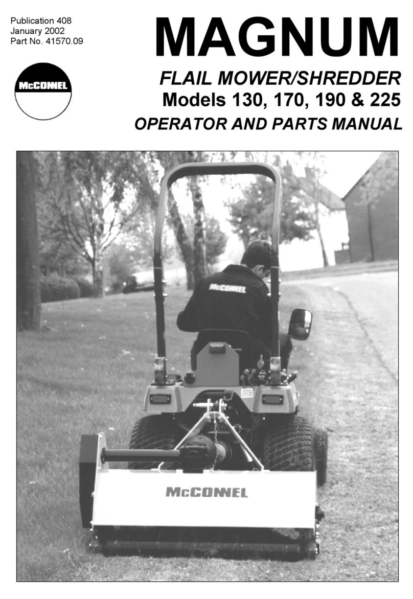
McConnel MAGNUM 130 Product manual

McConnel
McConnel ROBOMAX User manual

McConnel
McConnel ROBOCUT RC28 User manual

McConnel
McConnel SR420 User manual
McConnel
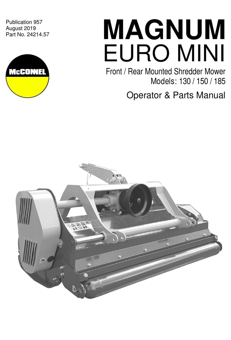
McConnel MAGNUM EURO MINI Series Programming manual
McConnel
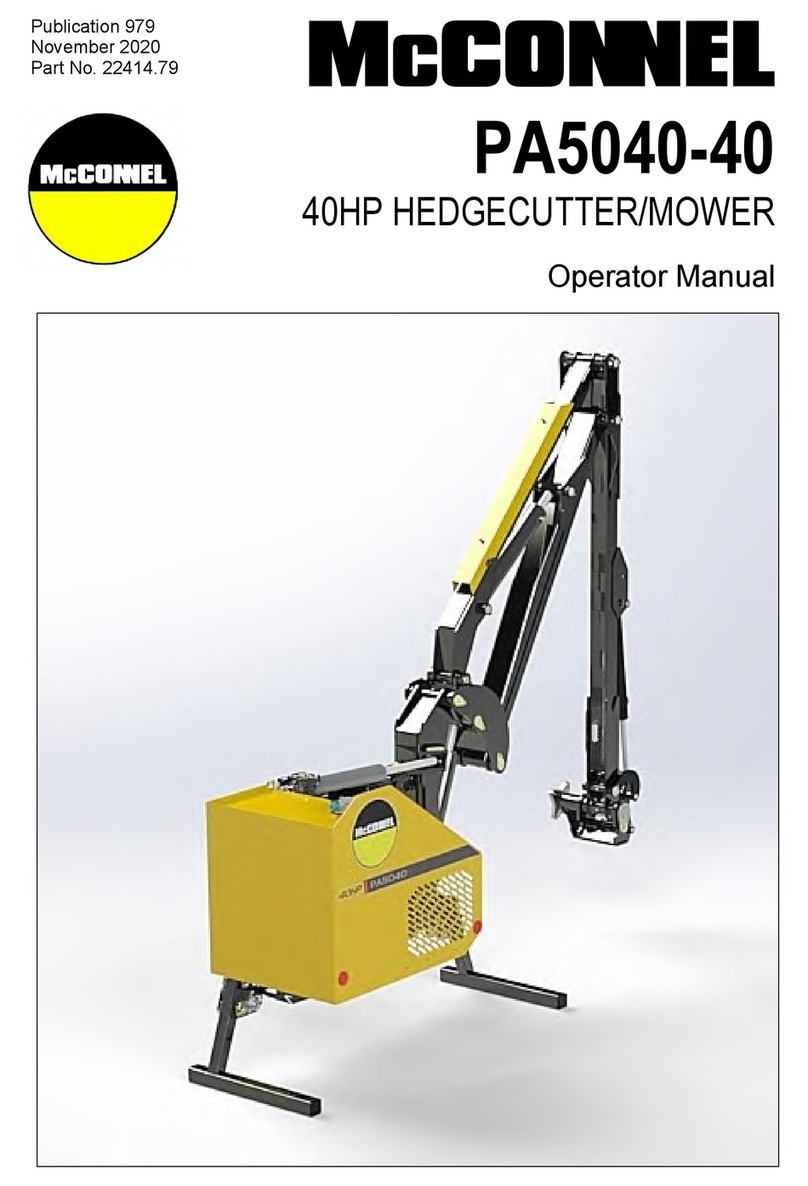
McConnel PA5040-40 User manual

McConnel
McConnel MAGNUM MULCHA 225 User manual

