ISCO Fusion Manual
34
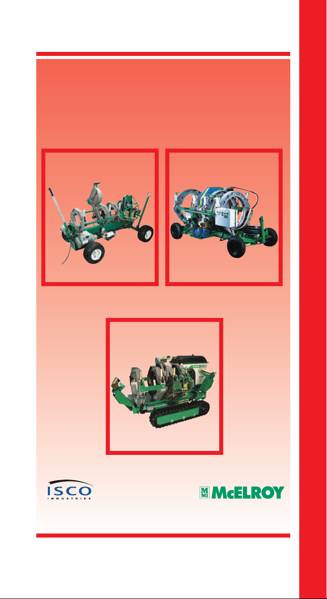
Hydraulic Butt Fusion Machine Procedure
© Copyright 2007 ISCO Industries, LLC All rights reserved.
Hydraulic Butt Fusion Machine Procedure
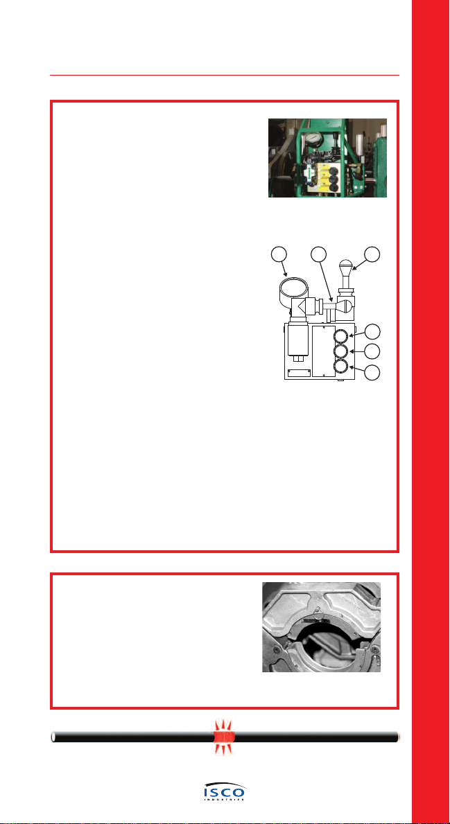
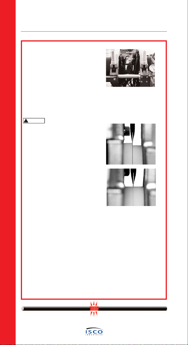
Check Hydraulic Pressure
The pressure gauge on the manifold block indicates the pressure of the
carriage valve. How much pressure depends on the position of the selec-
tor valve and the pressure set on the specific pressure reducing valve.
With the selector valve up, the facing pressure can be set. It may be nec-
essary to adjust the carriage speed, while facing, with the top pressure-
reducing valve to control facing speed.
Shift the selector valve to the center position, heating, and set the pres-
sure reducing valve at its lowest setting, or the drag pressure, whichever is
higher.
With the selector valve in the down position, the fusion pressure can be
set.
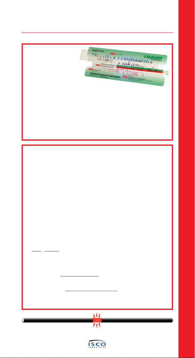
The fusion pressure can be calculated using the Fusion Pressure
Calculator (shown on the next page or by using the formula on the next
page, or they can be found in the reference section.)
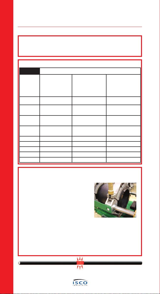
An approximate 2 Bar (30 psi) drag factor should compensate for seal, and
pipe drag with one joint of pipe on a pipe stand. If additional lengths of
pipe are being moved by the movable jaws, the actual drag pressure should
be determined using the following procedure:
After facing the pipe, move the carriage so that the pipe ends are
approximately 50 mm (2") apart.
Shift the carriage control valve to the middle (neutral) position, select
the heating mode, and adjust the middle pressure reducing valve to its
lowest pressure by turning the valve counterclockwise.
Shift the carriage control valve to the left.
Gradually increase the pressure by turning the heating valve clockwise.
Increase the pressure until the carriage moves.
Quickly reduce the heating pressure valve counterclockwise until the
carriage is just barely moving.
Record this actual drag pressure.
Take the pressure, determined from the Fusion Pressure Calculator, and
add the actual measured drag pressure. This will be the actual fusion
pressure to set with the bottom pressure reducing valve. If fusion pres-
sures are used from the reference section, you must subtract 2 Bar (30
psi) drag, which is already figured in and then add the actual drag
pressure back.
Adjust the middle heating valve to show recorded drag so that pipe ends
will stay in contact with heater during heating phase.