TECNA T-SPOT 110 User manual

IT
Art. 3540 T-SPOT 110 – SPOTTER MULTIFUNZIONE PORTATILE, 2,5 kVA
EN
Item 3540 T-SPOT 110 – PORTABLE MULTIFUNCTION SPOTTER, 2.5 kVA
FR
Réf. 3540 T-SPOT 110 – SPOTTER MULTI-FONCTION PORTABLE, 2,5 kVA
DE
Art. 3540 T-SPOT 110 – TRAGBARER SPOTTER-MULTIFUNKTION, 2,5 kVA
ES
Art. 3540 T-SPOT 110 – SPOTTER MULTIFUNCIÓN PORTÁTIL, 2,5 kVA
TECNA S.p.A. - Via Meucci 27 - 40024 Castel S. Pietro Terme - Bologna (Italia)
Pho. +39-051-6954400 - Tel. +39-051-6954410 - Fax +39-051-6954490 - http://www.tecna.net
DOCUMENTO NUMERO:
DOCUMENT NUMBER:
DOCUMENT NUMERO:
DOKUMENT NUMMER:
DOCUMENTO:
MAN 2032
EDIZIONE:
EDITION:
EDITION:
AUFLAGE:
EDICION:
01 / 2013

2
IT
SOMMARIO
INTRODUZIONE................................................................................................................................ 3
SIMBOLOGIA UTILIZZATA................................................................................................................ 3
IDENTIFICAZIONE PARTI PRINCIPALI DELLA SALDATRICE ........................................................ 4
DOTAZIONE DI SERIE...................................................................................................................... 4
CARATTERISTICHE TECNICHE....................................................................................................... 4
DESCRIZIONE GENERALE.............................................................................................................. 5
INSTALLAZIONE............................................................................................................................... 5
INSTALLAZIONE ELETTRICA........................................................................................................... 5
INSTALLAZIONE CARRELLO OPZIONALE...................................................................................... 5
MESSA IN FUNZIONE....................................................................................................................... 6
NORME DI SICUREZZA.................................................................................................................... 6
PROGRAMMAZIONE........................................................................................................................ 7
PISTOLA MULTIFUNZIONE ............................................................................................................. 8
RADDRIZZATURA DI DEFORMAZIONI RILEVANTI SU LAMIERATI DELLA CARROZZERIA........ 8
RICALCATURA.................................................................................................................................. 9
RISCALDAMENTI LOCALIZZATI CON ELETTRODO DI CARBONE................................................ 9
SALDATURA DI RIVETTI .................................................................................................................. 9
FUNZIONE DI CONTROLLO SALDATURA INTERROTTA............................................................... 9
MANUTENZIONE ............................................................................................................................ 10
MANUTENZIONE ORDINARIA........................................................................................................ 10
MANUTENZIONE STRAORDINARIA .............................................................................................. 10

3
INTRODUZIONE
LEGGERE ATTENTAMENTE QUESTO MANUALE
DI ISTRUZIONE PRIMA DI INSTALLARE ED
UTILIZZARE LA SALDATRICE
Scopo di questo manuale, e dei documenti allegati, è la
trasmissione delle informazioni necessarie all’uso competente e
sicuro del prodotto. Esso comprende informazioni inerenti la
sicurezza, l’installazione, l’uso, la manutenzione e lo smaltimento
del prodotto. Il presente manuale è indirizzato al responsabile di
stabilimento che lo deve rendere noto al personale addetto
all’installazione, all’uso e alla manutenzione della saldatrice. Si
deve accertare che le informazioni presentate in questo
documento, e nei documenti allegati, siano state lette e
comprese prima di operare sulla macchina. Il manuale deve
essere conservato in luogo noto e facilmente accessibile e deve
essere consultato ogni qualvolta sorgano anche piccoli dubbi.
Il presente manuale è parte integrante ed essenziale del
prodotto, deve essere custodito per tutta la vita operativa della
macchina e lo deve accompagnare in caso venga ceduta ad un
nuovo utilizzatore.
Dal rispetto e dall’osservanza delle istruzioni descritte in questo
manuale dipende il regolare funzionamento e la sicurezza del
prodotto. È obbligatorio attenersi a quanto descritto nel presente
manuale.
Le saldatrici oggetto di questo manuale sono state progettate per
essere utilizzate solo a scopo professionale in ambiente
industriale e sono classificate come saldatrici a resistenza di
classe A. Non è previsto l’uso in ambiente domestico o su linee di
alimentazione pubbliche a bassa tensione che alimentano edifici
utilizzati a scopi domestici. Questo può causare interferenze di
radiofrequenza.
La macchina deve essere usata unicamente con accessori
originali o approvati dal costruttore.
Sono vietati interventi di modifica, anche se lievi, perché possono
compromettere la sicurezza della macchina e invalidano la
certificazione CE della stessa.
Scopo della macchina è l’esecuzione di lavori specifici nella
riparazione in autocarrozzeria che sono descritti in questo
manuale. La saldatrice non deve essere utilizzata per altri scopi.
La saldatrice non è adatta per lavori di produzione.
La TECNA S.p.A. declina ogni responsabilità per eventuali danni
che possano direttamente od indirettamente derivare a persone,
animali, cose, ed alla macchina stessa in conseguenza:
- della mancata osservanza di tutte le prescrizioni delle vigenti
norme di sicurezza;
- una installazione non corretta;
- uso improprio o non corretto della saldatrice;
- uso non conforme a quanto specificato nel presente manuale;
- gravi carenze nella manutenzione;
- modifiche o manomissioni anche lievi o qualsiasi intervento non
autorizzato;
- utilizzo di accessori o ricambi non originali o non compatibili;
- inosservanza totale o anche parziale delle istruzioni;
- eventi eccezionali.
Il contenuto di questo manuale è proprietà di TECNA S.p.A. ed è
tutelato dalle leggi sul diritto d‘autore. Tutti i diritti sono riservati.
È vietata la riproduzione, anche parziale, per usi diversi dal
supporto al prodotto a cui si riferisce il manuale, senza previa
autorizzazione scritta.
Solo per i Paesi della CE:
In conformità a quanto sancito dalla Direttiva
europea 2002/96/EC sui rifiuti di apparecchiature
elettriche ed elettroniche (RAEE), la presenza di
questo simbolo indica che il prodotto non deve
essere smaltito come rifiuto urbano. Deve essere
effettuata una raccolta separata. È responsabilità dell’utente
provvedere al corretto smaltimento del prodotto, rivolgersi al
servizio pubblico preposto o ai rivenditori. Lo smaltimento
abusivo di detti rifiuti prevede sanzioni.
Il corretto smaltimento consente di ottimizzare il recupero, il
riciclaggio e il reimpiego dei materiali, riducendo nel contempo
potenziali effetti negativi sull'ambiente e sulla salute.
SIMBOLOGIA UTILIZZATA
Nel presente manuale e sulla macchina sono utilizzati i seguenti
simboli per evidenziare potenziali condizioni di pericolo, indicare
divieti ed obblighi per un uso sicuro del prodotto, ed identificare
elementi della macchina.
ATTENZIONE! Le informazioni contenute in
questo paragrafo sono della massima
importanza, leggerle con particolare attenzione.
ATTENZIONE! La macchina genera campi
magnetici.
ATTENZIONE! Parte soggetta a riscaldarsi.
ATTENZIONE! Rischio di incendio.
Obbligo di indossare occhiali di protezione.
Obbligo di indossare guanti di protezione.
Obbligo di leggere il manuale di istruzione.
Divieto di accesso a portatori di protesi
metalliche.
Divieto di accesso a portatori di pace maker.
Divieto di indossare orologi.
Divieto di indossare documenti a banda
magnetica.
Tempo di saldatura.
Intensità della corrente di saldatura.
Non smaltire le apparecchiature elettriche con i
rifiuti domestici.

4
IDENTIFICAZIONE PARTI PRINCIPALI DELLA SALDATRICE
T-Sp ot 110
5
8
6
7
N°
YEAR
kg
A
NNO
S/N
W
EIGHT
PESO
ITEM
A
RT.
S
50
Hz
1N
U
U
202cc
kVA
A
V
f
V
I
MADEIN ITALY
40024 Caste l S. Pietro T. - Italy
WWW.TECNA.NET - C.P. 117
T-S pot 110
m
S
p
kVA
A
1
3
4
1 - Interruttore di accensione.
3 - Cavo di alimentazione.
4 - Targa caratteristiche e numero di matricola.
5 - Unità di controllo EasyOne Sx1.
6 - Presa per pistola multifunzione.
7 - Presa per cavo di massa pistola multifunzione.
8 - Presa segnali per pistola multifunzione
DOTAZIONE DI SERIE
La macchina viene consegnata completa delle seguenti parti.
N° 1 Art. 8068 – Pistola multifunzione con cavo 50 mm2L= 2 m
N° 1 Art. 8069 – Cavo di massa per pistola multifunzione
50 mm2L= 2 m
N° 1 Art. 7638 – Estrattore a percussione con massa battente
ad ingombro ridotto
N° 1 Manuale di istruzione
N° 1 Art. 7634 – Kit di accessori e materiale di consumo per
pistola multifunzione
Optional:
Art. 3461T – Carrello
Art. 3461N – Carrello
CARATTERISTICHE TECNICHE
Alimentazione * U1N
f
V
Hz
230
50
Potenza convenzionale al 50 % S50 kVA 2,5
Potenza permanente al 100 % SpkVA 1,8
Corrente di ingresso massima in
corto circuito I1cc A 86
Corrente massima di c.c. I2cc kA 2,25
Corrente termica al 100% I2p A 200
Tensione secondaria a vuoto U20 V8,8
Raffreddamento Aria
Classe di isolamento F
Grado di protezione IP21
Dimensioni
A
L
P
mm
mm
mm
320
200
360
Peso netto generatore kg 18
DATI DI CONNESSIONE
Cavo di alimentazione
Lunghezza
Sezione
m
mm2
3,5
2,5
Cavi impianto/prolunghe richiesti
L totale <= 15 m
L totale = 30 m
mm2
mm2
2,5
4
Protezione di linea richiesta
Spina
Fusibili (gG)
Fusibili ritardati (aM)
Magnetotermico (curva C)
Magnetotermico (curva D)
A
A
A
A
A
16
-
16
16
16
Condizioni ambientali di utilizzo
Temperatura
Umidità (senza condensazione)
°C
%/°C
%/°C
5-40
50/40
90/20
DATI DI EMMISSIONE
Rumore aereo prodotto dB(A) < 70
Livello delle vibrazioni m/s2< 2,5
Condizione di misura:
tempo di saldatura
corrente di saldatura
ritmo di lavoro
cicli
kA
sald./min
5
2
5
* Altre tensioni e frequenze a richiesta

5
DESCRIZIONE GENERALE
La T-Spot 110 è una macchina per la riparazione di carrozzerie in
acciaio, in particolare per la raddrizzatura di lamiere, la saldatura
di rivetti, e il riscaldamento localizzato con elettrodo a carbone.
Nella pistola multifunzione un pulsante consente la rapida
selezione remota dei programmi e la regolazione fine.
Il controllo a microprocessore integrato EasyOne Sx1, grazie ad
un display grafico LCD, permette una semplice e veloce
regolazione della macchina.
Oltre alle modalità di regolazione manuali sono presenti numerosi
programmi di saldatura ottimizzati per l’esecuzione dei lavori più
comuni, con possibilità di regolazione fine con curva sinergica.
La regolazione dei tempi a semiperiodi consente un lavoro più
preciso e l’esecuzione di un tempo minimo pari alla metà delle
macchine convenzionali.
La funzione di “AUTOSTART” agevola l’utilizzo della pistola
multifunzione, avviando automaticamente la saldatura quando
l’utensile viene a contatto con la lamiera.
Il microprocessore segnala se la saldatura è eseguita con un
tempo minore di quello programmato, a causa del rilascio
anticipato del grilletto di comando, evitando in questo modo di
eseguire inavvertitamente saldature errate.
Il trasformatore e la pistola multifunzione sono dotati di
protezione termica.
INSTALLAZIONE
Verificare innanzitutto che il luogo di utilizzo della saldatrice sia
conforme alle specifiche contenute nel paragrafo “NORME DI
SICUREZZA”.
Al ricevimento della macchina verificare la perfetta integrità
esterna dell’imballo e denunciare ad un responsabile eventuali
anomalie riscontrate. Eventuali danneggiamenti dell’imballo
dovrebbero far sorgere dubbi sull’integrità del suo contenuto.
Il trasporto dell’imballo deve essere eseguito unicamente con
carrello elevatore, prestare attenzione al peso e alle altre
indicazioni di trasporto riportate sull’imballo.
Posizionare l’imballo in posizione orizzontale e aprire la parte
superiore dell’imballo; estrarre gli accessori in dotazione.
Rimuovere la macchina dall’imballo. Poiché la macchina è
pesante sollevarla e trasportarla sempre in due persone
utilizzando le maniglie che si trovano ai lati.
Verificare visivamente l’integrità della macchina. Controllare che
la macchina sia completa di tutti gli accessori in dotazione;
segnalare tempestivamente al costruttore eventuali parti
mancanti. Tutto il materiale che compone l’imballo deve essere
smaltito nel pieno rispetto delle vigenti normative sulla protezione
ambientale.
INSTALLAZIONE ELETTRICA
L'installazione deve essere eseguita unicamente
da personale specializzato a conoscenza delle
norme di sicurezza, seguendo scrupolosamente
le indicazioni contenute in questo manuale.
Le saldatrici oggetto di questo manuale sono state progettate per
essere utilizzate solo a scopo professionale in ambiente
industriale e sono classificate come saldatrici a resistenza di
classe A. ATTENZIONE: le saldatrici di classe A non sono
previste per l’impiego su linee pubbliche a bassa tensione che
alimentano ambienti domestici. Questo può causare interferenze
di radiofrequenza.
Siccome la saldatrice può essere fornita a diverse tensioni di
alimentazione, prima di collegare la macchina alla linea
controllare che la tensione di rete coincida con quella indicata
sulla targa. La saldatrice è costruita per essere utilizzata
unicamente alla tensione di alimentazione indicata sulla targa,
non è predisposta per poter essere regolata per altre tensioni di
alimentazione.
Sul cavo di alimentazione deve essere installata una spina; la
portata richiesta è indicata nella tabella delle caratteristiche
tecniche (pag. 4).
I conduttori del cavo di alimentazione sono di colore marrone ed
azzurro, il cavo di terra è di colore giallo/verde. In figura 2 (pag.
49) sono riportati esempi di collegamento,
Il collegamento della saldatrice al conduttore di protezione
(conduttore di terra) è obbligatorio. Verificare che il
conduttore di protezione dell’impianto sia efficiente e
corrispondente alla normativa vigente.
La tabella delle caratteristiche tecniche (pag. 4) riporta i requisiti
della linea di alimentazione.
Si consiglia di non utilizzare prolunghe, se necessarie queste
devono essere più corte possibile ed avere una sezione
adeguata alla loro lunghezza (indicata nella tabella delle
caratteristiche tecniche a pag. 4).
INSTALLAZIONE CARRELLO OPZIONALE
La macchina può essere fornita con un carrello opzionale.
Se il carrello è fornito smontato, fare riferimento alle istruzioni di
assemblaggio contenute nell’imballo del carrello. Montare la
macchina sul carrello solo quando questo è stato completamente
assemblato e tutte le viti sono state strette.
La macchina deve essere fissata sul carrello con l’apposita vite.

6
MESSA IN FUNZIONE
Collocare la macchina su una superficie piana sia essa un tavolo,
un carrello, o semplicemente sul pavimento, e verificarne la
stabilità. Verificare che non possa cadere o ribaltarsi, anche se
sottoposta alla trazione dei cavi.
Se si utilizza il carrello opzionale verificare che il pavimento sia
piano, liscio e privo di ostacoli. Durante la movimentazione la
presenza di ostacoli sul pavimento può bloccare le ruote e
provocare il ribaltamento della macchina.
Verificare che la macchina non sia esposta a spruzzi d’acqua,
all’ingresso di liquidi, sporco, limature metalliche ecc.
Verificare che i cavi siano collocati in posizione da non intralciare
persone, costituire pericolo o essere soggetti a danneggiarsi.
Prima di ogni utilizzo, controllare lo stato della macchina, del
cavo di alimentazione e della spina; non utilizzare la macchina se
si riscontrano difetti.
Prima di collegare la spina e accendere la macchina
verificare che siano state messe in opera tutte le prescrizioni
di sicurezza.
Collegare la spina solo ad una presa con caratteristiche
corrispondenti alle specifiche fornite (portata e dimensionamento
dei dispositivi di protezione indicati nella tabella delle
caratteristiche).
Collegare al generatore gli attrezzi che si intendono utilizzare. Le
istruzioni sul collegamento, le regolazioni da effettuare, e le
modalità d’uso sono specificate nei relativi paragrafi.
Durante il lavoro rispettare scrupolosamente tutte le
prescrizioni di sicurezza.
Terminata la lavorazione staccare la spina elettrica e riporre la
saldatrice in luogo asciutto e protetto.
NORME DI SICUREZZA
Il presente paragrafo contiene importanti
informazioni per un uso sicuro del prodotto. È
importante che ogni suo utilizzatore abbia letto e
compreso il suo contenuto prima di operare
sulla macchina. È obbligatorio attenersi a quanto indicato.
La macchina va utilizzata in un luogo che soddisfi le seguenti
caratteristiche:
In ambiente chiuso, non è previsto l’uso della saldatrice in
luogo aperto.
Con temperatura ambientale compresa tra 5 e 40 °C ed
altitudine non superiore ai 1000 m. Per il solo magazzinaggio,
la macchina può essere tenuta fino a -20 °C.
In una zona ben aerata, asciutta, libera da polvere, vapori,
esalazioni acide.
Il luogo di lavoro deve essere privo di materiali infiammabili in
quanto la lavorazione può comportare proiezioni di particelle
di metallo fuso. È vietato usare la macchina in ambienti in
atmosfera esplosiva o con rischio di incendio.
In luogo adeguatamente illuminato in relazione al lavoro da
compiere.
Se si utilizza il carrello opzionale il pavimento deve essere
piano, liscio e privo di ostacoli.
Se si prevede di utilizzare la macchina per saldature che
possano generare fumi si deve installare un adeguato impianto di
aspirazione.
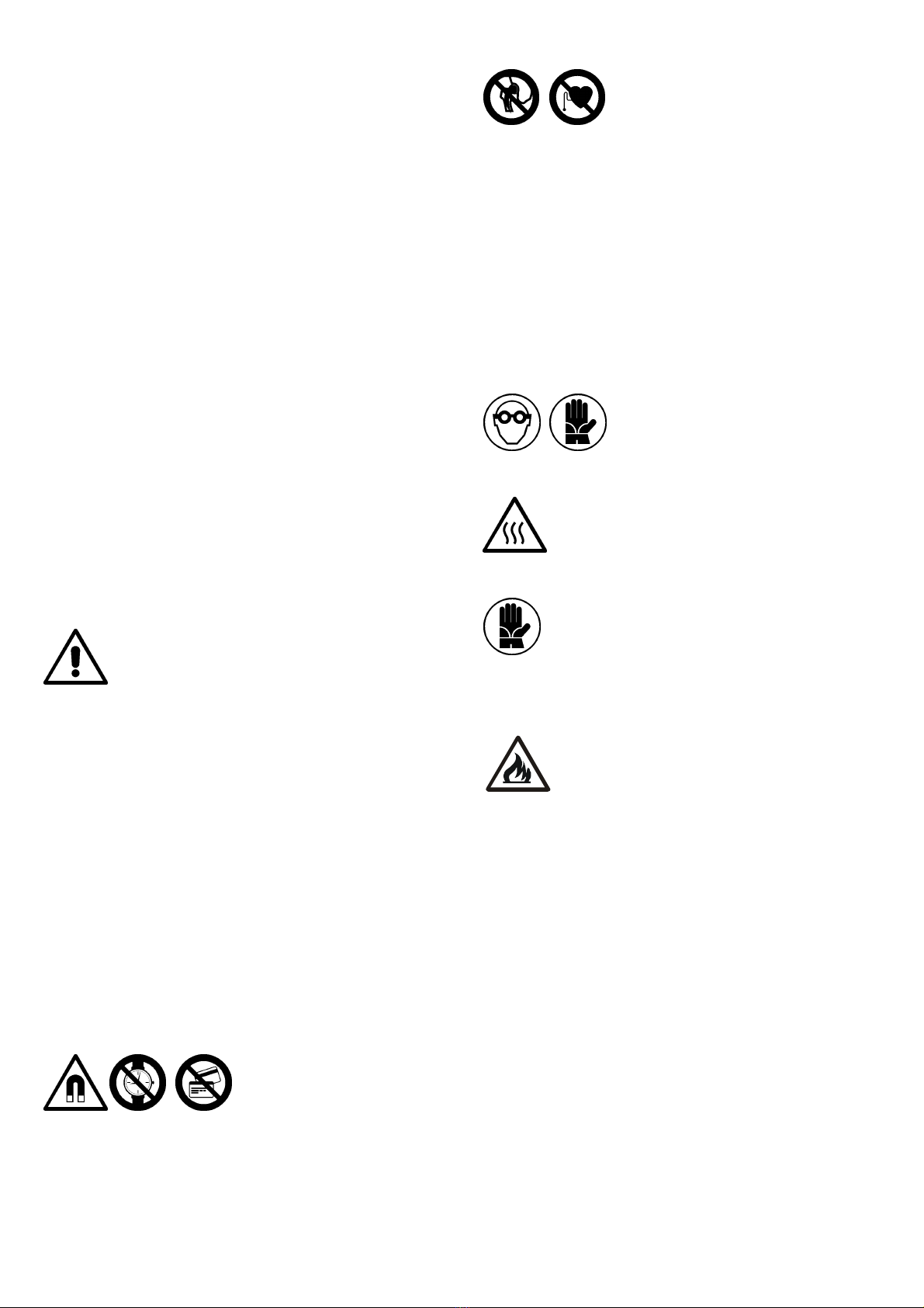
Ricordare che questo genere
di macchine genera forti
campi magnetici che possono
causare forte attrazione su
metalli magnetici, incluse le protesi metalliche, danneggiare
gli orologi, carte a banda magnetica e supporti magnetici per
dati.
I portatori di pace-maker, protesi
metalliche ed acustiche, ed ogni altro
tipo di dispositivo medico impiantabile,
prima di avvicinarsi al luogo di
saldatura, devono consultare il proprio medico.
Per limitare l’esposizione al campo magnetico:
- tenere i cavi di saldatura il più possibile vicini tra loro,
eventualmente arrotolandoli tra loro;
- tenere i cavi di saldatura il più lontano possibile dal corpo;
- tenere entrambi i cavi di saldatura dal lato della mano che
impugna l’attrezzo di saldatura, non posizionare mai il corpo
all’interno del percorso descritto dai cavi;
- collegare il cavo di massa il più vicino possibile all’area di
saldatura.
L’elevata corrente elettrica utilizzata dalla macchina per eseguire
la saldatura può surriscaldare ogni oggetto in metallo che
inavvertitamente sia soggetto al suo passaggio. Non indossare
anelli, orologi metallici, e vestiti con parti od accessori
metallici.
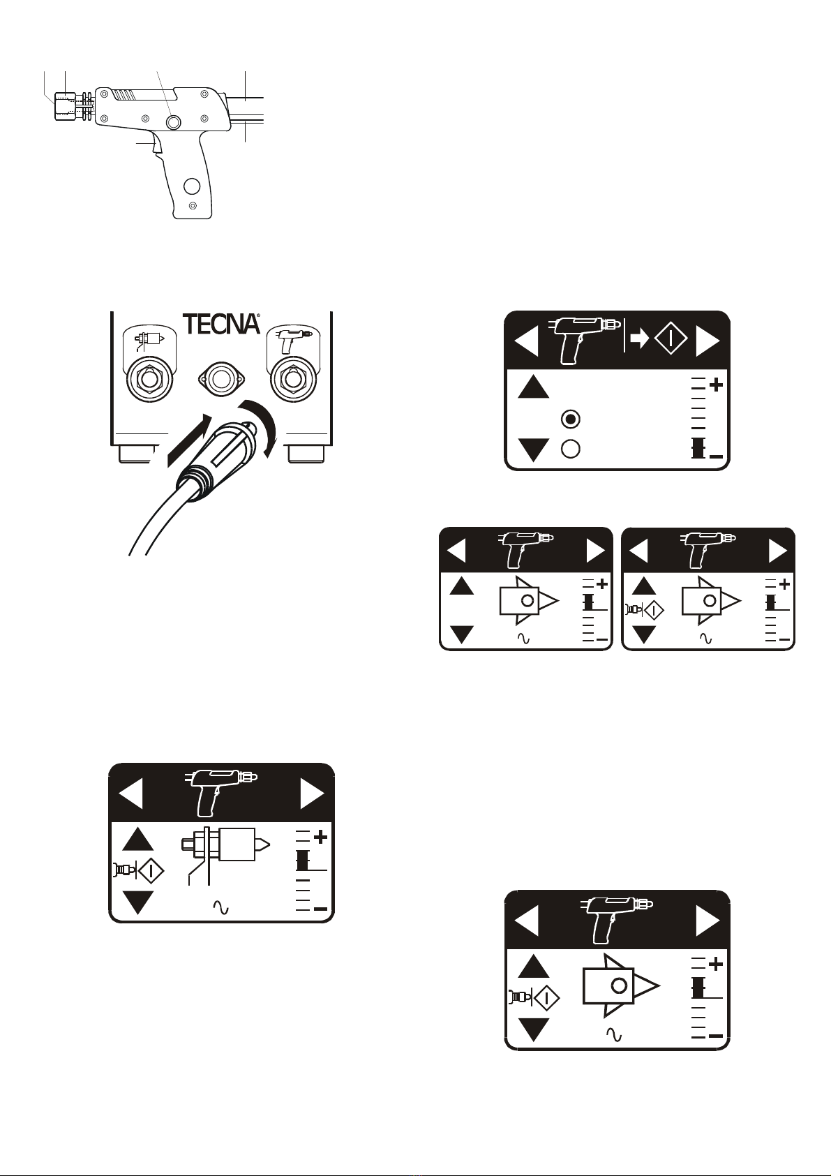
Durante la lavorazione possono
presentarsi schizzi di materiale
incandescente. Il personale deve
indossare adeguati dispositivi di
protezione: occhiali, guanti di sicurezza, e un adeguato
vestiario
Alcune parti della macchina (elettrodi e cavi)
possono scaldarsi eccessivamente se la macchina
viene utilizzata con ritmi di lavoro troppo elevati.
Analizzare le condizioni di lavoro ed utilizzare, se
necessario, adeguati dispositivi di protezione individuale (guanti,
grembiuli ed altro vestiario).
Le lamiere sulle quali si eseguono le lavorazioni
raggiungono temperature molto elevate localizzate
nella zona dove si esegue la saldatura o il
riscaldamento. Verificare che non vi siano materiali
infiammabili a contatto o in prossimità delle lamiere sulle
quali si deve lavorare, anche all’interno della scocca.
Potrebbero incendiarsi durante la lavorazione. Utilizzare
guanti adeguati per proteggersi dalle scottature.
Tenere la zona circostante la saldatrice libera da
materiali infiammabili in quanto la lavorazione può
comportare proiezioni di particelle di metallo fuso. In
caso di incendio non deve essere utilizzata acqua
ma adeguati estintori.
Non trasportare la saldatrice tenendola per i cavi. Non spostare
la saldatrice tirandola per i cavi. Non togliere la spina dalla presa
tirandola per il cavo. Tenere i cavi lontano da fonti di calore, oli e
bordi affilati. Se mentre si lavora si danneggia il cavo di
alimentazione estrarre immediatamente la spina di
alimentazione. Non utilizzare la macchina se il cavo di
alimentazione è danneggiato.
La manutenzione della macchina va effettuata seguendo
scrupolosamente le indicazioni di sicurezza contenute nel
capitolo “MANUTENZIONE”.
Se la saldatrice viene a contatto con acqua che raggiunga le parti
interne, si deve immediatamente spegnere la macchina ed
estrarre la spina di alimentazione. La stessa procedura deve
essere seguita qualora si presenti qualsiasi situazione di rischio
di scossa elettrica. La messa in funzione della saldatrice dopo
una situazione di emergenza deve essere effettuata unicamente
da personale qualificato che deve eseguire le verifiche
necessarie sulla macchina.
Oltre alle indicazioni riportate in questo paragrafo tenere sempre
presenti le normative vigenti a cui si è soggetti.

7
PROGRAMMAZIONE
Questo paragrafo contiene indicazioni di carattere generale sulla
programmazione del controllo di saldatura EasyOne Sx1.
Indicazioni specifiche per le regolazioni per i diversi attrezzi di
saldatura sono contenute nei relativi paragrafi.
All’accensione vengono visualizzati nome e modello del controllo,
la versione del programma e la frequenza di funzionamento
rilevata.
SW VER. 1.0
Il controllo prevede due diversi tipi di regolazione; quello manuale
e programmi “sinergici” ottimizzati per i lavori più comuni.
Con i tasti ße Ýsi seleziona il programma desiderato.
1.5 30%
2.0 45%
43 %
12
Tramite i tasti Üe Þsi passa dalla programmazione dei
parametri di saldatura alla regolazione della funzione di auto
start.
43 %
12
AUTOSTART
ON 0.3s
OFF
Il diagramma in figura 1 (pag. 48) mostra tutte le pagine di
programmazione.
MODO MANUALE
In questa modalità l’operatore regola direttamente i valori di
tempo e corrente necessari. Questa modalità viene utilizzata per
tutti quei lavori per i quali non è previsto un programma specifico.
43 %
12
Per modificare i valori visualizzati premere il tasto + o –; il
simbolo del parametro tempo lampeggia e si può programmare
con i tasti + e –.
Con i tasti ße Ýsi passa tra la regolazione del tempo e quella
della corrente, l’icona del parametro che si modifica lampeggia.
L’indicatore a barre posto a destra fornisce una visione
immediata della regolazione.
MODALITA’ CON REGOLAZIONE DI TEMPO E CORRENTE
(“SINERGICA”)
Nelle modalità seguenti l’operatore richiama programmi
preimpostati di saldatura dedicati a svolgere lavori definiti.
Tramite i tasti + e – è possibile effettuare una
regolazione fine dei parametri di saldatura. Un
indicatore a barre a zero centrale mostra la regolazione
fine effettuata. Il controllo determina automaticamente
le variazioni di tempo e corrente tramite curve
sinergiche.
Nella parte bassa del display vengono mostrati i valori di tempo e
corrente che saranno realmente utilizzati.
1.5 30% 6.0 80%
1.5 40% 1.5 40%

8
PISTOLA MULTIFUNZIONE
C
A D EB
F
A Ghiera di bloccaggio
mandrino.
B Mandrino
portautensile.
C Grilletto di comando
saldatura.
D Pulsante di
regolazione remota.
E Cavo corrente di
saldatura.
F Cavetto di comando.
Preparazione pistola multifunzione
Montare sulla pistola gli accessori necessari al lavoro da
eseguire. Serrare bene la ghiera (A) con chiave in dotazione.
Collegare alla presa (6) la pistola e alla presa (7) il cavo di
massa, le spine devono essere serrate con forza.
T-Spot 110
12
Collegare la spina segnali alla presa (8).
Collegamento cavo di massa
Saldare la connessione di massa sulla stessa lamiera sulla quale
si deve eseguire la saldatura. La corrente di saldatura non deve
scorrere su cerniere o altre parti perché potrebbe danneggiarle.
Il cavo di massa va saldato in posizione vicina alla zona di
saldatura. Variazioni di questa distanza possono richiedere una
diversa regolazione del controllo di saldatura: più è lontana la
massa dalla zona da puntare, maggiore dovranno essere la
corrente e il tempo di saldatura.
Un apposito programma di saldatura rende più agevole questo
compito.
2.0 45%
1) Montare sulla pistola l’elettrodo a testa piana per la ricalcatura
art. 7650.
2) Rimuovere la vernice dal punto in cui si deve collegare la
massa a saldare.
3) Poggiare la massa a saldare sulla lamiera esercitando una
leggera forza.
4) Premere con forza la pistola vicino alla massa e premere il
grilletto.
5) Avvitare il dado della massa a saldare fino a portarlo in
appoggio sulla lamiera.
Funzione di regolazione remota
Tramite il pulsante (D) è possibile la rapida selezione remota dei
programmi e la regolazione fine.
Premendo brevemente il pulsante si cambia il programma
selezionato (equivale a premere il tasto ß).
Tenendo premuto il pulsante si modifica la regolazione fine nei
programmi sinergici. Al primo azionamento le regolazioni
vengono aumentate, all’azionamento successivo vengono
diminuite.
Lo stesso pulsante può essere utilizzato per azzerare le
condizioni di errore.
Regolazione funzione “Autostart”
La funzione di autostart consente di avviare automaticamente la
saldatura quando la pistola multifunzione viene a contatto con la
lamiera. Tramite una apposita pagina di programmazione si può
attivare la funzione (con i tasti ße Ý) e regolare il ritardo tra il
contatto e l’avvio della saldatura (con i tasti + e –).
AUTOSTART
ON 0.3s
OFF
L’autostart si utilizza solo con la pistola multifunzione.
L’attivazione della funzione è indicata da un’apposita icona sul
display.
1.5 30%
1.5 30%
Autostart disattivato Autostart attivato
RADDRIZZATURA DI DEFORMAZIONI RILEVANTI SU
LAMIERATI DELLA CARROZZERIA.
Si possono seguire due diverse procedure:
1) Utilizzo della stella a tre punte e successiva deformazione con
l’estrattore a percussione.
2) Saldatura di fili ondulati o rondelle asolate e successiva
deformazione con apposite attrezzature.
La lamiera sulla quale si esegue la lavorazione deve essere
pulita, eventuali tracce di ossidazione o vernice vanno rimosse.
UTILIZZO DELLA STELLA A TRE PUNTE
Utilizzare l’apposito programma sinergico sotto raffigurato.
1.5 30%
Tenere la pistola perpendicolare alla lamiera, premendo con
forza moderata.

9
Avviare la saldatura premendo il grilletto (se è attiva la funzione
di auto start la saldatura parte automaticamente). Allentare la
forza sulla pistola solo dopo aver eseguito la saldatura.
Utilizzando il martello a scorrimento tirare la lamiera per riportarla
nella posizione desiderata.
Per staccare la stella a tre punte dalla lamiera ruotare la pistola.
SALDATURA DI FILI ONDULATI O RONDELLE ASOLATE
Per l’esecuzione di questi lavori sono previsti appositi programmi
sinergici.
1.5 40% 1.5 40%
Per la saldatura di fili ondulati utilizzare l’elettrodo art. 7657. Per
la saldatura di rondelle asolate utilizzare l’elettrodo art. 7693.
Tenere la pistola perpendicolare alla lamiera, premendo con
forza moderata, ed eseguire la saldatura.
La raddrizzatura si esegue con apposite attrezzature.
RICALCATURA
Al termine della raddrizzatura può essere necessario eliminare
eventuali sporgenze residue.
L’operazione può essere effettuata con la ricalcatura a caldo
utilizzando l’elettrodo a testa piana art. 7650. Per questa
lavorazione è previsto un apposito programma sotto raffigurato.
6.0 80%
Effettuare la ricalcatura tenendo la pistola perfettamente
perpendicolare alla lamiera e premendo con forza.
La stessa procedura può essere utilizzata per eseguire
l’appiattimento di piccole ammaccature della carrozzeria rivolte
verso l’esterno.
RISCALDAMENTI LOCALIZZATI CON ELETTRODO DI
CARBONE
La macchina può essere utilizzata per riscaldare lamiere di
spessore sottile per contrarre gli allungamenti. La lamiera da
trattare deve essere perfettamente pulita e lucidata.
Montare sulla pistola l’elettrodo in carbone art. 7656. Tramite
l’apposito programma si effettua la regolazione della corrente.
37%
Il riscaldamento si effettua facendo scorrere l’elettrodo sulla
lamiera esercitando una leggera pressione. Effettuare un
movimento circolare con velocità uniforme, senza fermarsi.
All’avvio della saldatura (tramite il grilletto o in modo automatico
con la funzione auto start) la corrente impostata viene erogata
per un tempo massimo di 4 secondi; se questo tempo non fosse
sufficiente ad eseguire il riscaldamento desiderato rilasciare il
grilletto ed azionarlo nuovamente.
Si termina l’operazione di riscaldamento rilasciando il grilletto o
staccando l’elettrodo dalla lamiera.
Dopo riscaldamento raffreddare immediatamente con un panno
umido.
SALDATURA DI RIVETTI
Un apposito programma sinergico è predisposto per la saldatura
di rivetti diametro 3 mm come quelli forniti in dotazione (art. 7666
e 7667). Montare sulla pistola l’elettrodo art. 7649.
5.0 65%
Effettuare la saldatura tenendo la pistola perfettamente
perpendicolare alla lamiera e premendo moderatamente.
FUNZIONE DI CONTROLLO SALDATURA INTERROTTA
Se il grilletto viene rilasciato prima del termine della saldatura
viene visualizzato un apposito errore per segnalare che la
saldatura non è stata completata.
L’errore si azzera premendo un tasto o premendo il pulsante di
regolazione remota sull’impugnatura.

10
MANUTENZIONE
Le seguenti operazioni di manutenzione vanno eseguite
esclusivamente da personale specializzato, in grado di
effettuare le operazioni indicate in condizioni di sicurezza.
Quando possibile la saldatrice deve essere sezionata
dall’alimentazione elettrica.
MANUTENZIONE ORDINARIA
GENERATORE
Mantenere puliti e ben serrati le prese (6-7) della corrente di
saldatura. Eliminare eventuali tracce di ossidazione con carta
abrasiva fine.
Verificare frequentemente lo stato del cavo di alimentazione e
della spina. Sostituire il cavo in presenza di screpolature, tagli,
forti abrasioni, ecc.
Verificare che la saldatrice sia collegata al conduttore di
protezione, che il filo di terra all’interno del cavo di
alimentazione non sia interrotto.
Controllare periodicamente l'efficienza della messa a terra
dell'impianto.
Mantenere la macchina pulita. Particelle di metallo sono
attratte dal campo magnetico creato dalla saldatrice durante il
funzionamento. Non pulire la saldatrice con getti d’acqua che
potrebbero penetrare al suo interno, evitare inoltre di utilizzare
forti solventi, diluenti o benzine che potrebbero danneggiare le
vernici o le parti in plastica della macchina.
PISTOLA MULTIFUNZIONE
Mantenere puliti e ben serrati le spine e le connessioni della
corrente di saldatura. Eliminare eventuali tracce di ossidazione
con carta abrasiva fine.
I cavi di saldatura devono essere isolati e in perfette condizioni
con attenzione ai punti dove subiscono flessioni.
MANUTENZIONE STRAORDINARIA
Eventuali interventi all’interno della saldatrice, devono
essere eseguiti solo da tecnici specializzati.
Il generatore e la pistola multifunzione, sono dotati di protezione
termostatica. In caso di surriscaldamento, all’avvio della
saldatura viene mostrato il seguente errore.
L’errore si azzera premendo un tasto o premendo il pulsante di
set sull’impugnatura della pistola multifunzione. L’errore si azzera
automaticamente quando la macchina si raffredda.
Se all’avvio della saldatura non si ottiene l’erogazione di corrente
verificare che il generatore riceva il comando di avvio saldatura.
La ricezione del comando viene indicata sul display con la
modifica del disegno dell’attrezzo, come da seguente figura.
1.5 30%
Se, eseguendo la saldatura, la macchina provoca un forte
assorbimento di corrente, tale da far aprire gli interruttori
automatici o intervenire i fusibili posti sulla linea di alimentazione,
ciò può essere dovuto al fatto che precedentemente la macchina
è stata spenta, o è mancata l’alimentazione, mentre eseguiva
una saldatura. In questo caso è necessario eseguire la seguente
procedura prima di riprendere il lavoro, per ripristinare la normale
condizione di magnetizzazione del trasformatore. Effettuare
alcune saldature con un isolante tra gli elettrodi con una
regolazione di corrente prima bassa poi progressivamente
crescente. Rimuovere l’isolante tra gli elettrodi ed eseguire
qualche saldatura con una bassa regolazione di corrente.
Eseguita questa procedura saranno ripristinate le normali
condizioni di funzionamento.
Se le prestazioni sono inferiori al previsto controllare:
Che durante la saldatura non vi sia una caduta di tensione
superiore al 15 %. Una caduta di tensione eccessiva può
essere provocata da una sezione insufficiente dei cavi
dell’impianto di alimentazione o dall’uso di prolunghe con
sezioni insufficienti.
Che i parametri di saldatura impostati nel controllo siano
corretti.

11
EN
INDEX
INTRODUCTION.............................................................................................................................. 12
SYMBOLS........................................................................................................................................ 12
IDENTIFICATION OF WELDER MAIN PARTS................................................................................ 13
STANDARD ACCESSORIES........................................................................................................... 13
TECHNICAL FEATURES................................................................................................................. 13
GENERAL DESCRIPTION .............................................................................................................. 14
INSTALLATION............................................................................................................................... 14
ELECTRIC INSTALLATION ............................................................................................................. 14
OPTIONAL TROLLEY INSTALLATION ........................................................................................... 14
START-UP ....................................................................................................................................... 15
SAFETY REQUIREMENTS .............................................................................................................15
PROGRAMMING ............................................................................................................................. 16
MULTIFUNCTION GUN................................................................................................................... 17
STRAIGHTENING OF LARGE DEFORMATIONS ON BODY PANELS .......................................... 17
UPSETTING..................................................................................................................................... 18
LOCALIZED HEATING WITH CARBON ELECTRODE ................................................................... 18
RIVETS WELDING........................................................................................................................... 18
INTERRUPTED WELD CHECK FUNCTION.................................................................................... 18
MAINTENANCE............................................................................................................................... 19
ORDINARY MAINTENANCE ........................................................................................................... 19
EXTRAORDINARY MAINTENANCE ............................................................................................... 19

12
INTRODUCTION
CAREFULLY READ THIS INSTRUCTION MANUAL
BEFORE INSTALLING AND OPERATING THE
WELDER
The purpose of this manual, and the attached documents, is to
transmit information required for the responsible and safe use of
this product. It includes information on product safety, installation,
operation, maintenance and disposal. This manual is addressed
to the plant manager who must make sure it is read by personnel
in charge of welder installation, operation and maintenance. One
must ensure that the information, provided in this document and
in the enclosed documents, has been read and fully understood
before operating the machine. This manual must be stored with
care in a well-known place that is easy to reach and should be
consulted whenever doubts of any kind arise.
Since this manual is an integral and essential part of the product,
it must be kept for the machine's entire operating life and
accompany the machine in all changes of ownership that occur
during its lifetime.
The time invested in adhering to these instructions will be amply
rewarded by the perfect working order and safety of the machine.
It is mandatory to comply with that which is outlined in this
manual.
The welders described in this manual were designed for being used
only for professional purposes in industrial environments and are
classified Class A resistance welders. They must not be used at
home or on public low voltage power lines which supply domestic
facilities, which could cause radiofrequency interference.
Use the machine only with original accessories or approved by
the manufacturer.
Any modifications are forbidden, even the slightest, because they
could compromise machine safety and consequently invalidate
the welder's CE certification.
This welder is to be used for the body repairs described in this
manual. The welder should not be used for other purposes and is
not suitable for production work.
TECNA S.p.A. is not responsible for any injury or damage to
people, animals, property and to the welder itself either caused
by:
- failure to comply with all requirements of current safety
standards;
- wrong installation;
- improper or incorrect use of the welder;
- non-compliant use as compared to that specified in this manual;
- lack of maintenance;
- changes or tampering, even slight, or any unauthorized
intervention;
- use of non-original or incompatible accessories or spare parts;
- total or partial failure to comply with instructions;
- special events.
The content of this manual is the property of TECNA S.p.A. and
is protected by copyright. All rights reserved. This manual may
not be reproduced, even partially, for uses other than to support
the product, subject-matter of this manual, without prior written
permission.
Only for Countries belonging to the EC:
In accordance to European Directive 2002/96/EC
for Waste Electrical and Electronic Equipment
(WEEE), the presence of this symbol indicates that
the product shall not be disposed of as urban
waste. Arrange for separate collection. Since the
user is responsible for properly disposing of the product, he/she
should contact the local authority or retailer. Illegal disposal of
this waste will be sanctioned.
Correct disposal will help maximize recovery, recycling and reuse
of materials while minimizing potential adverse effects on the
environment and health.
SYMBOLS
The following symbols are used in this manual and on the
machine to: highlight potential hazards, indicate prohibitions and
requirements for safe product use and to identify machine parts.
WARNING! The information contained in this
section is of utmost importance. Read it carefully.
WARNING! The machine generates magnetic
fields.
WARNING! Part subject to heat.
WARNING! Fire hazard.
Personnel must wear safety goggles.
Personnel must wear safety gloves.
Personnel must read this instruction manual.
No access to metallic implant carriers.
No access to pacemaker carriers.
Do not wear watches.
Do not wear magnetic stripe documents.
Welding time.
Welding current intensity.
Do not dispose of electrical equipment with
household waste.

13
IDENTIFICATION OF WELDER MAIN PARTS
T-Sp ot 110
5
8
6
7
N°
YEAR
kg
A
NNO
S/N
W
EIGHT
PESO
ITEM
A
RT.
S
50
Hz
1N
U
U
202cc
kVA
A
V
f
V
I
MADEIN ITALY
40024 Caste l S. Pietro T. - Italy
WWW.TECNA.NET - C.P. 117
T-S pot 110
m
S
p
kVA
A
1
3
4
1 - Power switch.
3 - Power supply cable.
4 - Rating plate and serial number.
5 - EasyOne Sx1 control unit.
6 - Socket for multifunction gun.
7 - Socket for multifunction gun ground cable.
8 - Signals socket for multifunction gun.
STANDARD ACCESSORIES
The machine is delivered complete with the following parts.
1 Item 8068 – Multifunction gun with 50 mm2cable L= 2 m
1 Item 8069 – Ground cable for multifunction gun 50 mm2
L= 2 m
1 Item 7638 – Percussion puller with reduced dimension sliding
hammer
1 Instruction Manual
1 Item 7634 – Kit with accessories and consumables for
multifunction gun
Optional items:
Item 3461T – Trolley
Item 3461N – Trolley
TECHNICAL FEATURES
Power supply * U1N
f
V
Hz
230
50
Conventional power at 50% S50 kVA 2.5
Permanent power at 100% SpkVA 1.8
Max. input current in short
circuit I1cc A 86
Max. short circuit current I2cc kA 2.25
Thermal current at 100% I2p A 200
Secondary no load voltage U20 V8.8
Cooling Air
Insulation class F
IP rating IP21
Dimensions
H
W
D
mm
mm
mm
320
200
360
Generator net weight kg 18
CONNECTION DATA
Power cable
Length
Core section
m
mm2
3.5
2.5
Required distribution system
cables / extension cords
Total L <= 15 m
Total L = 30 m
mm2
mm2
2.5
4
Required line protection
Plug
Fuses (gG)
Delayed fuses (aM)
Circuit breaker (C curve)
Circuit breaker (D curve)
A
A
A
A
A
16
-
16
16
16
Environmental operating conditions
Temperature
Humidity (without condensate)
°C
%/°C
%/°C
5-40
50/40
90/20
EMISSION DATA
Airborne noise dB(A) < 70
Vibrations level m/s2< 2.5
Measurement conditions:
welding time
welding current
work rate
cicli
kA
welds/min
5
2
5
* Other voltages and frequencies available on request

14
GENERAL DESCRIPTION
The T-Spot 110 machine is designed to repair steel car bodies,
with special regards to sheet metal straightening, rivets welding
and localized heating with carbon electrode.
The button on the multifunction gun is used for quickly and
remotely selecting programmes and making fine adjustments.
The EasyOne Sx1 built-in microprocessor control unit allows
quick and easy machine adjustment through the graphic LCD.
In addition to the manual control mode, there are a number of
optimized welding programmes for carrying out the most common
jobs, featuring fine adjustments with synergic curve.
The adjustment of the half-period time permits more precise work
and minimum time execution equivalent to half that of
conventional machines.
The "AUTOSTART" feature facilitates the use of the multifunction
gun by starting the weld automatically when the tool is in contact
with the sheet.
The microprocessor indicates if the weld is carried out faster than
programmed, due to the early release of the control trigger, which
avoids carrying out wrong welds inadvertently.
The transformer and the multifunction gun are equipped with
thermal protection.
INSTALLATION
First of all check that the place in which the welder is used
complies with the specifications outlined in the "SAFETY
REQUIREMENTS" paragraph.
On receiving the welder, check that the outside of the packing is
intact, otherwise report any anomalies to the person in charge.
Any damage to the packing should give rise to doubts as far as
what condition its contents might be in.
Only use a forklift to handle the packing, paying attention both to
its weight and other handling instructions specified on the
packing.
Place the package in a horizontal position and open the upper
part of the package; take out the supplied accessories.
Remove the machine from the packing. Since this machine is
heavy, two persons should always be present to lift and handle it,
using the side handles.
Visually check that the machine is intact. Check that all the
machine's standard accessories are present; promptly notify the
manufacturer of any missing parts. All the materials that make up
the package must be disposed of in compliance with the current
laws on environmental protection.
ELECTRIC INSTALLATION
The installation should be carried out by
qualified personnel, aware of safety rules, who
closely adhere to the directions contained in this
manual.
The welders described in this manual were designed for being
used only for professional purposes in industrial environments
and are classified as class A resistance welders. WARNING:
class A resistance welders are not to be used on public low
voltage lines which supply domestic facilities as this could cause
radiofrequency interference.
Since the welder can be supplied at different supply voltages,
check that mains voltage matches that indicated on the rating
plate before connecting the machine to the line. This welder is
built to be used only at the supply voltage specified on the rating
plate and is not set-up to be adjusted for other voltages.
Connect a plug to the power supply cable; the plug capacity is
indicated in the technical features table (page 13).
The supply cable wires are coloured brown and light blue whilst
the ground cable is yellow/green. Figure 2 (page 49) shows some
connection examples.
It is compulsory to connect the welder to the protection lead
(ground cable). Check that the system's protection lead is
efficient and complies with regulations in force.
The technical features table (page 13) outlines supply line
requirements.
Do not use extension leads but if strictly necessary they should
be as short as possible and have a core section appropriate to
their length (indicated in the technical features table on page 13).
OPTIONAL TROLLEY INSTALLATION
The machine can be supplied with an optional trolley.
If trolley is supplied disassembled, refer to the assembly
instructions contained inside the trolley packing. Mount the
machine on the trolley only after it has been fully assembled and
all screws have been duly tightened.
Secure the machine to the trolley by means of the specific screw.

15
START-UP
Place the machine on a horizontal surface, either a table, a trolley
or even just on the floor, and check its stability. Ensure that it
cannot fall or tip over even if pulled by cables.
If using the optional trolley, check that the floor is flat, smooth and
devoid of obstacles. When handling the trolley, the presence of
obstacles on the floor could lock the wheels and overturn the
machine.
Check that the machine is not exposed to water splashes or
penetration of liquids, dirt, metal filings, etc.
Check that the cables do not get in people's way and do not
cause danger or risk of being damaged.
Check the machine's condition each time before using it and also
that of the power cable and plug; do not use the machine if you
notice any defects.
Before connecting the plug and turning on the machine,
check that all safety requirements have been met.
Connect the plug to a socket the specs of which should match
supplied specifications (rating and sizing of the safety devices
outlined in the technical features table).
Connect the tools you intend using to the generator. Connection
directions, adjustments and operating modes are specified in the
relevant paragraphs.
Strictly respect all safety requirements when working.
Once done, unplug the plug and store the welder in a dry,
sheltered place.
SAFETY REQUIREMENTS
This paragraph contains important information
on how to use the product safely. Anyone using
this product must read and understand its
contents before using the machine. You must
follow what is indicated.
Use the welder in a place that meets the following characteristics:
Indoors (it should never be used outdoors).
At room temperature from 5 to 40 °C and at an altitude that
does not exceed 1000 metres. The welder may even be
stored at -20 °C for storage purposes only.
In a well-ventilated, dry area, free from dust, vapours, acid
fumes.
The workplace must be free of flammable materials as the job
may involve projections of molten metal particles. You may
not use the machine in explosive or fire hazard environments.
In a well-lit room in relation to the work to be done.
If using the optional trolley, the floor must be flat, smooth and
devoid of obstacles.
If you foresee using the machine for welds that might generate
fumes, install an adequate extraction system.
Keep in mind that this type of
machine generates strong
magnetic fields that might
cause strong attraction to
magnetic metals, including metal implants, or damage
watches, magnetic stripe cards and magnetic data mediums.
Pacemaker, metallic implant and
hearing aid carriers, or anyone who
carries any other type of implantable
medical device, should consult their
doctor before approaching the welding area.
Proceed as follows to limit exposure to magnetic fields:
- keep the welding cables as close as possible to each other,
eventually rolling them up together;
- keep the welding cables as far as possible from your body;
- keep both welding cables on the side of the hand that holds the
welding tool and never place your body on the inside of the
cable route;
- connect the ground cable as close as possible to the welding
area.
The high power used by the machine to carry out the weld may
overheat any metal object it might cross inadvertently. Do not
wear rings, metal watches and clothes that have metal parts
or accessories.
Splashing of very hot material may occur
during the processing. Personnel should
wear suitable personal protective
equipment: goggles, safety work gloves
and proper clothes.
Certain parts of the machine (electrodes and cables)
might overheat excessively if the machine works at
welding rates that are too high. Analyze working
conditions and use suitable personal protective
equipment (gloves, overalls and other clothing), if necessary.
The sheets on which work is performed reach very
high temperatures in the area in which the welding or
heating takes place. Check that there are no
flammable materials in contact with or near the
sheets on which to work, even within the body, as they
could catch fire during the process. Use suitable gloves that
protect hands from scalding.
Keep the area around the welder clear of flammable
materials as the job may involve projections of
molten metal particles. In case of fire do not use
water but suitable fire extinguishers.
Do not carry or hold the machine by the cables. Do not move the
welder by pulling on the cables. Do not unplug the plug by pulling
the cable. Keep the cables away from heat, oil and sharp edges.
If you damage the power cable while working, remove the power
plug at once. Do not use the machine if the power cable is
damaged in any way.
When performing machine maintenance, strictly adhere to the
safety warnings in the "MAINTENANCE" chapter.
If the welder comes into contact with water that seeps inside, turn
off the machine immediately and remove the power plug. Also
follow this same procedure in any situation where there is risk of
electric shock. Only qualified personnel who know how to carry
out the necessary machine checks may start the welder after an
emergency situation.
In addition to the information provided in this paragraph, always
keep in mind the relevant prevailing regulations.

16
PROGRAMMING
This paragraph contains general guidelines on how to
programme the EasyOne Sx1 weld control unit. Specific
instructions on the adjustments of different welding tools are
contained in the relative paragraphs.
Control unit name, model, programme version and operating
frequency are displayed when turned on.
SW VER. 1.0
The control unit has two types of adjustments: the manual one
and the "synergic" programmes optimized for executing the most
common jobs.
Use buttons ßand Ýto select the required programme.
1.5 30%
2.0 45%
43 %
12
Use buttons Üand Þto switch from the weld parameters
programming to the setting of the auto start function.
43 %
12
AUTOSTART
ON 0.3s
OFF
The diagram in figure 1 (page 48) shows all the programming
pages.
MANUAL MODE
In this mode the operator adjusts the required time and current
values. This mode is used for all those jobs for which a specific
programme has not been envisaged.
43 %
12
In order to change the displayed values, press button + or –; the
time parameter symbol flashes; use buttons + and – to
programme.
Use buttons ßand Ýto switch from time adjustment to current
adjustment and vice versa. The icon of the parameter you
changed will flash.
The bar indicator on the right-hand side gives an instant view of
the adjustment.
TIME AND CURRENT SETTING MODE ("SYNERGIC")
The operator recalls preset weld programmes, dedicated to
carrying out the set jobs, as follows:
Use buttons + and – to finely adjust the weld
parameters. A central zero bar indicator shows the fine
adjustment. The control unit automatically determines
the time and current changes through synergic curves.
The time and current values that will actually be used
are displayed at the bottom.
1.5 30% 6.0 80%
1.5 40% 1.5 40%

17
MULTIFUNCTION GUN
C
A D EB
F
A Spindle-locking ring
nut.
B Tool-holding spindle.
C Weld control trigger.
D Remote adjustment
button.
E Weld current cable.
F Control cable.
Preparing the multifunction gun
Mount on the gun the accessories, required for the job to be
carried out. Tighten the ring nut (A) using the supplied wrench.
Connect the gun to the socket (6) and the ground cable to the
socket (7). The plugs should be tightened strongly.
T-Spot 110
12
Connect the signals plug to the socket (8).
Ground cable connection
Weld the ground connection to the sheet on which the weld is to
be carried out. Weld current should not touch hinges or other
parts as it might ruin them.
Weld the ground cable near the welding area. When this distance
changes, a different adjustment of the weld control unit might be
needed: the farther the ground from the area to be spot-welded,
the greater the welding current and time.
A special welding programme makes this task easier.
2.0 45%
1) Mount the flat head electrode on the gun for the upsetting,
item 7650.
2) Remove paint from the point in which the universal fast
ground is to be connected.
3) Place the universal fast ground on the sheet, applying some
force.
4) Press down the gun firmly, near the ground, and then press
the trigger.
5) Tighten the nut of the universal fast ground until it bears on
the sheet.
Remote adjustment
Use this button (D) for the quick and remote selection of
programmes and fine adjustments.
Press the button briefly to change the selected programme (the
same as pressing button ß).
Hold down the button to change the fine adjustment in the
synergic programmes. The first time the button is held down the
adjustments increase, the second time they decrease and so on.
This button can also be used to reset error conditions.
"Autostart" adjustment
Use the autostart function to start the weld automatically when
the multifunction gun comes into contact with the sheet. You can
activate this function, through a specific programming page (with
buttons ßand Ý), and adjust the delay between the contact and
the beginning of the weld (with buttons + and –).
AUTOSTART
ON 0.3s
OFF
The autostart function is used only with the multifunction gun.
The activation of the function is indicated by a specific icon on the
display.
1.5 30%
1.5 30%
Autostart OFF Autostart ON
STRAIGHTENING OF LARGE DEFORMATIONS ON BODY
PANELS
Two different procedures can be followed:
1) Using the 3-tip star and subsequent deforming using the
percussion puller.
2) Welding wavy wires or buttonholed washers and subsequent
deformation by means of specific tools.
The sheet on which you are working should be clean; any traces
of oxidation or paint should be removed.
USING THE 3-TIP STAR
Use the specific synergic programme shown below.
1.5 30%
Hold the gun perpendicular to the sheet, pressing moderately.

18
Start the welding procedure by pressing the trigger (if the
autostart function is on, the welding starts automatically).
Release the force on the gun only after having performed the
welding.
Use the slide hammer to pull the sheet back to the required
position.
Turn the gun to detach the 3-tip star from the sheet.
WELDING WAVY WIRES OR BUTTONHOLED WASHERS
Specific synergic programmes are envisaged to carry out these
jobs.
1.5 40% 1.5 40%
Use electrode item 7657 to weld wavy wires. Use electrode item
7693 to weld buttonholed washers.
Hold the gun perpendicular to the sheet, pressing moderately,
and weld it.
Straightening is carried out by means of specific tools.
UPSETTING
At the end of the straightening procedure, it might be necessary
to remove residual projections.
This operation can be carried out through the upsetting by using
the flat head electrode, item 7650. The specific programme
shown below has been envisaged for this process.
6.0 80%
Perform the upsetting by holding the gun perfectly perpendicular
to the sheet, pressing with force.
The same procedure can be used to flatten small dents in the
body, facing outwards.
LOCALIZED HEATING WITH CARBON ELECTRODE
The machine can be used to heat thin steel sheets to tauten
elongation. The sheet to be processed should be perfectly clean
and polished.
Mount carbon electrode item 7656 on the gun. Adjust current
through the specific programme.
37%
Heat the sheet by sliding the electrode on it and exerting slight
pressure. Carry out a circular movement at uniform speed,
without stopping.
When the welding begins (either by means of the trigger or
automatically through the autostart function), the set current is
supplied for 4 seconds at the most; if this time is not enough to
heat as required, release the trigger and pull it again.
The heating operation ends either by releasing the trigger or
detaching the electrode from the sheet.
After the heating operation, cool at once using a moist cloth.
RIVETS WELDING
A specific synergic programme has been prepared for welding Ø
3-mm rivets like those supplied (item 7666 and 7667). Mount
electrode item 7649 on the gun.
5.0 65%
Carry out the weld by holding the gun perfectly perpendicular to
the sheet, pressing moderately.
INTERRUPTED WELD CHECK FUNCTION
If the trigger is released before the end of the welding operation,
a specific error is displayed to signal that the weld was not
completed.
The error resets by pressing a key or by pressing the remote
adjustment button on the handle.

19
MAINTENANCE
The following maintenance operations must be carried out
by specialised personnel only, trained to accomplish them
under safety conditions. When possible, the welder must be
disconnected from electrical supply.
ORDINARY MAINTENANCE
GENERATOR
Keep the weld current connectors (6-7) clean and clamped.
Remove possible oxidation with fine sandpaper.
Periodically check the status of the power supply cable and
plug. Replace the cable in the presence of cracks, cuts, severe
abrasion, etc.
Check that the welder is connected to the safety conductor and
that the ground wire inside the power cable is not interrupted.
Periodically check the ground efficiency of the system.
Keep the welder clean. Metal scraps are attracted by the
magnetic field generated by the welder during the operation.
Do not wash the welding unit with jets of water which could
enter it nor use strong solvents, thinner or benzine that could
damage paint or machine plastic components.
Check that the fan works efficiently.
MULTIFUNCTION GUN
Keep the weld current plugs and connections clean and
clamped. Remove possible oxidation with fine sandpaper.
The weld cables must be insulated and in perfect working
order. Pay special attention to the points where they bend.
EXTRAORDINARY MAINTENANCE
Only skilled technicians are allowed to make the required
interventions inside the welder.
The generator and the multifunction gun are equipped with
thermal overload protection. The following error is displayed on
starting the weld if overheating occurs.
The error resets by pressing a key or the set button on the handle
of the multifunction gun. The error resets automatically when the
machine cools.
If current is not supplied on starting the weld, check that the
generator receives the command to start welding. The reception
of the command is shown on the display with the change of the
drawing of the tool, as shown in the figure below.
1.5 30%
If during welding the machine causes strong current
consumption, such as to open the circuit breakers or trip the
fuses located on the power line, this might be due to the fact that
the machine had been turned off previously or a power failure
occurred while it was carrying out a weld. In this case perform the
following procedure before resuming work in order to restore the
normal transformer magnetisation condition. Carry out some
welds with an insulator placed between the electrodes with
different current adjustments, first low ones, then progressively
higher. Remove the insulator between electrodes and execute
some welds with a low current adjustment. Routine operating
conditions are restored at the end of the foregoing procedure.
If performance is lower than expected, check:
that, when welding, voltage does not drop more than 15 %.
Excessive voltage drop can be caused by a poor core section
of the power supply system cables or the use of extension
leads with insufficient core sections.
that the weld parameters set in the control unit are correct.

20
FR
SOMMAIRE
INTRODUCTION.............................................................................................................................. 21
SYMBOLES UTILISES..................................................................................................................... 21
IDENTIFICATION DES PRINCIPAUX ELEMENTS DE LA SOUDEUSE ......................................... 22
EQUIPEMENT DE SERIE................................................................................................................ 22
CARACTERISTIQUES TECHNIQUES ............................................................................................ 22
DESCRIPTION GENERALE............................................................................................................23
INSTALLATION............................................................................................................................... 23
INSTALLATION ELECTRIQUE........................................................................................................ 23
INSTALLATION D'UN CHARIOT OPTIONNEL................................................................................ 23
MISE EN SERVICE.......................................................................................................................... 24
NORMES DE SECURITE ................................................................................................................ 24
PROGRAMMATION ........................................................................................................................ 25
PISTOLET MULTIFONCTION ......................................................................................................... 26
DRESSAGE DE DEFORMATIONS IMPORTANTES SUR DES TOLES DE LA CARROSSERIE. .. 26
REFOULAGE ................................................................................................................................... 27
CHAUFFAGES LOCALISES AVEC ELECTRODE DE CHARBON.................................................. 27
SOUDAGE DE RIVETS ................................................................................................................... 27
FONCTION DE CONTROLE DE SOUDAGE INTERROMPUE........................................................ 27
ENTRETIEN..................................................................................................................................... 28
ENTRETIEN ORDINAIRE ................................................................................................................ 28
ENTRETIEN EXTRAORDINAIRE .................................................................................................... 28
This manual suits for next models
1
Table of contents
Languages:
Other TECNA Welding System manuals