MCi CX420 User manual

CX420 (MS-1453) Disassemble Guide
■ 1、BATTERY PACK
■ 2、BOTTOM DOOR ASSY
■3、HDD MODULE
■4、ODD MODULE
■5、THERMAL-KIT、CPU、DRAM
■ 6、KEYBOARD
■ 7、SEPARATE UPPER CASE AND LOWER CASE
■ 8、LOWER CASE ASSY
■9、UPPER CASE ASSY
■10、LCD MODULE ASSY

CX420(MS-1453)Disassemble Guide
1、BATTERY PACK
1.1:Move the “Unlock’ button base on left picture
shows;
1.2:Release the “Release” button and move the
battery pack base on left picture.
Component P/N Qty
Battery Pack S9N-0362240-SB3 1

CX420(MS-1453)Disassemble Guide
2、BOTTOM DOOR ASSY
2.1:Remove the 3 screws (M2.5*5mm), then
remove the Bottom door.
Attention: the screw driver torque is: 2.0-2.5Kgf-cm
Component P/N Qty
Bottom door 307-452J213-F62 1
Screw E43-1255001-G68 3

CX420(MS-1453)Disassemble Guide
3、HDD MODULE
3.1:Remove the 2 screws(M2*3mm); then remove
the HDD DOOR.
Attention: the screw driver torque: 1.2-1.5Kgf-cm
Component P/N Qty
HDD DOOR 307-452K214-F62 1
Screw E43-1203013-G68 2
3.2:Remove the HDD Module according to the
direction as pic shows.

CX420(MS-1453)Disassemble Guide
3、HDD MODULE
3.3:Remove the 4 screws (M3*4mm) that stabilize
the bracket.
Attention: the screw driver torque is 3.0-3.5Kgf-cm
Component P/N Qty
Screw E43-1304009-G68 4
3.4:Remove the HDD bracket.
Component P/N Qty
HDD Bracket 307-4520111-H76 1
HDD Module S71-2450504-T14 1

CX420(MS-1453)Disassemble Guide
4、ODD MODULE
4.1:Remove the ODD Module according to the
direction as pic shows.
4.2:Remove ODD Bezel as below.
Component P/N Qty
ODD Bezel 307-452F213-F62 1
4.3:Remove 2pcs (M2*3mm) Screws, Then remove
ODD Bracket as below.
Attention: the screw driver torque is 1.5-2.0Kgf-cm
Component P/N Qty
Screw E43-1203013-G68 2
ODD Bracket E2M-6510211-Y28 1
ODD Module S7D-2270013-SI4 1

CX420(MS-1453)Disassemble Guide
5、THERMAL-KIT、CPU、DRAM
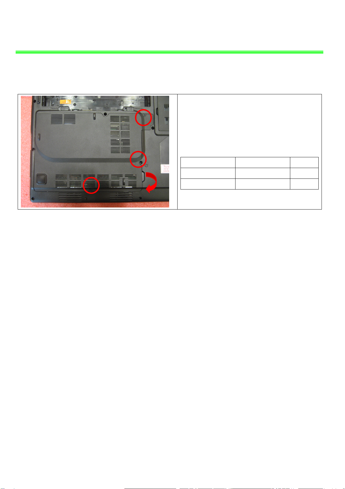
5.1:Remove the 4 screws(M2.5*5mm) and FAN
cable, after that remove the Fansink.
Attention:the screw driver torque is 2.0-2.5Kgf-cm
Component P/N Qty
Screw E43-1255001-G68 4
Fansink E32-0800482-S69 1
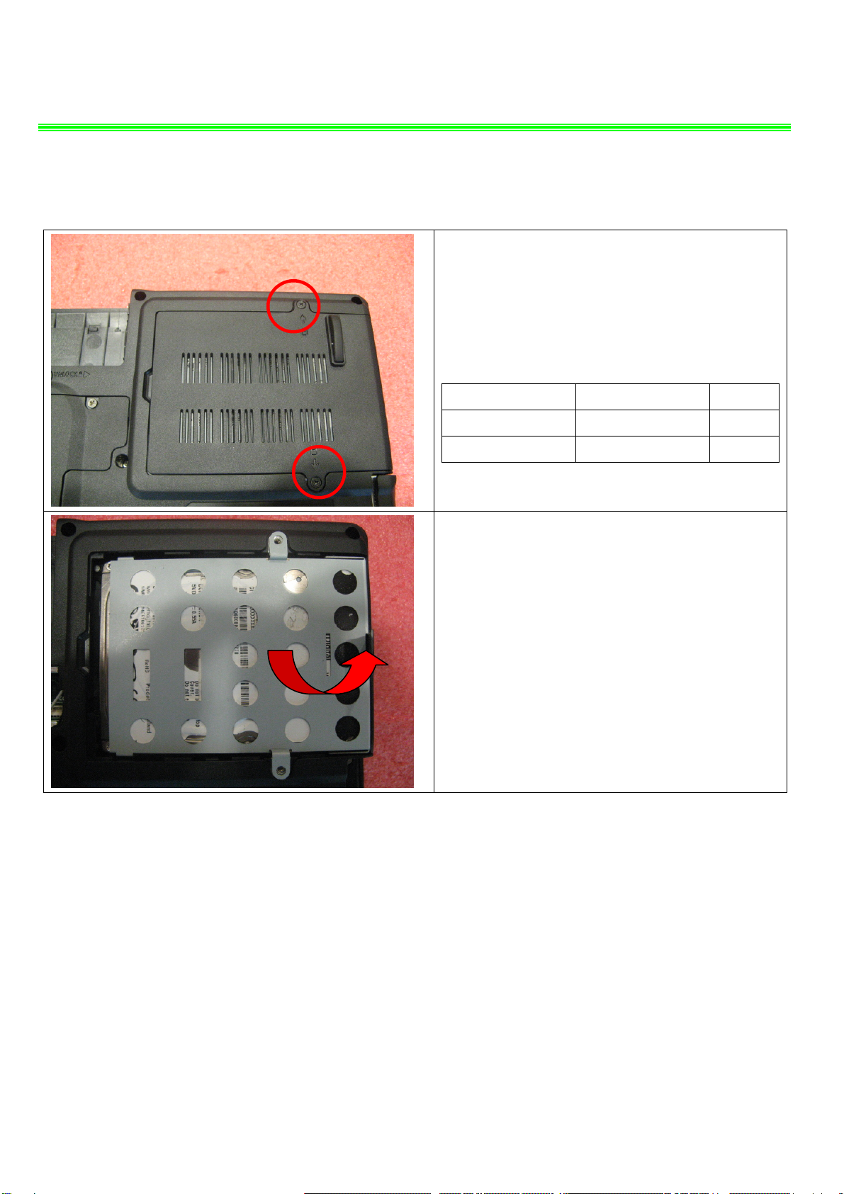
5.2:Open the CPU Slot with Screw Driver, then
remove CPU Module as below.
Component P/N Qty
CPU A13-2120106-I06 1
5.3:Push the two side shielding of RAM as pic
Shows; Then remove the RAM module according
the direction as pic shows.
Component P/N Qty
RAM Module S7C-S458804-S02 1
4
1
2
3

CX420(MS-1453)Disassemble Guide
6、KEYBOARD
6.1:Before remove K/B, firstly remove the
Middle Cover. Notice the rib on the cover.
Component P/N Qty
Hinge Cover 307-454E212-SE0 1
6.2:Remove the Keyboard.
6.3 :Firstly push connector according to the
direction as pic shows; then remove the cable.
Component P/N Qty
Keyboard S1N-2UUS211-SA0 1

CX420(MS-1453)Disassemble Guide
7、SEPARATE UPPER CASE AND LOWER CASE
7.1:Remove the 1 screw (M2.5*5mm) that stabilize
the hinge Cap, then remove Hinge cap.
Attention: the screw driver torque is 2.0-2.5Kgf-cm
Component P/N Qty
Screw E43-1255001-G68 1
7.2 :Remove the 4 screws (M2.5*7mm) that
stabilize the LCD hinge.
Attention: the screw driver torque is 3.2-3.5Kgf-cm
Component P/N Qty
Screw E43-1257002-G68 4

CX420(MS-1453)Disassemble Guide
7、SEPARATE UPPER CASE AND LOWER CASE
7.3:Remove the LVDS cable as pic shows:
7.4:Remove the CMOS Camera cable.
7.5:Remove the Bluetooth, MIC, Speaker cable.
Camera
MIC
Speaker
BT

CX420(MS-1453)Disassemble Guide
7、SEPARATE UPPER CASE AND LOWER CASE
7.6:Remove 4 screws(M2.5*5mm)
Attention: the screw driver torque is 2.0-2.5Kgf-cm
Component P/N Qty
Screw E43-1255001-G68 4
7.7:Remove 6 screws(M2.5*5mm)
Attention: the screw driver torque is 2.0-2.5Kgf-cm
Component P/N Qty
Screw E43-1255001-G68 6
7.8:Remove the 3 screws (M2*3mm)
Attention: the screw driver torque is 1.5-2.0Kgf-cm
Component P/N Qty
Screw E43-1203013-G68 3

CX420(MS-1453)Disassemble Guide
8、LOWER CASE ASSY
8.1:Remove the 2 screws (M2.5*5mm)
Attention: the screw driver torque is 2.0-2.5Kgf-cm
Component P/N Qty
Screw E43-1255001-G68 2
8.2:Remove the main board from Lower case.
Component P/N Qty
Main Board 607-14531-03S 1
8.3:Remove the 4 screws (M2*3mm), then remove
the Speaker module from lower case.
Attention: the screw driver torque is 1.5-2.0Kgf-cm
Component P/N Qty
Screw E43-1203013-G68 4
Speaker Module S33-A020221-F33 1
Lower Case 307-452D225-F62 1

CX420(MS-1453)Disassemble Guide
9、UPPER CASE ASSY
9.1:Remove the 2 magnet as left pic shows:
Component P/N Qty
Magnet E2M-4521011-SF7 2
9.2:Release the connector that stabilize the T/P
cable, then remove the T/P module FFC according
to direction of left pic shows;
Component P/N Qty
FFC Cable (To MB) K1C-1012042-J36 1
9.3:Remove the T/P module,
Component P/N Qty
Touchpad Module S78-3700360-SD2 1
Upper Case 307-454C412-SE0 1

CX420(MS-1453)Disassemble Guide
10、LCD MODULE ASSY
10.1:Remove the 8 cover rubber.
Component P/N Qty
Rubber E2Y-6740611-Y40 8
10.2:Remove the 4screws (M2.5*5mm). When
removing the LCD bezel, should begin from the
two sides, then the upside to downside.
Attention: the screw driver torque is 2.0-2.5Kgf-cm
Component P/N Qty
Screw E43-1255001-G68 4
LCD Bezel 307-453B211-U22 1

CX420(MS-1453)Disassemble Guide
10、LCD MODULE ASSY
10.3:Remove the 3 screws (M2.5*5mm); Remove
the Left LCD hinge.
Attention: the screw driver torque is 2.8-3.2Kgf-cm
Component P/N Qty
Screw E43-1255001-G68 3
Hinge L E2M-4520311-G60 1
10.4:Remove the 3 screws (M2.5*5mm); Remove
the Right LCD hinge.
Attention: the screw driver torque is 2.8-3.2Kgf-cm
Component P/N Qty
Screw E43-1255001-G68 3
Hinge R E2M-4520211-G60 1

CX420(MS-1453)Disassemble Guide
10、LCD MODULE ASSY
10.5:Remove the 6 screws (M2.5*5mm)
Attention: the screw driver torque is 2.0-2.5Kgf-cm
Component P/N Qty
Screw E43-1255001-G68 6
10.6:Remove the display module from LCD cover.
10.7:Remove the LVDS cable from display module.
Component P/N Qty
LVDS Cable K19-3017001-H39 1

CX420(MS-1453)Disassemble Guide
10、LCD MODULE ASSY
10.8:Remove the 6 screws (M2*3mm)
Attention: the screw driver torque is 1.5-2.0Kgf-cm
Component P/N Qty
Display Module S1J-442G002-A90 1
LCD BRACKET-L E2M-4520511-H76 1
LCD BRACKET-R E2M-4520411-H76 1
Screw E43-1203013-G68 6
10.9:Remove the 3 magnet on LCD cover;
Component P/N Qty
LCD Cover Magnet E2M-4521111-SF7 2
LCD Cover Magnet E2M-4521211-SF7 1
10.10:Remove the coaxial cable; then remove the
CMOS camera module according to the sequence
as pic shows.
Component P/N Qty
Coaxial Cable K10-3006074-H39 1
Camera Module S1F-0001580-B36 1

CX420(MS-1453)Disassemble Guide
10、LCD MODULE ASSY
10.11:Remove the MIC Module as left picture
show.
Component P/N Qty
MIC Module S34-2100920-K03 1
10.12:Remove the WIRELESS board from LCD
Cover.
Component P/N Qty
Wireless board 605-3870-010 1
Wireless cable K10-3010051-V03 1
LCD Cover 307-452A515-P89 1

CX420(MS-1453)Screws specification
Photo Screw specification Label
(M2.5*L5MM) black
(M2.5*L7MM) black
(M2*L3MM) black

CX420(MS-1453)screws specification
■ 1、BOTTOM DOOR ASSY total 15pcs screws
specification:
Photo Screw specification label
(M2*L3MM) black
(M2.5*L5mm) black
Table of contents
Popular Laptop manuals by other brands

Lenovo
Lenovo ThinkPad Z61E Guida all’assistenza e alla risoluzione dei problemi

Sony
Sony VGN-TT190NIB - VAIO TT Series Specifications

Dell
Dell Latitude LT System Replacement guide

Gateway
Gateway ML6227q REFERENCIA KÉZIKÖNYV

HP
HP OmniBook 2100 user guide

Lenovo
Lenovo 81MT000PIX Hardware Maintenance Manual