McLean CLIMAGUARD TX23 User manual

© 2011 Pentair Technical Products 87976519
Rev. F P/N 10-1008-221
Protecting Electronics.
Exceeding Expectations.™
Pentair Technical Products
2100 Homan Way
Anoka, MN 55303
+1-763-323-8200
+1-763-576-3200
www.McLeanCoolingTech.com
INSTRUCTION MANUAL
CLIMAGUARD™
Heat Exchangers
TX23, TX33, TX38, TX52

© 2011 Pentair Technical Products 87976519
- 2 -
NOTE: Some of the information in this manual may not apply if a special unit was ordered. If
additional drawings for a special unit are necessary, they have been inserted. Contact Pentair
Technical Products if further information is required.
TABLE OF CONTENTS
RECEIVING THE AIR CONDITIONER .............................................................................................................................................................. 3
TESTING THE HEAT EXCHANGER .................................................................................................................................................................. 3
INSTALLATION INSTRUCTIONS ..................................................................................................................................................................... 4
PRINCIPLES OF OPERATION ........................................................................................................................................................................... 4
MAINTENANCE ................................................................................................................................................................................................... 4
Air Movers .................................................................................................................................................................................................... 4
Ambient Air In/Out Screens ................................................................................................................................................................... 4
TX23 Series ................................................................................................................................................................................................... 5
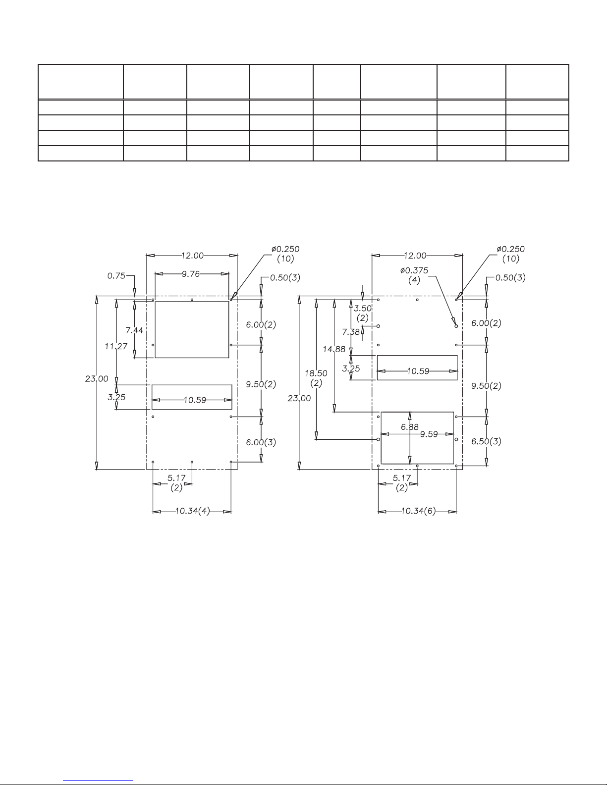
TX23 Mounting Cutout Dimensions ................................................................................................................................................... 5
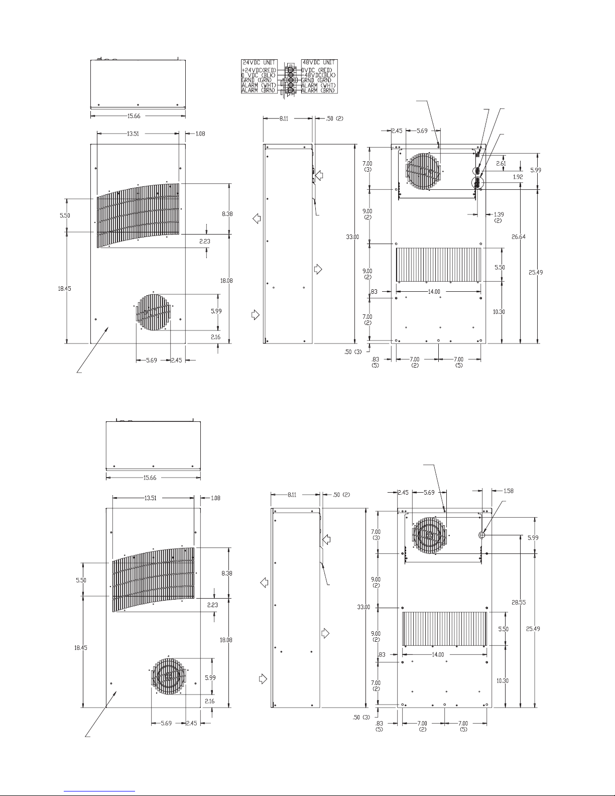
TX23 DC Model Drawing ........................................................................................................................................................................ 6
TX23 AC Model Drawing ......................................................................................................................................................................... 6
TX33 Series ................................................................................................................................................................................................... 7
TX33 Mounting Cutout Dimensions ................................................................................................................................................... 7
TX33 DC Model Drawing ........................................................................................................................................................................ 8
TX33 AC Model Drawing ......................................................................................................................................................................... 8
TX38 Series ................................................................................................................................................................................................... 9
TX38 Mounting Cutout Dimensions ................................................................................................................................................... 9
TX38 DC Model Drawing ......................................................................................................................................................................10
TX38 AC Model Drawing .......................................................................................................................................................................10
TX52 Series .................................................................................................................................................................................................11
TX52 Mounting Cutout Dimensions .................................................................................................................................................11
TX52 DC Model Drawing ......................................................................................................................................................................12
TX52 AC Model Drawing .......................................................................................................................................................................12
TX23 Components List ..........................................................................................................................................................................13
TX33 Components List ..........................................................................................................................................................................13
TX38 Components List ..........................................................................................................................................................................13
TX52 Components List ..........................................................................................................................................................................13
TX DC Wire Diagram (see label on unit for actual options) ......................................................................................................14
TX23 AC Wire Diagram (see label on unit for actual options) .................................................................................................15
TX33, TX38, TX52 AC Wire Diagram (see label on unit for actual options) .........................................................................15
TROUBLE SHOOTING AC Units ....................................................................................................................................................................16
Basic Trouble Shooting Check List .....................................................................................................................................................16
TROUBLE SHOOTING DC Units ...................................................................................................................................................................17
Basic Trouble Shooting Check List .....................................................................................................................................................17
WARRANTY ........................................................................................................................................................................................................18
RETURN AND REPAIR POLICY ......................................................................................................................................................................18
LIMITATION OF LIABILITY ..............................................................................................................................................................................19

© 2011 Pentair Technical Products87976519 - 3 -
RECEIVING THE AIR CONDITIONER
Inspect the Heat Exchanger. Check for concealed damage that may have occurred during shipment. Look for dents,
scratches, loose assemblies, etc. Damage evident upon receipt should be noted on the freight bill. Damage should
be brought to the attention of the delivering carrier -- NOT to McLean Thermal -- within 15 days of delivery. Save the
carton and packing material and request an inspection. Then le a claim with the delivering carrier.
Pentair Technical Products cannot accept responsibility for freight damages; however, we will assist you in any way
possible.
TESTING THE HEAT EXCHANGER
TEST FOR FUNCTIONALITY BEFORE MOUNTING THE HEAT EXCHANGER TO THE ENCLOSURE.
Refer to nameplate for proper electrical current requirements, and then connect power cord to a properly grounded
power supply. Minimum circuit ampacity should be at least 125% of the amperage shown in the design data section
for the appropriate model. No other equipment should be connected to this circuit to prevent overloading.
Operate the heat exchanger for several minutes. No excessive noise or vibration should be evident during this run
period. Ambient air mover may not be energized at temperatures low enough to not require cooling. On DC powered
units, air movers may not always be running at full speed.

© 2011 Pentair Technical Products 87976519
- 4 -
INSTALLATION INSTRUCTIONS
1. Inspect heat exchanger. Verify functionality before mounting the heat exchanger, see TESTING THE
HEAT EXCHANGER on page 3.
2. Determine if the unit is to be surface or recess mounted. Using the appropriate cutout dimensions
shown in this manual, prepare the enclosure opening for either surface or recess mounting.
3. Using the gasket kit provided, install gaskets to heat exchanger.
4. Mount heat exchanger on enclosure using mounting screws provided. Torque screws to 25 in-lbs (2.82
Nm).
5. Refer to unit nameplate for electrical requirements. Connect the power cord to a properly grounded
power supply. Use of an extension cord is not recommended. Electrical circuit should be fused with
slow blow or HACR circuit breaker.
PRINCIPLES OF OPERATION
Operating the heat exchanger below the minimum ambient temperature or above the maximum ambient
temperatures indicated on the nameplate voids all warranties.
It is recommended that the warranty section of this manual be read in order to familiarize yourself with parameters of
restricted operation.
MAINTENANCE
Air Movers
Air mover motors require no maintenance. All bearings are lubricated during manufacturing for the life of the motor.
If the ambient air mover should fail, it is not necessary to remove the heat exchanger from the cabinet or enclosure to
replace it. The ambient air mover is mounted on a bulkhead and is easily accessible by removing the front cover.
Caution! Operation of the heat exchanger in areas containing airborne caustics or chemicals can rapidly deteriorate
aluminum cores and air movers. Contact Pentair Technical Products for special recommendations.
Ambient Air In/Out Screens
In dirty environments, the bug screens on the front cover may need to be cleaned periodically to maintain adequate
cooling performance. The front cover should be removed from the heat exchanger and set aside for cleaning with
water, air or scrubbed clean with a brush.

© 2011 Pentair Technical Products87976519 - 5 -
TX23 Series
25 Watts/°C (14 Watts/°F)
Model Voltage Hz Full Load
Amps Phase
Maximum
Temperature
(°C/°F)
Minimum
Temperature
(°C/°F)
Shipping
Weight
(lb./kg)
TX23-1424-XXX 24VDC 3.4 65/149 -40/-40 30/13.6
TX23-1448-XXX 48VDC 1.8 65/149 -40/-40 30/13.6
TX23-1416-XXX 115VAC 50/60 TBD 1 65/149 -40/-40 30/13.6
TX23-1426-XXX 230VAC 50/60 TBD 1 65/149 -40/-40 30/13.6
XXX will be replaced with a three-digit number designating all desired options. Consult the factory for specic model numbers.
TX23 Mounting Cutout Dimensions
External Mounting Internal Mounting
CUTOUT INSTRUCTIONS
(As viewed from outside of enclosure)
NOTE: Dashed lines represent heat exchanger.

© 2011 Pentair Technical Products 87976519
- 6 -
TX23 DC Model Drawing
TX23 AC Model Drawing
AMBIENT
AIR OUT
ENCLOSURE
AIR OUT
MOUNTING HARDWARE FOR FULLY RECESSED
MOUNTING IS BEHIND REMOVEABLE FRONT COVER.
REMOVEABLE
HANGING
TABS (2)
#10-24 MOUNTING (20)
(10 ON BACK FACE - 10
BEHIND FRONT COVER)
DETAIL “A”
SCALE .500
AMBIENT
AIR IN
ENCLOSURE
AIR IN
CONTROLLER
LED’S
AC HEATER
POWER
SEE DETAIL “A”
IMPELLER POWER AND
ALARM INTERFACE
AMBIENT
AIR OUT
ENCLOSURE
AIR OUT
MOUNTING HARDWARE FOR FULLY RECESSED
MOUNTING IS BEHIND REMOVEABLE FRONT COVER.
REMOVEABLE
HANGING
TABS (2)
#10-24 MOUNTING (20)
(10 ON BACK FACE - 10
BEHIND FRONT COVER)
AMBIENT
AIR IN
ENCLOSURE
AIR IN
POWER CORD
ENTRANCE

© 2011 Pentair Technical Products87976519 - 7 -
TX33 Series
50 Watts/°C (28 Watts/°F)
Model Voltage Hz Full Load
Amps Phase
Maximum
Temperature
(°C/°F)
Minimum
Temperature
(°C/°F)
Shipping
Weight
(lb./kg)
TX33-2824-XXX 24VDC 3.4 65/149 -40/-40 45/20.4
TX33-2848-XXX 48VDC 1.8 65/149 -40/-40 45/20.4
TX33-2816-XXX 115VAC 50/60 TBD 1 65/149 -40/-40 45/20.4
TX33-2826-XXX 230VAC 50/60 TBD 1 65/149 -40/-40 45/20.4
XXX will be replaced with a three-digit number designating all desired options. Consult the factory for specic model numbers.
TX33 Mounting Cutout Dimensions
External Mounting Internal Mounting
CUTOUT INSTRUCTIONS
(As viewed from outside of enclosure)
NOTE: Dashed lines represent heat exchanger.

© 2011 Pentair Technical Products 87976519
- 8 -
TX33 DC Model Drawing
TX33 AC Model Drawing
AMBIENT
AIR OUT
ENCLOSURE
AIR OUT
MOUNTING HARDWARE FOR FULLY RECESSED
MOUNTING IS BEHIND REMOVEABLE FRONT COVER.
REMOVEABLE
HANGING
TABS (2)
#10-24 MOUNTING (24)
(12 ON BACK FACE - 12
BEHIND FRONT COVER)
DETAIL “A”
SCALE .500
AMBIENT
AIR IN
ENCLOSURE
AIR IN
CONTROLLER
LED’S
AC HEATER
POWER
SEE DETAIL “A” IMPELLER
POWER AND ALARM
INTERFACE
AMBIENT
AIR OUT
ENCLOSURE
AIR OUT
MOUNTING HARDWARE FOR FULLY RECESSED
MOUNTING IS BEHIND REMOVEABLE FRONT COVER.
REMOVEABLE
HANGING
TABS (2)
#10-24 MOUNTING (24)
(12 ON BACK FACE - 12
BEHIND FRONT COVER)
AMBIENT
AIR IN
ENCLOSURE
AIR IN
POWER CORD
ENTRANCE

© 2011 Pentair Technical Products87976519 - 9 -
TX38 Series
100 Watts/°C (56 Watts/°F)
Model Voltage Hz Full Load
Amps Phase
Maximum
Temperature
(°C/°F)
Minimum
Temperature
(°C/°F)
Shipping
Weight
(lb./kg)
TX38-5624-XXX 24VDC 8.6 65/149 -40/-40 66/30
TX38-5648-XXX 48VDC 5.8 65/149 -40/-40 66/30
TX38-5616-XXX 115VAC 50/60 TBD 1 65/149 -40/-40 66/30
TX38-5626-XXX 230VAC 50/60 TBD 1 65/149 -40/-40 66/30
XXX will be replaced with a three-digit number designating all desired options. Consult the factory for specic model numbers.
TX38 Mounting Cutout Dimensions
External Mounting Internal Mounting
CUTOUT INSTRUCTIONS
(As viewed from outside of enclosure)
NOTE: Dashed lines represent heat exchanger.

© 2011 Pentair Technical Products 87976519
- 10 -
TX38 DC Model Drawing
TX38 AC Model Drawing
AMBIENT
AIR OUT
ENCLOSURE
AIR OUT
MOUNTING HARDWARE FOR FULLY RECESSED
MOUNTING IS BEHIND REMOVEABLE FRONT COVER.
REMOVEABLE
HANGING
TABS (2)
#10-24 MOUNTING (28)
(14 ON BACK FACE - 14
BEHIND FRONT COVER)
DETAIL “A”
SCALE .500
AMBIENT
AIR IN
ENCLOSURE
AIR IN
CONTROLLER
LED’S
AC HEATER
POWER
SEE DETAIL “A”
IMPELLER POWER
AND ALARM
INTERFACE
AMBIENT
AIR OUT
ENCLOSURE
AIR OUT
MOUNTING HARDWARE FOR FULLY RECESSED
MOUNTING IS BEHIND REMOVEABLE FRONT COVER.
REMOVEABLE
HANGING
TABS (2)
#10-24 MOUNTING (28)
(14 ON BACK FACE - 14
BEHIND FRONT COVER)
AMBIENT
AIR IN
ENCLOSURE
AIR IN
POWER CORD
ENTRANCE

© 2011 Pentair Technical Products87976519 - 11 -
TX52 Series
150 Watts/°C (83 Watts/°F)
Model Voltage Hz Full Load
Amps Phase
Maximum
Temperature
(°C/°F)
Minimum
Temperature
(°C/°F)
Shipping
Weight
(lb./kg)
TX52-8324-XXX 24VDC 21.1 65/149 -40/-40 100/45.3
TX52-8348-XXX 48VDC 7.8 65/149 -40/-40 100/45.3
TX52-8316-XXX 115VAC 50/60 4.3/6.7 1 65/149 -40/-40 100/45.3
TX52-8326-XXX 230VAC 50/60 2.2/3.4 1 65/149 -40/-40 100/45.3
XXX will be replaced with a three-digit number designating all desired options. Consult the factory for specic model numbers.
TX52 Mounting Cutout Dimensions
External Mounting Internal Mounting
CUTOUT INSTRUCTIONS
(As viewed from outside of enclosure)
NOTE: Dashed lines represent heat exchanger.

© 2011 Pentair Technical Products 87976519
- 12 -
TX52 DC Model Drawing
TX52 AC Model Drawing
AMBIENT
AIR OUT
ENCLOSURE
AIR OUT
MOUNTING HARDWARE FOR FULLY RECESSED
MOUNTING IS BEHIND REMOVEABLE FRONT COVER.
REMOVEABLE
HANGING
TABS (2)
#10-24 MOUNTING (32)
(16 ON BACK FACE - 16
BEHIND FRONT COVER)
DETAIL “A”
SCALE .500
AMBIENT
AIR IN
ENCLOSURE
AIR IN
CONTROLLER
LED’S AC HEATER
POWER
SEE DETAIL “A” IMPELLER
POWER AND ALARM
INTERFACE
AMBIENT
AIR OUT
ENCLOSURE
AIR OUT
MOUNTING HARDWARE FOR FULLY RECESSED
MOUNTING IS BEHIND REMOVEABLE FRONT COVER.
REMOVEABLE
HANGING
TABS (2)
#10-24 MOUNTING (32)
(16 ON BACK FACE - 16
BEHIND FRONT COVER)
AMBIENT
AIR IN
ENCLOSURE
AIR IN
POWER CORD
ENTRANCE

© 2011 Pentair Technical Products87976519 - 13 -
TX23 Components List
Part Description Part Number
24VDC 48VDC 115VAC 230VAC
Air Movers 10-1091-64 10-1091-55 12-1012-01 12-1012-02
Controller, Generic (may vary w/options) E117E004 E117E004 NA NA
Thermostat NA NA 10-1061-16 10-1061-16
Service Cord / Harness 09-3001-89 09-3001-89 52-6035-138 52-6035-139
TX33 Components List
Part Description Part Number
24VDC 48VDC 115VAC 230VAC
Air Movers 10-1091-64 10-1091-55 10-1091-130 10-1091-131
Controller, Generic (may vary w/options) E117E004 E117E004 NA NA
Thermostat NA NA 10-1061-16 10-1061-16
Capacitors NA NA S-1353-1 52-6084-02
Service Cord / Harness 09-3001-89 09-3001-89 52-6035-138 52-6035-139
TX38 Components List
Part Description Part Number
24VDC 48VDC 115VAC 230VAC
Air Movers 10-1091-12 10-1091-109 10-1091-132 10-1091-133
Controller, Generic (may vary w/options) E117E000 E117E000 NA NA
Thermostat NA NA 10-1061-16 10-1061-16
Capacitors NA NA 52-6031-03 52-6084-05
Service Cord / Harness 09-3001-89 09-3001-89 52-6035-138 52-6035-139
TX52 Components List
Part Description Part Number
24VDC 48VDC 115VAC 230VAC
Air Movers 10-1091-125 10-1091-126 10-1091-134 10-1091-135
Controller, Generic (may vary w/options) E117E002 E117E006 NA NA
Thermostat NA NA 10-1061-16 10-1061-16
Capacitors NA NA 52-6031-03 52-6084-05
Service Cord / Harness 09-3001-96 09-3001-89 52-6035-138 52-6035-139

© 2011 Pentair Technical Products 87976519
- 14 -
TX DC Wire Diagram (see label on unit for actual options)
GROUND
ALARM
LOOP
INTERNAL
IMPELLER
EXTERNAL
IMPELLER
CONTROLLER
ON
NOTE: SWITCH SETTINGS

© 2011 Pentair Technical Products87976519 - 15 -
TX23 AC Wire Diagram (see label on unit for actual options)
TX33, TX38, TX52 AC Wire Diagram (see label on unit for actual options)
SERVICE
CORE
INTERNAL
FAN
EXTERNAL
FAN
THERMOSTAT
SERVICE
CORE
RUN
CAPACITOR
RUN
CAPACITOR
INTERNAL
IMPELLER
EXTERNAL
IMPELLER
THERMOSTAT

© 2011 Pentair Technical Products 87976519
- 16 -
TROUBLE SHOOTING AC Units
Basic Trouble Shooting Check List
1. Check manufacturer’s nameplate located on the unit for correct power supply.
2. Unit blows fuses or breakers.
• Under sized fuse/breaker or not time delayed
• Short in system
Repair or Replace
defective part
3. Turn on power to the unit. The enclosure air mover should come on. Is there airow?
YES, proceed to step 4.
NO, possible problem:
• Open motor winding
• Stuck air mover motor
• Obstructed wheels/blades
Repair or Replace
defective part
4. Check thermostat setting? Adjust thermostat to the lowest setting. This should turn both air movers
on. Did both air movers come on when the thermostat was turned down?
YES, proceed to step 5.
NO, possible problem:
• Defective thermostat Replace part
5. Are both air movers running? If not, the unit will not cool properly.
6. Check ambient air mover for airow. Is there airow?
YES, proceed to step 7.
NO, possible problem:
• Defective thermostat
• Open motor winding
• Stuck air mover motor
• Obstructed wheels/blades
Repair or Replace
defective part
7. To check for a bad thermostat, turn o power to the unit. Remove access cover and place both
thermostat wires onto one terminal (replace access cover for safety). This will bypass the switch in the
thermostat. Turn on power to the unit and if both air movers come on, the thermostat needs to be
replaced.
For additional technical information (i.e., amp draw, temperatures) , contact Pentair Technical
Products at 800-896-2665.

© 2011 Pentair Technical Products87976519 - 17 -
TROUBLE SHOOTING DC Units
Basic Trouble Shooting Check List
1. Check manufacturer’s nameplate located on the unit for correct power supply.
2. Unit blows fuses or breakers.
• Under sized fuse/breaker or not time delayed
• Short in system
Repair or Replace
defective part
3. Turn on power to the unit.
4. Press the Quick-Test button (located above the LED’s on the enclosure side of the unit). The unit will
cycle through a series of self-diagnostic tests to verify proper operation of components.
5. Do all LED’s clear to GREEN following the self test? RED indicates a fault.
YES, unit is working properly.
NO, identify which alarm is activated:
Note the Composite Alarm LED will also light if any other alarm activates.
• Ambient air mover
OR
Enclosure air mover
• Open motor winding
• Stuck air mover motor
• Obstructed blades
Repair or Replace
defective part
• Hi / Lo Temperature • If the enclosure temperature is outside the nameplate temperature
range, the Hi / Lo Temperature alarm will activate.
• Composite Alarm Only • Controller Temperature Sensor Failure Repair or Replace
defective part
For additional technical information (i.e., amp draw, temperatures) , contact Pentair Technical
Products at 800-896-2665.
Quick-Test Button
Hi / Lo Temperature LEDComposite Alarm LED
Enclosure Fan LEDAmbient Fan LED

© 2011 Pentair Technical Products 87976519
- 18 -
WARRANTY
Pentair Technical Products warrants that the Goods manufactured by Pentair Technical Products will be free
from defects in material and workmanship for a period of one (1) year from the date of shipment by Pentair
Technical Products, subject to the following conditions and exclusions:
A. Conditions. All Goods must be installed and operated according to the following specications:
1. Maximum voltage variation no greater than plus or minus 10% of nameplate nominal rating;
2. Maximum frequency variation no greater than plus or minus 3 Hz. of nameplate nominal rating;
3. Must not exceed minimum and maximum stated temperatures on the nameplate;
4. Must not exceed (BTU/Hr) rating, including any heat sink as indicated on the nameplate;
5. Refrigerant bearing Goods must not be restarted for a period of one (1) minute after intentional or
accidental shut-o;
6. The lters (if applicable) must be cleaned regularly;
7. The Goods and any parts thereof must not be modied, unless prior written authorization is received
from Pentair Technical Products; and
8. All Goods must be installed and grounded in accordance with all relevant electrical and safety codes,
as well as the National Electric Code and OSHA rules and regulations.
9. All Goods must be installed in a stationery application, free of vibration.
A violation of any one of these conditions shall render the warranty hereunder void and of no eect.
B. Exclusions. This warranty shall be void if product is misapplied in any way or:
1. Buyer specied product is inappropriate for system or environment in which it is operating.
2. Pentair Technical Products product modied in any way without prior written authorization from
Pentair Technical Products.
3. Removal or modication of Pentair Technical Products label axed to product without written Pentair
Technical Products approval.
Pentair Technical Products must be notied of a claim in writing not later than fourteen (14) days from the
date when Buyer has become aware of such occurrence, or where the defect is such that it may cause damage,
immediately, such notice containing a description of how the defect manifests itself. Failure to provide such
prompt notice to Pentair Technical Products shall result in forfeiture of Buyer’s rights under this warranty.
In the event of a warranty claim, Buyer is to return defective goods to Pentair Technical Products in accordance
with Pentair Technical Products Return Policy. Warranty period for repaired goods remains at 1 year from
shipment of original goods. Pentair Technical Products sole obligation to Buyer under this warranty will be, at
Pentair Technical Products option:
A. Repair or replace Pentair Technical Products products or parts found to be defective in material or
workmanship.
B. Issue credit for the purchase price paid by Buyer relating to such defective Goods or part.
THIS WARRANTY CONSTITUTES THE ENTIRE WARRANTY WITH RESPECT TO THE GOODS AND IS IN LIEU OF ALL
OTHER WARRANTIES, EXPRESSED OR IMPLIED, INCLUDING ANY IMPLIED WARRANTY OF MERCHANTABILITY
AND IMPLIED WARRANTY OF FITNESS FOR A PARTICULAR PURPOSE.
RETURN AND REPAIR POLICY
Pentair Technical Products products that: (i) are made to order, (ii) have been modied by Buyer, (ii) have
special nishes, or (iv) are determined by Pentair Technical Products to constitute “custom” products that
cannot be returned to stock or resold to other Buyers, will not be accepted for return by Pentair Technical
Products.
All returns require a Return Material Authorization number (RMA #), regardless of reason for return, whether
it be for warranty or out of warranty repair. Returns without an RMA # will be refused by our Receiving
Department. An RMA # is valid for 60 days.
A. An RMA # will be issued by our Repair Department in Anoka, MN at 866-545-5252. Buyer should have
following information available at time of RMA request:

© 2011 Pentair Technical Products87976519 - 19 -
1. Complete Model Number, Serial Number and description of damaged unit being returned.
2. Original Buyer Purchase Order number and date product was received by Buyer.
3. Quantity to be returned and a brief description of failure for each unit, if dierent.
4. Contact information of Buyer that must include: name of company, billing and shipping address,
phone, number, fax number, freight carrier and the name and phone number of a Buyer contact who
can elaborate on the claimed defect in detail.
5. Buyer must provide a Repair Purchase Order number for both warranty and out of warranty repairs.
The PO will not exceed 50% of a new unit. Buyer will be notied of repair charges that exceed
approved PO amount.
B. All returns to Pentair Technical Products must be securely packed, using original cartons if possible. All
returns must have the RMA number visible on the outside of the carton. Pentair Technical Products is not
responsible for material damaged in transit. Any refrigerant-bearing Goods must be shipped upright for
return.
C. Shipping cost for all non-warranty repairs is the responsibility of the sender and must be shipped prepaid.
Shipping costs for all warranty related repairs will be covered by Pentair Technical Products provided the
goods are returned using a Pentair Technical Products approved carrier. If after diagnoses the product is
determined by Pentair Technical Products not be covered under warranty, Buyer will be responsible for all
shipping charges and will be billed accordingly.
D. Non-warranty repairs are subject to a $75 minimum analysis fee. Analysis fee will be waived if Buyer
approves repair work. If approval is not received within 30 days, material will be scrapped and all shipping
expenses and corresponding analysis fees will be billed to Buyer.
E. At Buyer’s request, Failure Analysis can be provided by Pentair Technical Products for warrantable goods at
no charge. Failure analysis for non-warranty repairs are subject to a $100 per hour Engineering charge plus
any other incurred testing costs.
F. All returned merchandise must be sent to the following address: Pentair Technical Products, 2100 Homan
Way, Anoka, MN 55303-1745.
G. Credit for accepted returns shall be at the original selling price or the current selling price, whichever is
lower, less the restocking charge indicated as follows:
1. Within 60 days of invoice date - 20% of applicable selling price.
2. Within 61-120 days of invoice date - 30% of applicable selling price.
3. Within 121-180 days of invoice date - 40% of applicable selling price.
4. Beyond 180 days - subject to individual review by Pentair Technical Products.
If product being returned for credit requires repair or modication, the cost of any labor or material necessary
to bring product into saleable condition will be deducted from credit. Buyer may not take credit against
returns without prior written Pentair Technical Products approval.
LIMITATION OF LIABILITY
PENTAIR TECHNICAL PRODUCTS WILL NOT BE LIABLE UNDER ANY CIRCUMSTANCES FOR ANY INCIDENTAL,
CONSEQUENTIAL OR SPECIAL DAMAGES, INCLUDING WITHOUT LIMITATION ANY LOST PROFITS OR
LABOR COSTS, ARISING FROM THE SALE, USE OR INSTALLATION OF THE GOODS, FROM THE GOODS BEING
INCORPORATED INTO OR BECOMING A COMPONENT OF ANOTHER PRODUCT, FROM ANY BREACH OF THIS
AGREEMENT OR FROM ANY OTHER CAUSE WHATSOEVER, WHETHER BASED ON WARRANTY (EXPRESSED
OR IMPLIED) OR OTHERWISE BASED ON CONTRACT, OR ON TORT OR OTHER THEORY OF LIABILITY, AND
REGARDLESS OF ANY ADVICE OR REPRESENTATIONS THAT MAY HAVE BEEN RENDERED BY PENTAIR TECHNICAL
PRODUCTS CONCERNING THE SALE, USE OR INSTALLATION OF THE GOODS

© 2011 Pentair Technical Products 87976519
Rev. F P/N 10-1008-221
Protecting Electronics.
Exceeding Expectations.™
Pentair Technical Products
2100 Homan Way
Anoka, MN 55303
+1-763-323-8200
+1-763-576-3200
www.McLeanCoolingTech.com
This manual suits for next models
3
Table of contents
Popular Heat Pump manuals by other brands

Panasonic
Panasonic WH-MDC09G3E5 Service manual

Carrier
Carrier 50PEC09-18 Aquazone Installation, Start-Up and Service Instructions

Lennox
Lennox 16ACX Series Unit information

FHP
FHP HR000 installation manual

ECOFOREST
ECOFOREST ecogeo basic Technical & service manual

ClimateMaster
ClimateMaster Tranquility TCH Series Installation operation & maintenance

OEG
OEG 650 001 330 Installation and operating instruction

Carrier
Carrier 80AWX Series installation manual

York
York TH4 Series installation manual

evoheat
evoheat Evo315-C Installation and operation manual

Lennox
Lennox HP29-090 installation instructions

Danfoss
Danfoss Optyma Slim Pack OP-LPQE Series instructions