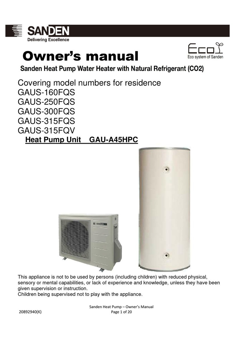
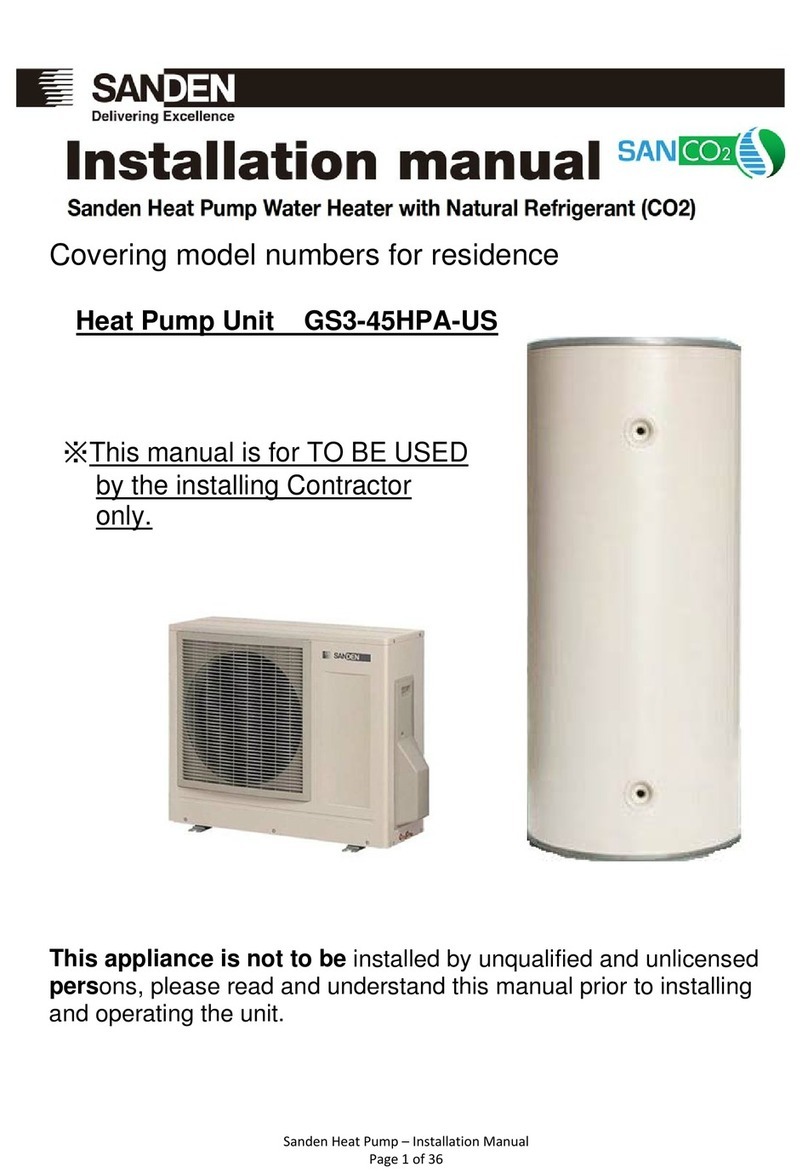
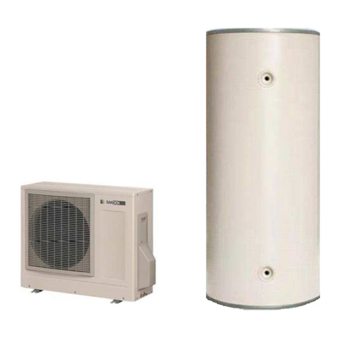
Sanden GAUS-315QS User manual

Sanden Heat Pump – Owner’s Manual
Page 1 of 20
Covering model numbers for residence
GAUS-315QT
GAUS-315QS
GAUS-250EQTB
GAUS-160EQTB
Heat Pump Unit GS3-45HPA-AU
This appliance is not to be used by persons (including children) with reduced physical,
sensory or mental capabilities, or lack of experience and knowledge, unless they have been
given supervision or instruction.
Children being supervised not to play with the appliance.
Owner’s
m
anual

Sanden Heat Pump – Owner’s Manual
Page 2 of 20
Contents
Page title..............................................................................................................................1
Contents ..............................................................................................................................2
Introduction..........................................................................................................................3
How it works ........................................................................................................................3
Installation details................................................................................................................8
Trouble shooting guide ........................................................................................................9
Error Codes .......................................................................................................................10
Removing air from the system...........................................................................................11
Electrical connections........................................................................................................12
System operation outline continuous power ......................................................................12
System operation if connected to off-peak electricity.........................................................12
How to connect power line.................................................................................................13
Water supply Quality..........................................................................................................14
Change of water supply.....................................................................................................14
Technical data ...................................................................................................................15
Warranty Policy..................................................................................................................17
Warranty Period.................................................................................................................18
Registration for warranty....................................................................................................19
PATENTS
This water heater may be protected by one or more patents or registered designs
in the name of Sanden Australia Pty Ltd
TRADE MARKS
® Registered trademark of Sanden Australia Pty Ltd
.
Note: Every care has been taken to ensure accuracy in preparation of this publication.
No liability can be accepted for any consequences that may arise as a result of its application No liability can be
accepted for any consequences that may arise as a result of its application. Sanden is in a process of
continuous improvement with, therefore specifications may be different to those referenced in this manual –
Please contact Sanden International or it’s distributors for the latest specifications at the time of install.

Sanden Heat Pump – Owner’s Manual
Page 3 of 20
Introduction
The Sanden Heat Pump Water Heater System has been designed using the latest
refrigeration technology to remove the heat from the air to heat water. The refrigerant we
use is CO
2
which does not contribute to global warming so it allows us to help keep a clean
healthy earth for future generations.
We have also considered the power requirement. By using CO
2
as the refrigerant we have
produced one of the most energy efficient units currently available. It’s even more efficient
when connected to off-peak power
and the noise level is so low it will operate
unobtrusively throughout the night.
How it works
The Heat Pump Water Heater System heats water by transferring the heat from the
surrounding air to the water using a refrigerant. The refrigerant is heated by a heat
exchanger that absorbs heat from the surrounding air (Figure 1).
Figure 1: Heat Pump Water Heater System
Note
Operating conditions may vary depending on the type of off peak tariff that is available in
your area. The unit must have a minimum of 5 hours continuous power available at all time
to allow the unit to operate without affecting reliability.

Sanden Heat Pump – Owner’s Manual
Page 4 of 20

Sanden Heat Pump – Owner’s Manual
Page 5 of 20
LPG

Sanden Heat Pump – Owner’s Manual
Page 6 of 20
Check the installation conditions of the unit.
Installat on of the un t n the follow ng places could result
n acc dents or fa lure and the performance of the un t
not be ng guaranteed.
· Anywhere the lowest temperature reached s under
m nus 20 degrees cent grade
· Indoors (Appl es only to the heat pump un t)
· Anywhere not completely flat, unstable or where
dra nage s d ff cult
· Ensure not to put anyth ng around the heat pump un t.
Could result n poor performance and unexpected
problems.
In the w nter n part cular please pay attent on to any
snow coverage.

Sanden Heat Pump – Owner’s Manual
Page 7 of 20

Sanden Heat Pump – Owner’s Manual
Page 8 of 20
Installation details
This Sanden Eco Hot water Heat Pump System must be installed by a licensed person in
consideration of the following standards and regulations:
AS/NZS3500 National plumbing and drainage code hot water supply systems –
acceptable solutions
HB 263-2004 Heated water systems plumbing industry commission
AS/NZS 3000 Electrical installations (known as the Australian/New Zealand wiring
rules)
Notice to Victorian customers from the Victorian Plumbing Industry Commission.
The Victorian Building Act 1993 requires that this Heat Pump Water Heater System
must be installed by a licensed person. Only a licensed person will provide a
Compliance Certificate, showing that the work complies with all the relevant
standards. Only a licensed person will have insurance protecting their workmanship
for six years.
The unit has been specifically designed for domestic hot water heating and is not
suitable for any other purpose.
The unit is designed to operate when connected to the town water supply with a
maximum operating pressure of 500 kPa. To ensure the mains pressure does not
exceed this, a pressure-limiting device that complies with AS1357 must be
connected to the town water supply line.
This system delivers hot water exceeding 50
o
C. Reference should be made to
AS/NZ3500 and/or local regulations relating to the need for temperature tempering
devices.
The unit must be stored and transported in an upright position. Failure to do so may
render the unit faulty. Such failure is not covered under any warranty agreements.
Failure to comply with the above conditions will void the warranty.
Figure 2: Typical installation layout
Pressure Reducer Valve
500kPa

Sanden Heat Pump – Owner’s Manual
Page 9 of 20
Trouble shooting guide
If you faced to a problem in a use of our heat pump water heater system, please check the
following things prior to calling for a support.
For those problems not listed in the list above, an inspection provided by a skilled engineer
is required. Please contact the distributor.
Caution:
Do not shut the electricity supplied to the heat pump system even if you go away from
home and do not use hot water for a long while.
If the system is equipped with freeze protect heaters, also do not shut the power supply to
the heaters.
Failure to do so may cause a crack on the pipes due to the pipes getting frozen.
Status Considerable Causes Action to Take
No hot water
comes out of
water tap
Temperature
of hot water is
too low
Small or no hot water is left in
the storage tank.
- Stop using hot water and wait for about 1
hour
- Consider a change of the electricity
supply off-peak mode (Length of power-
supply hours may be too short for the
water heating cycle to cover the hot water
consumption)
Air removing procedure from the
heat pump system may be
insufficient.
- Open the water drain plugs on the Heat
Pump Unit to remove air from water circuit.
(Be careful for burning)
Filter on cold inlet connector may
be blocked. - Check the filter and remove if there is any
blockage
Water flow speed may be
dropped due to the heat pump
piping bend, blockage or crush.
- Check for any piping bend or crush and
remove if any
Pipes may be frozen. - If frozen area is found on the piping, melt
the ice on the pipe and provide a heat
insulation
Stop valve is closed. - Open the valve
Air absorption is not sufficient
due to a blockage on the
evaporator.
-Remove the object being blocking the air
flow through the evaporator
(e.g. fallen leaves, grass, snow, etc.)

Sanden Heat Pump – Owner’s Manual
Page 10 of 20
Error Codes
When an error has occurred, a red LED on the operation panel turns on and an error code
is displayed on the LED display. The panel does not turn to the display sleep mode while
the error code is shown.
Figure 3 Error Code example
Below is the list of the error codes. If the corrective action does not solve the error problem,
a malfunction of the PCB is highly likely.
Error
code Error contents
Error
code Error contents
E001 HP water outlet over
temperature 1 E015 HP ambient temperature
thermistor wire break
E002 HP water outlet over
temperature 2 E016 Tank thermistor wire break
E003 HP outlet temperature thermistor
detection error E021 HP inlet temperature thermistor
wire short circuit
E004 HP discharge over temperature
1 E022 HP outlet temperature thermistor
wire short circuit
E005 HP discharge over temperature
2 E023 HP discharge temperature
thermistor wire short circuit
E006 HP discharge temperature
Thermistor detection error E024 HP defrost temperature
thermistor wire short circuit
E007 High pressure side error E025 HP ambient temperature
thermistor wire short circuit
E008 High ambient temperature
defrost drive error E026 Tank thermistor short circuit
E009 HP defrost thermistor detection
error E031 Fan motor locked
E011 HP inlet temperature thermistor
wire break E032 Fan motor revolution error
E012 HP outlet temperature thermistor
wire break E034 Water circulation pump locked
E013 HP discharge temperature
thermistor wire break
E040
~
E089 System control error
E014 HP defrost temperature
thermistor wire break

Sanden Heat Pump – Owner’s Manual
Page 11 of 20
Removing air from the system
•The following steps must be taken to ensure all air is removed from the system.
Incorrect removal of air may cause the water temperature to vary.
•Plumb pipes to the tank unit and the heat pump unit.
•Push up the lever on the PTR valve to open, and fill the tank unit with water.
•Confirm that the water comes out of the relief valve and then close the lever.
•Open the hot water taps in the home to remove air.
•Close the hot water taps in the home after no air is confirmed in the water.
•Open the water drain plugs (two places) on the heat pump unit.
•Close the plugs after no air is confirmed in the water.
•Connect the power to the heat pump unit and leave a hot water tap open in the
home for three minutes.
•Close the house hot water tap after no air is confirmed in the water.
Figure 4: Air removing process
Plumb pipes to Storage Tank Unit and Heat Pump Unit.
Push up the lever on the PTR valve to open,
and fill in the tank with water.
Confirm the water come out of the relief valve,
and then close the lever.
Water drain plugs
Open the faucet to remove air. Close the faucet
after no air bubbles can be seen in the water.
Open the water drain plugs (2 places) on the Heat Pump
Unit. Close the plugs after no air is confirmed in the water
supply.
Then connect power to the Heat Pump Unit. Open
Faucets.
PTR valve lever

Sanden Heat Pump – Owner’s Manual
Page 12 of 20
Electrical connections
•Electrical installation should be done only by a licensed electrician who carries out
the work according to the relevant regulations for electrical safety and wiring.
•Follow the wiring rules for the breaker rating and the thickness of the electrical
wiring.
•Verify that the tank unit is full of water and the water stop cocks are open before
turning on the power.
System operation outline continuous power
The system runs its water heating cycle once a day to fill up the storage tank unit with
heated water.
If the block out time function is selected ( setting is covered in page 17 of Installation
Manual ) the unit will not operate during the block out times – this function is typically
used on installations that have time of use electricity tariffs
The water heating cycle operation starts automatically when the residual hot water in
the tank unit becomes less than 150 litres.
The system will not run if the electrical power supply is cut off (i.e. if it is connected to
off-peak power). However, the system will automatically start operation, once the
electricity becomes available.
System operation if connected to off-peak electricity
There are no special settings for the off-peak connection. The system will run once the
power becomes available and the temperature in the tank drops below the set point of
the tank thermistor. If connecting the unit to off-peak, ensure that the off-peak tariff
provides a minimum of 5 hours continuous power, as it can take at least four hours to
fill the tank unit with hot water if the ambient temperature is lower than 10
o
C, this can
be longer.
If the unit is connected to off-peak and consumption has been higher than normal hot
water might not be available until the next power supply cycle.
Daily frequency and amount of hot water consumption may also affect the duration of
the heating cycle operation.
Select the electrical supply mode that best suits the customer’s hot water
consumption. The type of off-peak connection may need to be changed if hot water
supply is not maintained as required.
Figure 5: Outline of electrical system connections
Caut on
Use Copper w r ng

Sanden Heat Pump – Owner’s Manual
Page 13 of 20
How to connect power line
Please note:
Electrical installation should only be done by a licensed electrician
Remove the piping cover, terminal block cover and screw clamp fitting.
Connect the power supply line to the terminal block.
Hold the power supply line below the terminal block with the screw clamp fitting.
Attach the terminal block cover and piping cover back on the heat pump unit.
Figure 6: Connect power cables
Power supply
W re holder band
Power l ne
Ground
Green
Wh te
Black
3×M4 Screws
L N
N
L

Sanden Heat Pump – Owner’s Manual
Page 14 of 20
Water supply Quality
Chloride and pH
In high chloride water supply areas, the water can corrode some parts and cause them
to fail. Where the chloride level exceeds 200 mg/litre warranty does not apply to the
heat pump unit and tank unit. pH is a measure of whether the water is alkaline or acid.
In an acidic water supply, the water can attack the parts and cause them to fail.
No warranty applies to the heat pump unit and tank unit where the pH is less than 6.0.
The water supply from a rainwater tank unit in a metropolitan area is likely to be
corrosive due to the dissolution of atmospheric contaminants.
Water with a pH less than 6.0 may be treated to raise the pH. It is recommended that
an analysis of the water from a rainwater tank be conducted before connecting this
type of water supply to the system.
Figure 7
Change of water supply
Changing, or alternating, from one water supply to another can have a detrimental
effect on the operation and/or life expectancy of the water tank unit cylinder, PTR valve,
water heating circulation and the heat exchanger in the system. Where there is a
changeover from one water supply to another, for example, a rainwater tank supply,
desalinated water supply, public reticulated water supply or water brought in from
another supply, then water chemistry information should be sought from the supplier or
the water should be tested to ensure it meets the warranty requirements in this
installation manual.

Sanden Heat Pump – Owner’s Manual
Page 15 of 20
Technical data
Heat pump Unit Dimension
Unit: mm
Specification
Refrigerant type R744(CO2)
Mass volume 650g
Setting Outlet water temp 55~80℃(5℃step)
Product weight
48 kg
Thermal capacity 4.5 kW *1
Power consumption
(Mid / Winter Season)
0.91 kW *1
/ 1.03kW*2
COP (Mid / Winter Season) 5.0 *1 / 4.4 *2
Circuit Breaker Size 20A
Design Pressure(High / Low) 14/9.0MPa
Protection Raining Class IPX4
Max, Operating water Pressure 700kPa
※1 Test condition : Outlet water setting 60℃, Inlet water 17℃,
Ambient temperature Dry Bulb 19.7℃/ Wet Bulb 13.8℃
※2 Test condition : Outlet water setting 60℃, Inlet water 9℃,
Ambient temperature Dry Bulb 7℃/ Wet Bulb 6℃

Sanden Heat Pump – Owner’s Manual
Page 16 of 20
Hot water storage tank unit
REFER Drawing provided with tank
GAUS-
315EQS
Model No: GAUS-
315EQT
GAUS-
50EQTB
GAUS-
160EQTB

Sanden Heat Pump – Owner’s Manual
Page 17 of 20
Warranty Policy
Warranty Conditions
1. TheSandenHeatPumpWaterHeaterSystemmustbeinstalledinaccordancewiththe
installationinstructionssuppliedwiththe HeatPumpWaterHeaterSystem,and in
accordance with all relevant statutory/localrequirementsofthe
state/province/municipalityin whichthewater heaterisinstalled.
2. WhereafailedcomponentorHeatPumpWaterHeater Systemisreplacedunderwarranty,
thebalanceof theoriginalwarrantyperiodwillremain effective.ThereplacedpartorHeat
PumpWaterHeaterSystemdoesnotcarryanewwarranty.
3. WheretheHeatPumpWaterHeaterSystemisinstalledoutsidetheboundariesofa
metropolitanareaasdefined bySandenorfurtherthan25kilometers fromanaccredited
serviceagent,thecostoftransport,insuranceandtravellingcostsbetweenthenearest
accreditedservice agent'spremisesandtheinstalledsiteshallbe theowner'sresponsibility.
4. WheretheHeatPumpWaterHeaterSystemisinstalledinapositionthatdoesnotallow
safe,readyaccess,thecostofaccessingthesitesafely,includingthecostof additional
materialshandlingand/orsafetyequipment,shallbetheowner'sresponsibility.
5. ThewarrantyonlyappliestotheHeatPumpWaterHeaterSystemandoriginalorgenuine
(company)componentreplacementparts andthereforedoes notcoveranyplumbingor
electricalpartssuppliedby theinstaller andnotanintegralpartof theHeatPumpWater
HeaterSystem. Suchpartswouldincludepressureregulating valve,isolationvalves,check
valves, electricalswitches,pumpsorfuses.
6. TheHeatPumpWaterHeaterSystemmust besizedtosupplythehotwaterdemandin
accordancewiththeguidelinesintheSandenHeatPumpWaterHeaterSystem literature.
7. Thiswarrantyisforpartsonly,anyand alllabor costsassociatedwithdiagnosis,removal of
thefaultypartandinstallation ofreplacementparts willsolelybetheowner’sresponsibility.
WarrantyExclusions
1. Repairandreplacementworkwill becarriedoutassetoutinthe SandenHeat PumpWater
HeaterSystemwarranty.Howeverthefollowingexclusionsmayvoidthewarrantyandmay
incuradditionalservicecharges and/orcost ofparts:
2. AccidentaldamagetotheHeatPumpWaterHeaterSystemoranycomponent,including:
ActsofGod,failureduetomisuse,incorrectinstallation,attemptstorepairthewaterheater
otherthanbyaSandenaccreditedservice agentor theSandenservicedepartment.
3. Where it is found there is nothing wrong with the HeatPumpWaterHeaterSystem;
wherethecomplaint isrelatedtoexcessivedischargefrom the temperature and/or the
pressure relief valve due to highwaterpressure;wherethereisnoflowofhotwater due
to faulty plumbing; where water leaks are related to plumbing andnottheHeatPump
WaterHeaterSystem orits components;wherethere is a failure of electricity or water
supplies; where thesupplyofelectricityorwaterdoesnotcomplywithrelevantcodes or
acts.
4. Where the HeatPumpWaterHeaterSystemor its component has failed directlyor
indirectlyasaresultofexcessivewaterpressure.
5. Overflow vent drain has not been installed or blocked or corroded
6. Where the Heat Pump has rusted as a result of a corrosive atmosphere;

Sanden Heat Pump – Owner’s Manual
Page 18 of 20
cont.
7. Where the unit fails to operate or fails as a result of ice formation in thepipingtoor
fromtheHeatPumpWaterHeaterSystem.
8. WheretheHeatPumpWaterHeaterSystemislocatedinapositionthatdoesnotcomply
with the HeatPumpWaterHeaterSysteminstallation instructions or relevant statutory
requirements, causing the need for major dismantling or removal of cupboards,
doors or walls, or use of special equipment to bring the HeatPump WaterHeater
Systemto floor or groundlevel ortoaserviceableposition.
9. Repairand/orreplacementof theHeatPump WaterHeaterSystemduetoscaleformation
above200ppm (waterhardness)inthewaterwaysortheeffectsofeithercorrosivewater or
water with a high chloride or low PH level when the waterheaterhas beenconnected
toascalingorcorrosivewater supply or a water supply with a high chloride or low PH
levelasoutlinedintheOwner'sGuideandInstallationManual.
10.Warrantyserviceisprovidedtotheoriginalowneroftheequipmentonly.
Subjecttoanystatutoryprovisionstothecontrary, thiswarranty excludesanyandallclaims
fordamagetofurniture,carpets, walls, foundations oranyotherconsequentiallosseither
directlyorindirectlyduetoleakagefromtheHeatPumpWaterHeaterSystem,or dueto
leakagefrom fittingsand/orpipeworkof metal,plasticorothermaterialscausedbywater
temperature,poorWorkmanship orothermodesoffailure.
Warranty Period
Subject to the Warranty Conditions and Exclusions stated above, your Sanden Heat
Pump Water Heater System is warranted in a Residential application as follows:
Heat pump unit – Sanden warrants all parts labour on the SANDEN water heater system
for a period of 6 (Six) years from date of installation.
Labour costs are paid directly to the servicing contractor per the
payment cost schedule published by Sanden and revised from
time to time at Sanden’s requirement.
Tank unit – Sanden warrants that the tank will be free from defects for 10
years at 100% replacement, and for a further 5 years under a
pro-rated scale, culminating in warranty end after Fifteen years
from date of installation
In a Commercial or Industrial application the warranty period on both Heat
Pump unit and Tank is reduced to 1 (One) year only with no Labour warranty

Sanden Heat Pump – Owner’s Manual
Page 19 of 20
Registration for warranty
Inordertoregisteryoursystemforwarranty purposes,pleasecomplete thedetails ofyourpurchase
below,detachandmailto
SandenInternational(Australia)PtyLtd
6/17WillfoxStreet
CondellPark NSW2200
Yourname_____________________________
Yourmailingaddress _________________________________________State_________
Postcode______
Product Details:
HeatPumpSerial Number (fromlabel onright end)____________________________
HotWaterTank SerialNumber(labelontank)________________________________
Dateof Purchase/Installation________/_______/20_____
SuppliersName________________________________________________________________
Youmayregister your productviaourwebsite,to‘http://www.sanden-hot-water.com.au/'.
PleaseNote:Similarregistrationdetails willbeprovidedtoSandenbyyour supplier/installerto
validatetheirclaimforwarrantysupport;itisessentialthatthedatesofsupply/installation
correspondtowithinonemonth.

Sanden Heat Pump – Owner’s Manual
Page 20 of 20
SANDEN Heat Pump
40950-44732 Owners’ Manual AU
This manual suits for next models
3
Table of contents
Other Sanden Heat Pump manuals
Popular Heat Pump manuals by other brands

Bryant
Bryant LEGACY 604D-A Owner's information manual

Calorex
Calorex 29 Series Owners & installation manual

Johnson Controls
Johnson Controls JRE Series Installation operation & maintenance

Samsung
Samsung AE050RXYDEG installation manual

Ochsner
Ochsner AIR BASIC 211 T201 OPERATING AND INSTALLATION Manual

Zodiac
Zodiac Z900 TD20 Instructions for installation and use

Daikin
Daikin FTQ24PBVJU installation manual

Bard
Bard MULTI-TEC W18ABP Series Literature Assembly

ClimateMaster
ClimateMaster Tranquility 30 Series Installation, operation & maintenance instructions

Innova
Innova 3in1 5M Installer manual

LG
LG Multi V Water V ARWM072CAS5 Service manual

Semtic
Semtic BKDX30-95 manual