*DIC1R13A provides Dante Interface and works with CSP products.
*One RJ45 Input Jack on Rear Panel for Connecting CSP
Transceiver Products.
*One RJ45 Output Jack on Rear Panel for Connecting CSP Receiver
Products.
*Converts CSP Pair B and Pair C Signals to 2 Channels Dante
Network.
*Two Audio Signal Outputs from Dante Network.
*Converts 2 Channels Signals from Dante Network to RJ45 Pair B
and Pair C.
*LED indicators for Signal Level and Clip of Each Input Channel on
Front Panel.
*Adjustable Gain from -20 dB to +20dB for Each Input Channel on
Front Panel.
*LED indicators for Signal Level of Each Output Channel on Front
Panel.
*LED Indicators Show the Status of Power and Network.
* High Resolution 24 Bit Converts Analog to Digital and Digital to
Analog
*External 24VDC Provides the Power to All Connected CSP
Products through RJ45 Input/Output Jacks.
* Normal Operation with PoE (Power over Ethernet) Enable
Network Switch.
CSP / Dante Interface
2 Inputs x 2 Outputs
DIC1R13A
OWNERS MANUAL
DIC1R13A is an excellent quality Dante interface box for
converting two Dante channels to CSP products also converts
two pairs signal of CSP products to two Dante channels.
Simply use Cat5 cable to connect the RJ45 port to an Ethernet
switch, and using “Dante controller” to route the low latency of
signal to/from other devices which already connected on the
same Dante network.
Features
Description
Operation
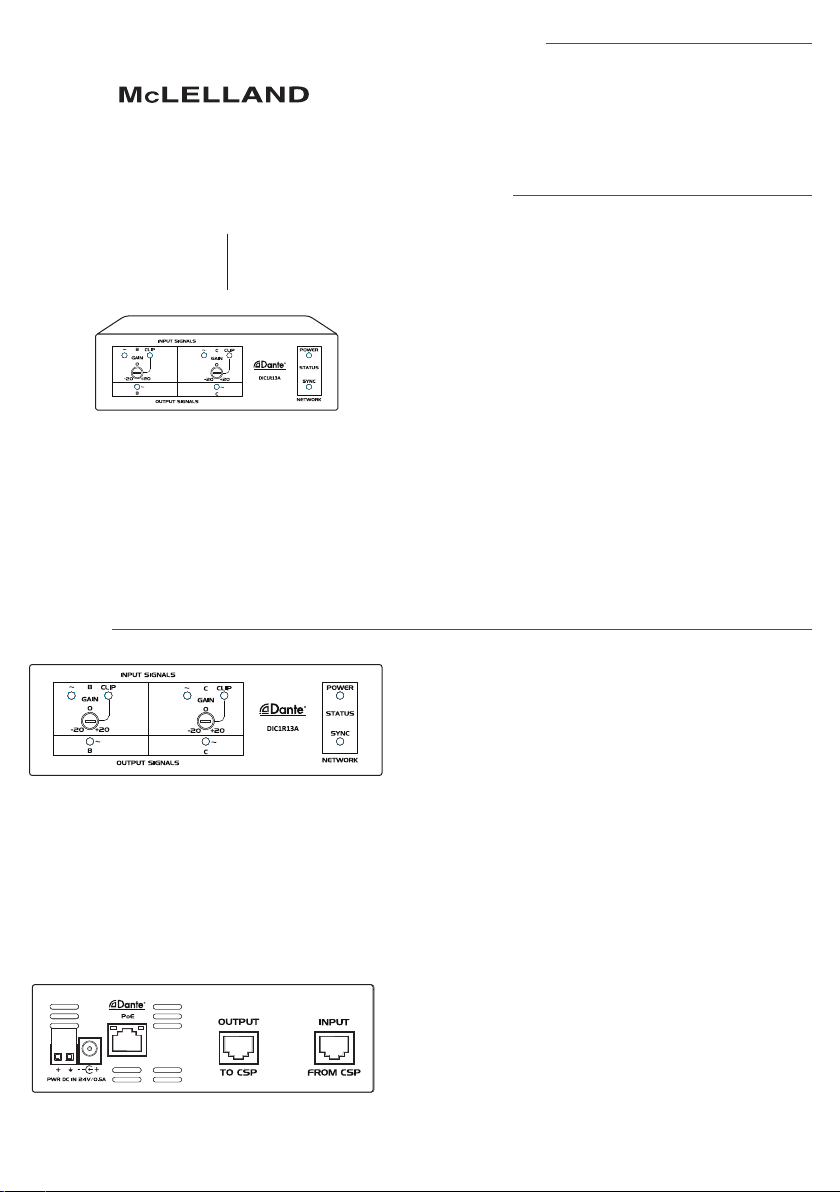
1.Gain Control: Adjust the level of input signal on each input
channel.
Note: Input B, C corresponds to Pair B and C of Connected
CSP product.
2.Input signal level LED on each channel.
3.Signal CLIP LED on each input channel.
4.Output signal level LED on each output channel.
5.Power LED indicator.
6.SYNC LED indicates the status of Dante network.
7.RJ45 Input Jack: Two input channel, accepts the signal from
Pair B, C of CSP
product.
8.RJ45 Output Jacks: Two output channels to Pair B and Pair
C of CSP receivers or
distributor.
9.RJ45 Dante port: Using Cat5 cable to connect to Dante
network.
Note: When using PoE enabled network switch, DIC1R13A
could be powered and operation from PoE.
10.Power: Connect DC 24V to 2P terminal block or DC input
jack.
Note: 1. When DC 24V and PoE are both present to DIC1R13A,
the unit will operate from DC 24V. And when DC 24V
removed, the power will switch over to PoE power
automatically.
2. When DIC1R13A powered from 24VDC power supply,
the power will present at RJ45 input jack and RJ45 output
jack. Provides the power to all the CSP products connect to
RJ45 input / output jack.
3. When DIC1R13A powered from PoE, it will only power
up DIC1R13A for
normal operation. All the CSP products connected to
RJ45 input / output jack need to have separate power supply.


