ESD electronic CPCI-ETH2 User manual

CPCI-ETH2
10/100/1000BASE-T
Interface for CompactPCI®
Hardware Manual
to Product I.2321.02
CPCI-ETH2 Hardware Manual • Doc. No.: I.2321.21 / Re . 1.1 Page 1 of 15
esd electronic system design gmbh
Vahrenwalder Str. 207 • 30165 Hannover • ermany
http://www.esd.eu
Phone: +49 (0) 511 3 72 98-0 • Fax: +49 (0) 511 3 72 98-68

N O T E
The information in this document has been carefully checked and is belie ed to be entirely reliable.
esd makes no warranty of any kind with regard to the material in this document, and assumes no
responsibility for any errors that may appear in this document. In particular descriptions and
technical data specified in this document may not be constituted to be guaranteed product features
in any legal sense.
esd reser es the right to make changes without notice to this, or any of its products, to impro e
reliability, performance or design.
All rights to this documentation are reser ed by esd. Distribution to third parties, and reproduction
of this document in any form, whole or in part, are subject to esd's written appro al.
© 2015 esd electronic system design gmbh, Hanno er
esd electronic system design gmbh
Vahrenwalder Str. 207
30165 Hanno er
Germany
Phone: +49-511-372 98-0
Fax: +49-511-372 98-68
E-Mail: [email protected]
Internet: www.esd.eu
Trademark Notices
CompactPCI® is a registered trademark of the PCI Industrial Computers Manufacturers Group.
All other trademarks, product names, company names or company logos used in this manual are reser ed by their
respecti e owners.
Page 2 of 15 Hardware Manual • Doc. No.: I.2321.21 / Re . 1.1 CPCI-ETH2

ocument file: I:\Texte\Doku\MANUALS\CPCI\Eth2\English\CPCI-ETH2-Hardware_Manual_en_11.odt
ate of print: 2015-09-28
ocument type
number: DOC0800
Hardware version: CPCIET Re . 1.0
ocument History
The changes in the document listed below affect changes in the hardware as well as changes in
the description of the facts, only.
Rev. Chapter Changes versus previous version ate
1.0 - First Englisch ersion 2005-07-05
1.1
-The CPCI-ETH2-FX and CPCI-ETH2-MX ersions are deleted,
manual restructured, Safety Instructions inserted
2015-09-28
1. Block circuit diagram new, “Front Panel View” with LEDs and Connectors”
2. Chapter “Hardware Installation” re ised
3. Chapter “Technical Data”, description of Fibre Optic Interface deleted
4. Note inserted
5. EU-Declaration of Conformity inserted
6. Chapter “Order Information” mo ed and re ised
Technical details are subject to change without further notice.
CPCI-ETH2 Hardware Manual • Doc. No.: I.2321.21 / Re . 1.1 Page 3 of 15

Safety Instructions
● When working with the CPCI-ETH2 follow the instructions below and read the manual carefully to protect yourself from
injury and the CPCI-ETH2 from damage.
● The de ice is a built-in component. It is essential to ensure that the de ice is mounted in a way that cannot lead to
endangering or injury of persons or damage to objects.
● The de ice has to be securely installed in the control cabinet before commissioning.
● Protect the CPCI-ETH2 from dust, moisture and steam.
● Protect the CPCI-ETH2 from shocks and ibrations.
● The CPCI-ETH2 may become warm during normal use. Always allow adequate entilation around the CPCI-ETH2 and
use care when handling.
● Do not operate the CPCI-ETH2 adjacent to heat sources and do not expose it to unnecessary thermal radiation.
Ensure an ambient temperature as specified in the technical data.
● Do not use damaged or defecti e cables to connect the CPCI-ETH2 and follow the CAN wiring hints in chapter:
"Correctly Wiring Electrically Isolated CAN Networks".
● In case of damages to the de ice, which might affect safety, appropriate and immediate measures must be taken, that
exclude an endangerment of persons and domestic animals and property.
● Current circuits which are connected to the de ice ha e to be sufficiently protected against hazardous oltage (SELV
according to EN 60950-1).
● The CPCI-ETH2 may only be dri en by power supply current circuits, that are contact protected.
A power supply, that pro ides a safety extra-low oltage (SELV or PELV) according to EN 60950-1, complies with this
conditions.
ANGER
Hazardous Voltage - Risk of electric shock due to unintentional contact with uninsulated li e parts with high
oltages inside of the system into which the CPCI-ETH2 is to be integrated.
► Disconnect all hazardous oltages (mains oltage) before opening the system.
NOTICE
Electrostatic discharges may cause damage to electronic components.
To a oid this, please perform the steps described on page 10 before you touch the CPCI-ETH2, in order to
discharge the static electricity from your body.
Qualified Personal
This documentation is directed exclusi ely towards personal qualified in control and automation engineering.
The installation and commissioning of the product may only be carried out by qualified personal, which is authorized to
put de ices, systems and electric circuits into operation according to the applicable national standards of safety
engineering.
Conformity
The CPCI-ETH2 is an industrial product and meets the demands of the EU regulations and EMC standards printed in the
conformity declaration at the end of this manual.
Warning: In a residential, commercial or light industrial en ironment the CPCI-ETH2 may cause radio interferences in
which case the user may be required to take adequate measures.
ata Safety
This de ice is equipped with an Ethernet or other interface which is suitable to establish a connection to data networks.
Depending on the software used on the de ice, these interfaces may allow attackers to compromise normal function, get
illegal access or cause damage.
esd does not take responsibility for any damage caused by the de ice if operated at any networks. It is the responsibility
of the de ice's user to take care that necessary safety precautions for the de ice's network interface are in place.
Intended Use
The intended use of the CPCI-ETH2 is the operation as Ethernet interface in a CompactPCI system.
The guarantee gi en by esd does not co er damages which result from improper use, usage not in accordance with
regulations or disregard of safety instructions and warnings.
● The CPCI-ETH2 is intended for installation in a CompactPCI system only.
● The operation of the CPCI-ETH2 in hazardous areas, or areas exposed to potentially explosi e materials is not
permitted.
● The operation of the CPCI-ETH2 for medical purposes is prohibited.
Service Note
The CPCI-ETH2 does not contain any parts that require maintenance by the user. The CPCI-ETH2 does not require any
manual configuration of the hardware.
isposal
De ices which ha e become defecti e in the long run ha e to be disposed in an appropriate way or ha e to be returned
to the manufacturer for proper disposal. Please, make a contribution to en ironmental protection.
Page 4 of 15 Hardware Manual • Doc. No.: I.2321.21 / Re . 1.1 CPCI-ETH2

Table of contents
1. O er iew...................................................................................................................................... 8
1.1 Description of the CPCI-ETH2...............................................................................................8
1.2 Front Panel View with LEDs and Connectors.........................................................................9
1.3 LED Indication.......................................................................................................................9
2. Hardware Installation.................................................................................................................. 10
3. Technical Data............................................................................................................................11
3.1 General Technical Data........................................................................................................11
3.2 CompactPCI Bus..................................................................................................................11
3.3 Ethernet Interface................................................................................................................12
3.4 Software Support ................................................................................................................12
4. Connector Assignments.............................................................................................................. 13
4.1 Ethernet............................................................................................................................... 13
5. EU Declaration of Conformity.....................................................................................................14
6. Order Information....................................................................................................................... 15
CPCI-ETH2 Hardware Manual • Doc. No.: I.2321.21 / Re . 1.1 Page 5 of 15

Typographical Conventions
Throughout this design specification the following typographical con entions are used to
distinguish technical terms.
Convention Example
File and path names /dev/null or <stdio.h>
Function names open()
Programming constants NULL
Programming data types uint32_t
Variable names Count
The following indicators are used to highlight noticeable descriptions.
Attention:
Warnings or cautions to tell you about operations which might ha e unwanted side
effects.
Note:
Notes to point out something important or useful.
Number Representation
All numbers in this document are base 10 unless designated otherwise. Hexadecimal numbers
ha e a prefix of 0x, and binary numbers ha e a prefix of 0b. For example, 42 is represented as
0x2A in hexadecimal and 0b101010 in binary.
Abbreviations
API Application Programming Interface
CAN Controller Area Network
CPU Central Processing Unit
CiA CAN in Automation
HW Hardware
I/O Input/Output
LSB Least Significant Bit
MSB Most Significant Bit
n.a. not applicable
OS Operating System
SDK Software De elopment Kit
CPCI-ETH2 Hardware Manual • Doc. No.: I.2321.21 / Re . 1.1 Page 7 of 15

Overview
1. Overview
1.1 escription of the CPCI-ETH2
Figure 1: Block circuit diagram
The CPCI-ETH2 is a CompactPCI board in Euro format.
The Intel 82546GB Gigabit controller pro ides two Gigabit ports on a single compact component.
Both Gigabit Ethernet ports are equipped as two 10/100/1000BASE-T Ethernet interfaces.
The CPCI-ETH2-module operates with standard Ethernet dri ers.
The Ethernet interfaces for 10/100/1000BASE-T-networks are easily accessible ia RJ45-sockets
in the front panel. The interfaces are electrically isolated from the Ethernet controller.
LEDs in the front panel indicate the status of the CPCI-ETH2.
Page 8 of 15 Hardware Manual • Doc. No.: I.2321.21 / Re . 1.1 CPCI-ETH2
Electrical Isolation
IRQ
Ethernet Twisted Pair
10/100/1000BaseT
RJ45-Buchse
4 LEDs er Channel
Com actPCI Connector
Electrical Isolation
Flash
EPROM
Intel 82546GB
Dual Port
Gigabit Ethernet
Controller

Overview
1.2 Front Panel View with LE s and Connectors
Figure 2: Connectors and LEDs
1.3 LE Indication
Interface LE Name Colour Indication of the LE (LE on)
LED name
in schematic
diagram
GB-
Ethernet 2
LEthernet
Link 2 green Link Status-Ethernet 2 (10/100/1000BaseT)
(Link to ser er or hub detected) LED400A
AActi ity green Acti ity, access of Ethernet 2 to the Dual Gigabit
Ethernet controller 82546GB LED400B
C100 Mbit/s
Ethernet green Speed 100 (C) Status Ethernet 2, interface operates
with a bit rate of 100 Mbit/s. (at 10/1000 Mbit/s LED off). LED400C
M1000 Mbit/s
Ethernet green Speed 1000 (M) Status Ethernet 2, interface operates
with a bit rate of 1000 Mbit/s. (at 10/100 Mbit/s LED off). LED400D
GB-
Ethernet 1
LEthernet
Link 1 green Link Status-Ethernet 1 (10/100/1000BaseT)
(Link to ser er or hub detected) LED300A
AActi ity green Acti ity, access of Ethernet 1 to the Dual Gigabit
Ethernet controller 82546GB LED300B
C100 Mbit/s
Ethernet green Speed 100 (C) Status Ethernet 1, interface operates
with a bit rate of 100 Mbit/s. (at 10/1000 Mbit/s LED off). LED400C
M1000 Mbit/s
Ethernet green Speed 1000 (M) Status Ethernet 1, interface operates
with a bit rate of 1000 Mbit/s. (at 10/100 Mbit/s LED off). LED300D
Table 1: Description of LEDs
CPCI-ETH2 Hardware Manual • Doc. No.: I.2321.21 / Re . 1.1 Page 9 of 15

Hardware Installation
2. Hardware Installation
Read the safety instructions at the beginning of this document carefully, before
you start with the hardware installation!
ANGER
Hazardous Voltage - Risk of electric shock due to unintentional contact with
uninsulated li e parts with high oltages inside of the system into which the CPCI-
ETH2 is to be integrated.
► Disconnect all hazardous oltages (mains oltage) before opening the system.
NOTICE
Electrostatic discharges may cause damage to electronic components. To a oid this,
please discharge the static electricity from your body by touching the metal case of the
CompactPCI system before you touch the CPCI-ETH2.
Furthermore, you should pre ent your clothes from touching the CPCI-ETH2, because
your clothes might be electrostatically charged as well.
Procedure:
1. Switch off your CompactPCI system and all connected peripheral de ices (monitor, printer,
etc.).
2. Discharge your body as described abo e.
3. Disconnect the CompactPCI system from the mains.
ANGER
Hazardous Voltage - Risk of electric shock due to unintentional contact with
uninsulated li e parts with high oltages inside of the system into which the
CPCI-ETH2 is to be integrated.
► Disconnect all hazardous oltages (mains oltage) before opening the
system.
If the system does not ha e a flexible mains cable, but is directly connected to
mains, disconnect the power supply ia the safety fuse and make sure that the
fuse cannot switch on again unintentionally (e.g. with caution label).
4. Insert the CPCI-ETH2 board into a free CompactPCI slot. Carefully push the board until it
snaps into place.
5. Fix the CPCI-ETH2 module with the mounting screws in the front panel.
7. Connect the Ethernet cables (10/100/1000BASE-T) to the RJ45-sockets in the front panel of
the CPCI-ETH2.
8. Connect the CompactPCI system to mains again (mains connector or safety fuse).
9. Switch on the CompactPCI system and the peripheral de ices.
10. End of hardware installation.
11. Now you can install the Gigabit Ethernet interface. Refer to the documentation of your
operating system.
Page 10 of 15 Hardware Manual • Doc. No.: I.2321.21 / Re . 1.1 CPCI-ETH2

Technical ata
3. Technical ata
3.1 General Technical ata
Power supply
oltage
ia CompactPCI bus,
nominal oltages: 5 V ± 5% and 3.3 V ± 5%
current consumption: max. 0.75 A at 3.3V
Connectors
X100 (132-pin post connector) -
CompactPCI-board connector P1
X101 (132-pin post connector) -
CompactPCI-board connector P2
X320 (8-pin RJ45-socket) - Ethernet Twisted Pair,
10/100/100BASE-T
X420 (8-pin RJ45-socket) - Ethernet Twisted Pair,
10/100/1000BASE-T
Temperature
range 0...50 °C ambient temperature
Humidity max. 90%, non-condensing
Dimensions 100 mm x 160 mm
(without connectors)
Weight 165 g
Table 2: General data of the module
3.2 CompactPCI Bus
Host bus PCI-Bus according to PCI Local Bus Specification 2.3
PCI-data/ address bus 64 Bit
Controller Intel 82546GB
Interrupt Interrupt signal A, B
Board dimensions according to CompactPCI-Specification, Re . 1.0
Connectors
Connector coding Uni ersal-Board (3.3 V or 5 V signalling oltage)
not keyed
Table 3: Data of the CompactPCI Bus
CPCI-ETH2 Hardware Manual • Doc. No.: I.2321.21 / Re . 1.1 Page 11 of 15

Technical ata
3.3 Ethernet Interface
Number of Ethernet
interfaces 2
Bit rate 10Mbit/s, 100 Mbit/s, 1000 Mbit/s
Connection Twisted Pair (compatible to IEEE 802.3),
10BASE-T, 100BASE-TX, 1000BASE-T
Electrical isolation ia transformer integrated in the connector
Connector RJ-45-sockets in the front panel
Table 4: Data of the Ethernet interface
3.4 Software Support
The CPCI-ETH2-module operates with standard system dri ers of Windows NT/2000, Linux,
VxWorks and QNX.
Page 12 of 15 Hardware Manual • Doc. No.: I.2321.21 / Re . 1.1 CPCI-ETH2
Connector Assignments
4. Connector Assignments
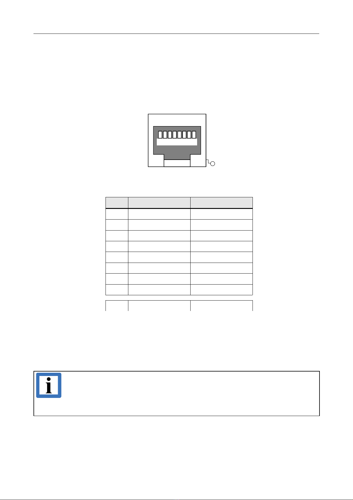
4.1 Ethernet
evice connector: RJ45 socket, 8-pin
Pin Position:
Pin Assignment:
Pin Signal Meaning
1 MDI0+ (TxD+) Transmit Data +
2 MDI0- (TxD-) Transmit Data -
3 MDI1+ (RxD+) Recei e Data +
4 MDI2+ -
5 MDI2- -
6 MDI1- (RxD-) Recei e Data -
7MDI3+ -
8 MDI3- -
S Shield
Signal escription:
MDIx+/- ... Ethernet data lines
- ... reser ed for future applications, do not connect!
Shield... case shield, connected with the front panel of the CPCI-ETH2.
Note:
Cables of category CAT-5e SF/UTP or higher ha e to be used to grant the function in
networks with 1000 Mbit/s.
esd grants the EC conformity of the product, if the wiring is carried out with shielded
twisted pair cables.
CPCI-ETH2 Hardware Manual • Doc. No.: I.2321.21 / Re . 1.1 Page 13 of 15
1 2 3 4 5 6 7 8
S

EU eclaration of Conformity
5. EU eclaration of Conformity
Page 14 of 15 Hardware Manual • Doc. No.: I.2321.21 / Re . 1.1 CPCI-ETH2

Order Information
6. Order Information
Type Properties Order No.
CPCI-ETH2
Dual 10/100/1000BASE-T Ethernet
CompactPCI 3U/4HP card
with 2 Ethernet interfaces
I.2321.02
For detailed information about the dri er a ailability of your special operating system, please contact our sales team.
Table 5: Order information
P F Manuals
Manuals are a ailable in English, see table below.
Please download the manuals as PDF documents from our esd website www.esd.eu for free.
Manuals Order No.
CPCI-ETH2-ME Hardware manual in English I.2321.21
Table 6: A ailable manuals
Printed Manuals
If you need a printout of the manual additionally, please contact our sales team: [email protected] for
a quotation. Printed manuals may be ordered for a fee.
CPCI-ETH2 Hardware Manual • Doc. No.: I.2321.21 / Re . 1.1 Page 15 of 15
This manual suits for next models
1
Table of contents
Other ESD electronic Recording Equipment manuals


