COMPASS HIGH BAY • 100-277V
INSTALL INSTRUCTIONS
Specifications are subject to change without notice. Photos and line
drawings may not be to scale and are for general reference only.
© 2018 MEBULBS division of Premium Quality Lighting 3001 S University Dr • Fargo ND, 58104 • 1800-MEBULBS
MEBULBS • WWW.MEBULBS.COM
PLEASE FIND A QUALIFIED ELECTRICIAN FOR INSTALLATION. Please read
the instructions before you install and use the luminaire.
WARNING, CAUTIONS AND OPERATING INSTRUCTIONS
• To reduce the risk of death, personal injury or property damage from
fire, electric shock, falling parts, cuts/abrasions, and other hazards read
all warnings and instructions included with and on the fixture box and all
fixture labels.
• Before installing, servicing, or performing routine maintenance upon this
equipment, follow these general precautions.
• Commercial installation, service and maintenance of luminaires should be
performed by a qualified licensed electrician.
• For The installation: If you are unsure about the installation or maintenance
of the luminaires, consult a qualified licensed electrician and check your
local electrical code.
• To prevent wiring damage or abrasion, do not expose wiring to edges of
sheet metal or other sharp objects.
• Do not make or alter any open holes in an enclosure of wiring or electrical
components during kit installation.
WARNING: RISK OF FIRE OR ELECTRICAL SHOCK
• Turn o electrical power at fuse or circuit breaker box before wiring fixture
to the power supply.
• Turn o the power when you perform any maintenance.
• Verify that supply voltage is correct by comparing it with the luminaire
label information.
• Make all electrical and grounded connections in accordance with the
National Electrical Code and any applicable local code requirements.
• All wiring connections should be capped with UL approved wire
connectors.
CAUTION: RISK OF INJURY
• Avoid direct eye exposure to the light source while it is on.
• Account for small parts and destroy packing material, as these may be
hazardous to children.
• Mounting surface should be of suicient strength to hold more than the
weight of the fixture.
• Suitable for Wet locations.
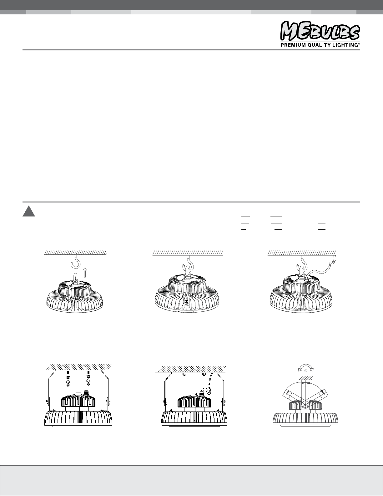
!WARNING DISCONNECT POWER BEFORE INSTALLING OR SERVICING.
1. Drill a hole into the ceiling for the
appropriate size hook. (hook provided by
installer)
HOOK INSTALLATION • 100W / 150W / 200W / 240W
BRACKET INSTALLATION • 100W / 150W / 200W / 240W *bracket not included
LN
G
LN
G
1. Attach the bracket to the mounting
surface.
2. Secure hook to the ceiling and hang the
fixture from the hook.
3. Connect the electrical cables; Brown-L,
Blue-N, Yellow/Green-Ground. If using in wet
locations, ensure all electrical connections
and installation holes have a water tight seal.
3. Adjust the bracket to the beam angle you
need.
2. Connect the electrical cables; Brown-L,
Blue-N, Yellow/Green-Ground. If using in wet
locations, ensure all electrical connections
and installation holes have a water tight seal.
120° adjustable
beam angle
GENERAL WIRING DIAGRAM
Brown (Line)
TO LINE VOLTAGE
100-277V
1-10V dimmableWhite (DIM-)Yellow/Green (Grd)
Blue (Neutral) Blue (DIM+) 1-10V dimmable
*CAP DIMMING WIRES SEPARATELY IF NOT USING THE DIMMING FUNCTION.
TO DIMMER 1-10V


