Mectronic Opton BiPower Y2 User manual

User Manual
Opton BiPower Y2 Model
© Mectronic Medicale - UM.OPF-Y2_EN_2021-04_001
2
Pictures
G
L
H
I
M
N
P
O
F
A
C
D
E
B
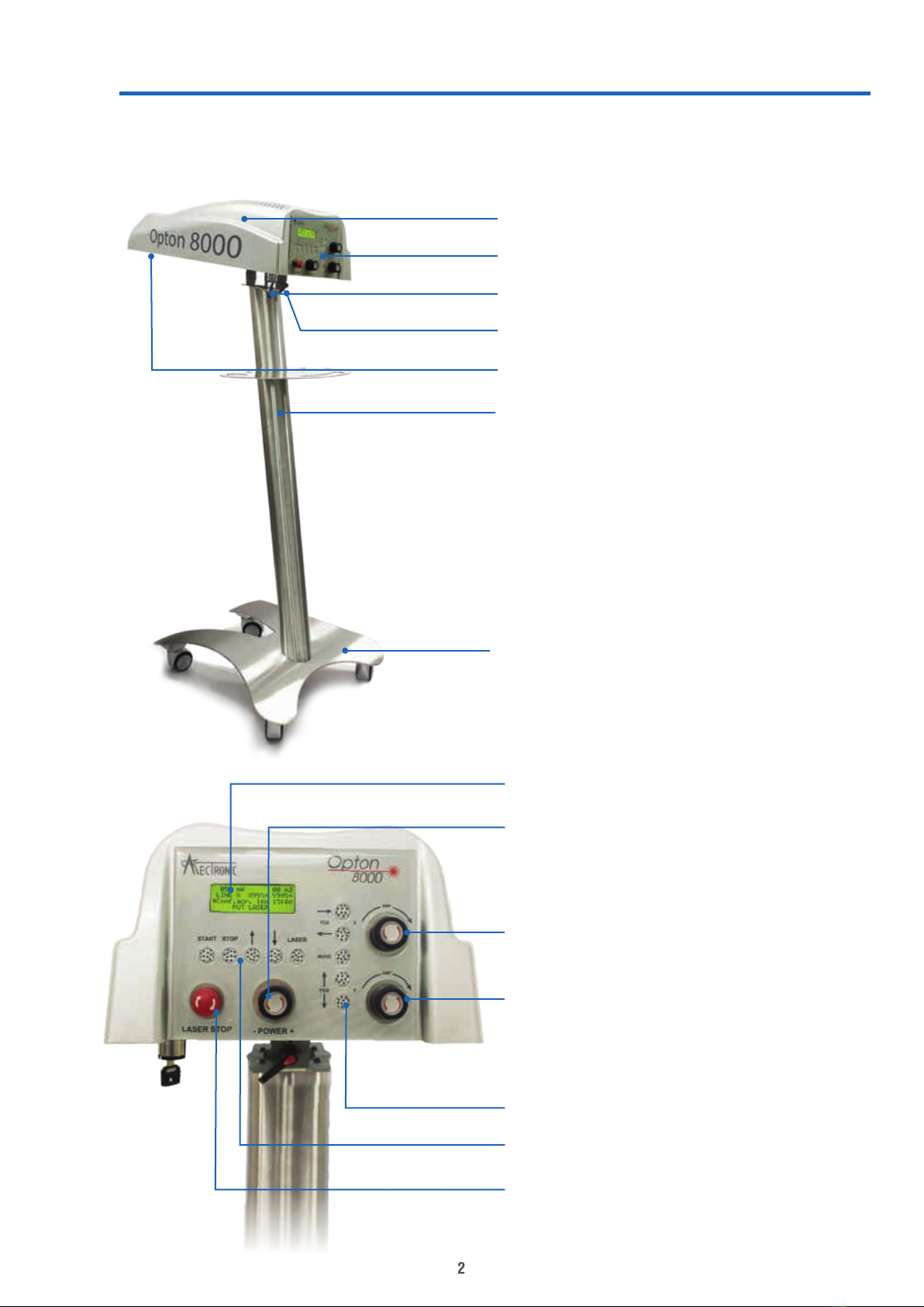
A. Laser unit
B. Control panel
C. Main switch (key)
D. Lateral movement locking lever
E. Laser emission point
F. Stand
G. Trolley base
H. Screen
I. Laser power regulation
L. X axis area adjustment
M. Y axis area adjustment
N. Verical keys: scan control
O. Horizontal keys: start & stop
commands, display interraction
P. Emergency stop button
3
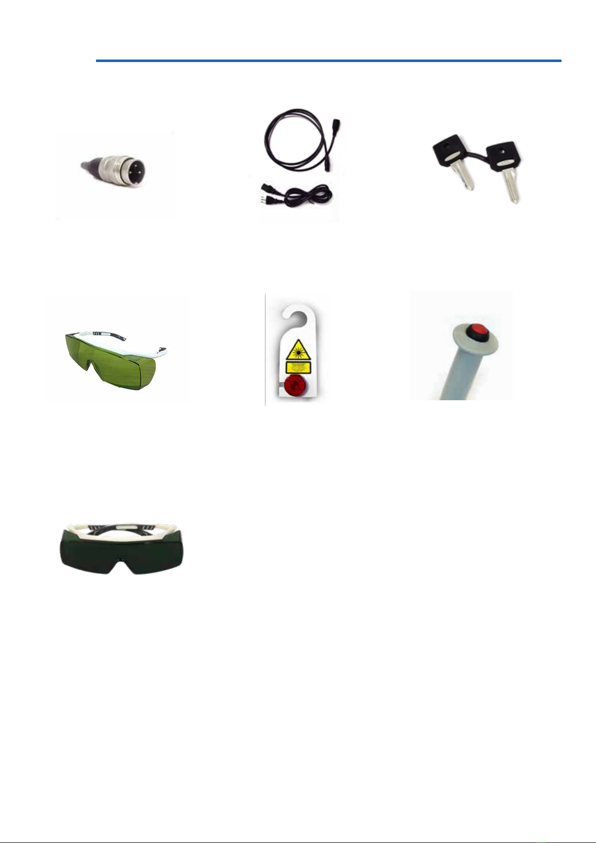
Accessories
Protective glasses
COD. 651
Laser warning sign
COD. LAMP
Patient button (only CO2
models)
COD. 80054
2 x 3 pole interlocks
(1 x 3 pole interlock on CO2
models)
COD. 80038
Start keys
COD. 455
Power cable
COD. 80035
Protective glasses only with
650nm
COD. 80004XP

4
Index
1. Introduction........................................................................ 6
1.1 What is the Opton BiPower Y2? ................................. 6
1.2 What is the Opton BiPower Y2 for?............................ 6
1.3 Advantages................................................................. 6
1.4 Who can use the Opton BiPower Y2?......................... 6
1.5 Indications.................................................................. 7
1.6 Contraindications........................................................ 8
2. Quick use guide ................................................................. 9
3. Instructions ...................................................................... 12
3.1 Interface ................................................................... 12
3.1.1 Display............................................................ 12
3.1.2 Keyboard......................................................... 13
3.1.3 Power Knob .................................................... 14
3.1.4 Size Knob........................................................ 14
3.1.4 Emergency stop button................................... 14
3.2 Method of use .......................................................... 15
3.2.1 Timer setting.................................................. 15
3.2.2 Mode setting................................................... 15
3.2.3 Pathologies ..................................................... 16
3.2.4 Calibration....................................................... 16
3.2.5 Signals and Alarms ......................................... 16
4. Warning ........................................................................... 17
4.1 Attention during use ................................................. 17
5. Norms and safety............................................................. 18
5.1 Laser norms ............................................................. 18
5.2 Safety ....................................................................... 18

5
5.3 Patient safety............................................................ 20
5.4 Classication ............................................................ 21
5.5 DNRO ....................................................................... 22
6. Maintenance .................................................................... 23
6.1 Ordinary maintenance............................................... 23
6.2 Troubleshooting and periodical maintenance ........... 23
7. Labels .............................................................................. 24
7.1 Generic Labeling....................................................... 24
7.2 Specic Labeling ...................................................... 25
8. Technical data ................................................................. 26
9. EMC Tables...................................................................... 27

6
1. Introduction
1.1 What is the Opton
BiPower Y2?
The Opton BiPower Y2 is a scanning laser system designed for the treatment
of muscular-skeletral pathologies. Mectronic Medicale’s scanning system
allows the area to be treated to be dened, allowing a balanced distribution
of laser energy in the zone in question, reducing the margin of error.
1.2 What is the Opton
BiPower Y2 for?
1.3 Advantages
The Opton BiPower Y2 is able to generate continuous laser emission,
causing bio-stimulation deep within tissues and reactivating cellular
metabolism. The continuous emission allows the deepest tissues to be
reached, resolving the problem at its source.
Innumerable congurations of power and wavelengths.
The laser beam can be aimed and adjusted in area, so large areas of the
body can be treated. This can also be accomplished thanks to the lateral
movement of the Opton BiPower Y2.
Treatment independent of the manual activity of the therapist.
Pathology library with pre-set treatment protocols.
Emergency stop system.
1.4 Who can use the
Opton BiPower Y2?
The Opton BiPower Y2 has the same use as a laser therapy system.
Laser therapy is used in the eld of physical therapy and pain relief.
Operators are qualied, competent personnel from the following categories:
Medical staff:
Physios
Sports doctors
Orthopaedists
Anaesthetists
Doctors
Paramedic staff:
Rehabilitation therapists
Physiotherapists
Masso-therapists
Radiology technicians

7
Subacromial conict
Rotator cuff injury
Arthrosis
Calcication
Epicondylitis
Epitrocleitis
Bunions
Aftereffects of Fractures
Tendinitis
Carpal Tunnel Syndrome
Rizarthritis
Snap nger
Dupuytren’s disease
Popliteal cyst
Spe syndrome
Distortion of the Patella
Patellar tendonitis
Pubalgia
Gonarthrosis
Treatment following anterior cruciate ligament reconstruction surgery
Goose leg bursitis
Sprains
Plantar fasciitis
Achilles tendonitis
Flick
Back pain
Cervical pain
Cervicobrachialgia
Contractures
Spondylodiscoarthrosis
Low back pain
Sciatica
Coxarthrosis
Piriformis Syndrome
Sciatica
Radiculopathies
Neuropathies
Muscular Injuries
Anti-edema action
Tendinopathies
Pain therapy
Induratio Penis Plastica
Arthritis
Rheumatism
Pelvic Floor Treatment
Lymphatic Drainage
TMJ syndrome
Tendinitis
Shoulder Osteoarthritis
1.5 Indications

8
As the laser source is in the near infra-red, there are two types of
contraindication:
- Eye damage
- Heat damage to tissue exposed to treatment, with particular attention to
continuous emission and the phototype of the patient.
The rst is avoided by the use of protective glasses, while the second can
be negated by the skill of the operator, who must evaluate the correct
thermal sensitivity of the patient and the phototype. Use the values and
usage details given in the pathology section.
In particular, avoid use on:
- Patients with suspected or obvious neoplasm
- Pregnant women
- Treatment of photo-sensitive areas
- Treatment of infected areas
- Epileptic patients
- Areas of haemorrhage
- Treatment of the sympathetic nerve, vagus nerve, or cardiac area of
patients with cardiac problems.
1.6 Contraindications

9
2. Quick use guide
Before using the Opton BiPower Y2, ensure it is securely positioned.
Make sure the main key switch is in the OFF position (turned to the left).
Make sure that the power cable is connected to the machine, and is plugged in.
After connecting the supplied
interlock to the machine, the Opton
BiPower Y2 is fully functional,
the door switch connection must
be carried out by a qualied
electrician.
(pag. 17).
*For models 8000 C, Bi-Power
980, Bi-Power 810 and Bi-Power
1064.
Connect the patient button to the
appropriate connector under the
body of the laser, labelled ‘Patient
Safety’.
The patient button is a further
safety measure for use during
treatment: the patient can interrupt
the treatment at any time.
The power socket is positioned
under the main body of the laser;
connect the power cable to a
power socket.
Connect the interlock in the
suitable socket under the laser
body.
10
Check the screen turns on. After
the appearance of the ‘Opton
BiPower Y2’ logo and the software
version, press ‘Laser’ on the
horizontal keyboard and select the
suitable parameters (Power, Time,
Area, Scan mode. See page 13).
This command activates the guide
light.
LASER STOP
START LASER
MODE
POS
POS Y
X
AMP
STOP
AMP
Turn the main key switch, under
the laser, from left to right.
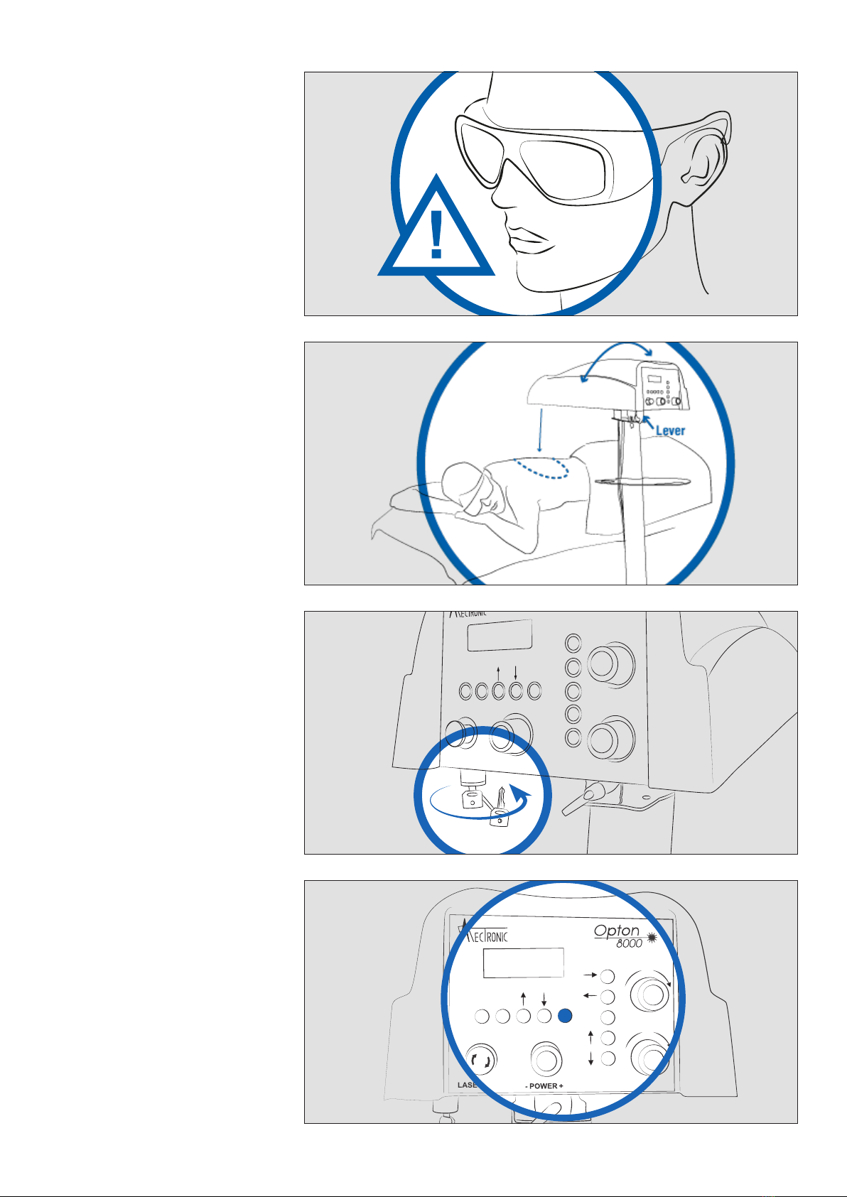
Position the Opton BiPower Y2
so that it covers the area to be
treated.
Use the locking lever to adjust
the position if oblique emission is
required.
Make sure that all persons present
wear certied protective glasses.

11
*For models 8000 C, Bi-Power
980, Bi-Power 810 and Bi-Power
1064.
The stop button must be available
for use by the patient throughout
the treatment.
At the end of the treatment,
switch off the machine using the
key switch.
Remove the key when the
machine is not in use, so as to
avoid unauthorised use.
After setting the required values,
start the treatment by pressing the
START button.
This command starts the powered
laser.
LASER STOP
START LASER
MODE
POS
POS Y
X
AMP
STOP
AMP

12
3. Instructions
A
B
E
A
B
C
D
F
D
C
gure 1
gure 2
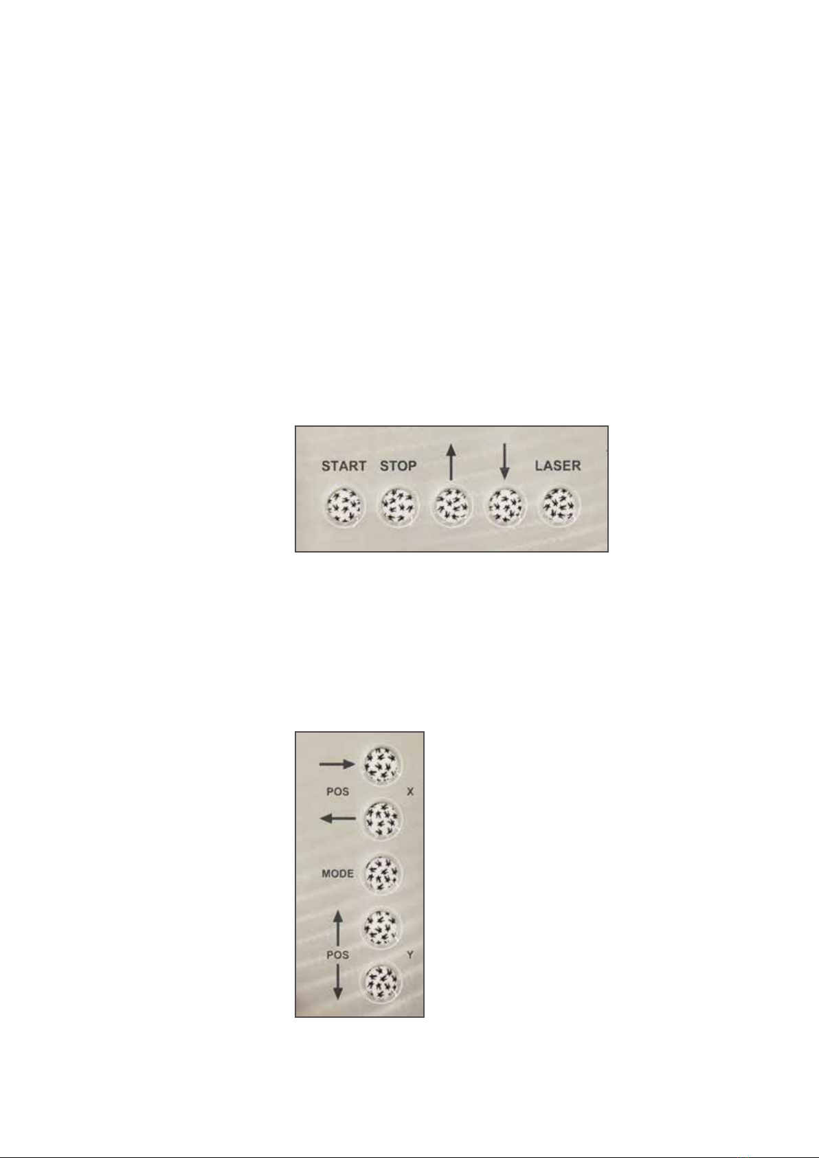
The control panel features the following:
A) Display: operative parameters and meaasges are displayed
B) Horizontal keyboard: start-stop commands and display interaction
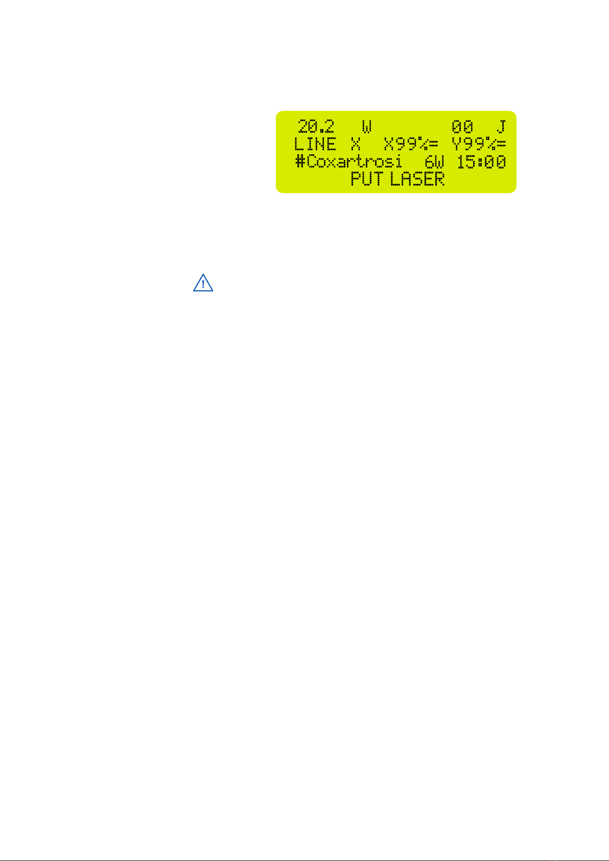
C) Emergency stop button
D) Vertical keyboard: scan control
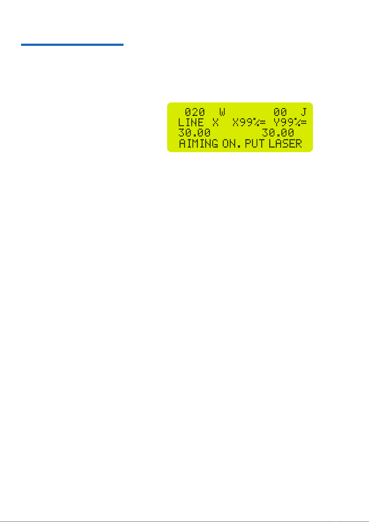
E) Size knob: amplitude adjustment on x and y axes
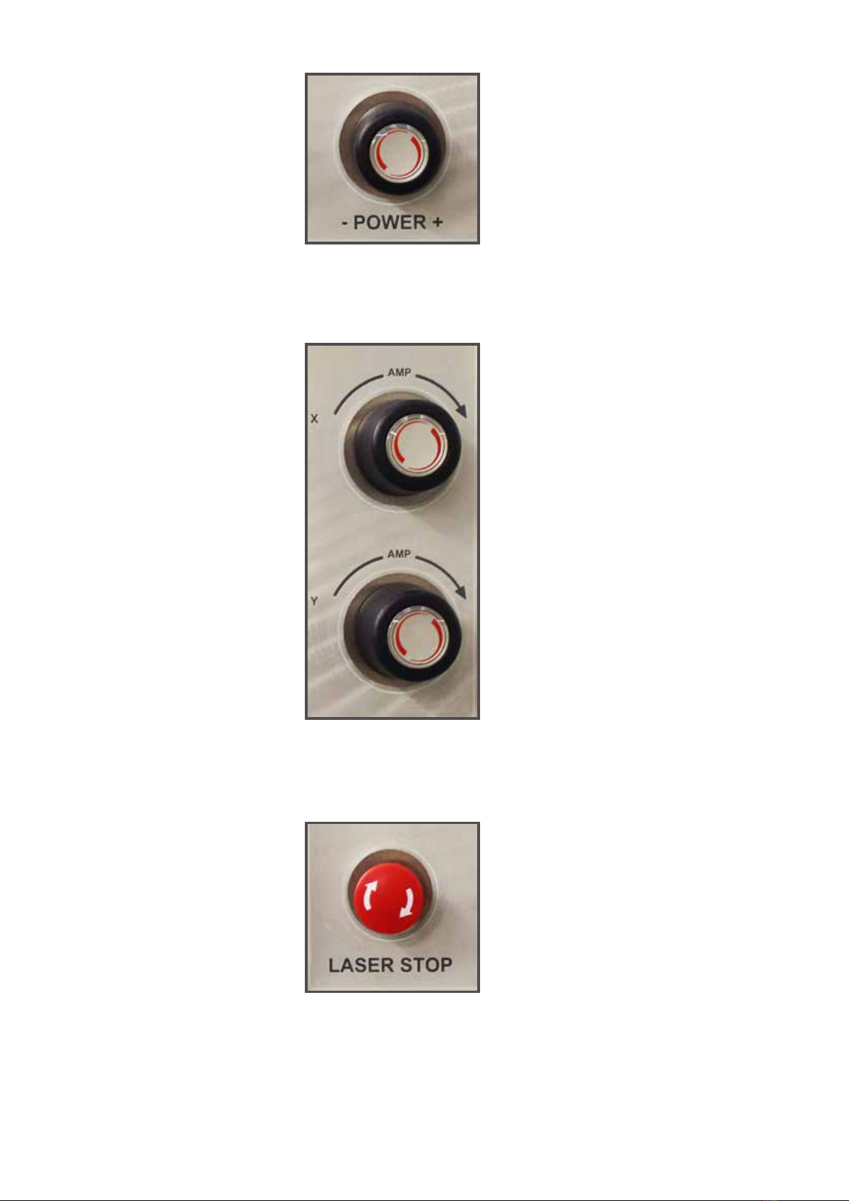
F) Power knob: laser power adjustment
A) Emitted laser power (W)
Energy emitted (J)
B) Selected mode:
- Line X
- Line Y
- Circle
Percentage size adjustment X and Y
C) Treatment time set
Remaining treatment time
The display gives information on power, time, and set parameters.
3.1 Interface
3.1.1 Display
13
D) Display messages:
- PUT LASER: press Laser button
- AIMING ON, PUT START: Laser on, press Start button
- POWER LASER ON: Power laser on
- LASER CALIBRATION: calibration control
- CALIBRATION OK
- CALIBRATION FAULT
- INTERLOCK OPEN
- SCANNING FAILURE
- SMALL AREA! DANGER!: Scanning area too small
- START: turns the power laser on
- STOP: turns the power laser and the guide laser off and resets the timer
- Arrows: modify scan mode and adjust timer
- LASER: turn on the laser guide
- POS X: the arrows move the scan area left or
right
- POS Y: the arrows move the scan area up or
down
- MODE: switch display between modify time
parameters, scan type, and pathology library.
Using the arrows on the keyboard it is possible to
change these parameters.
The horizontal keyboard allows the laser functions to be set:
gure 3
gure 4
3.1.2 Keyboard
14
The knob is used to adjust the laser power
according to the label data
The two knobs separately adjust the area
of the scan area on two axes, X and Y. The
display shows the percentage of the pre-
selected area.
With CO2lasers, if the area is too small in
relation to the power selected, an error
message is displayed (Small Area! Danger!).
To fix this fault:
- Increase the area
- Decrease the power
The emergency stop button is positioned on
the left of the control panel. This stops laser
emission immediately.
To restart laser emission, repeat the
command on the control keyboard.
3.1.3 Power Knob
3.1.4 Size Knob
3.1.4 Emergency stop button
gure 7
gure 5
gure 6
15
3.2 Method of use By pressing the Laser button the guide light is activated.
The display shows the message “AIMING ON, PUT LASER”. (g.8)
At this time the laser is not working, just allowing positioning of the laser
in the area in question to be treated, and the area to be changed.
To change the area of the laser use the Size Knob.
The changed value are shown on the display in the second line
(X 99% - Y 99%).
To change the position of the laser use the arrows on the vertical keyboard
POS x and POS y.
To modify the power use the Power Knob: the level is shown in the rst
row (000 W).
By pressing the MODE button it is possible to modify the therapy time and
the emission mode (paragraphs 3.2.1 and 3.2.2).
Next start the power laser using the START button.
To switch off the laser press the STOP button, this command resets the
parameters for timer and switches off the guide light.
At the end of the treatment the machine emits an audible signal (double
beep).
Press the MODE button until time is selected, then use the buttons on the
horizontal keyboard to set the required value. As can be seen, the display
shows the manually entered numerical value, which decreases until the
end of the treatment (“00”).
Press the MODE button until the mode to be used is reached and use the
buttons on the horizontal keyboard to set the required scan mode.
LINE X: laser emission for horizontal scanning
LINE Y: laser emission for vertical scanning
CIRCLE: laser emission for circular area scanning
gure 8
3.2.1 Timer setting
3.2.2 Mode setting
16
Press the MODE button until the pathology library is reached.
Use the arrow buttons on the horizontal keyboard to move through the
library. The name of the pathology appears in the display in the third row
(g. 9).
The Opton BiPower Y2 features a laser power check feature. The calibration
system measures whether the power emitted is within the required limits
(CEI EN 60601-2-22:1997-06).
Press START and then LASER: the message ‘CALIBRATION’ is shown.
Calibration is carried out automatically; at the end one of the following
messages is displayed:
- CALIBRATION OK : positive result
- CALIBRATION FAULT: negative result
In the case of a negative result, repeat the procedure after switching off
and then restarting the laser. If the problem persists contact the Mectronic
Medicale Assistance Centre.
For each pathology the recommended values for Timer and Power are
shown; the operator must then enter the values manually.
3.2.3 Pathologies
3.2.4 Calibration
gura 9
The pathologic library is provided only with powers higher than 4W.
The Opton 8000 B Y12 device provides a series of signals and alarms
shown on the display that warn the operator about the impossibility or
danger of suppling in the conditions in which such warnings occur.
Scanning Failure: message that informs the operator that the laser
scanning system has a malfunction. In case of “Scanning Failure” error
it is not possible to activate the laser supply.
Interlock Out: message that signals to the operator that the interlock
connector - or the interlock itself - is disconnected. In the event of an
“Interlock Out” error, it is not possible to activate the laser supply; to
resolve this error, simply reconnect the interlock.
Small Area: message that appears to indicate that the area selected for
treatment is too small by virtue of the selected power. In the presence of
this message it is not possible to deliver. The operator will have to select a
larger area in order to activate the laser emission.
3.2.5 Signals and Alarms

17
4. Warning
Electrostatic discharges outside of the machine (operator with electrosta-
tically charged synthetic clothing or similar) can cause the Opton Bi-
Power Y2 to reset. In this case repeat the start-up procedure. In the case
of overload or current surge (during thunder storm, for example) the
laser emission may stop. In this case repeat the start-up procedure.
The use of ammable anaesthetic gases or oxidising gas such as nitrous
oxide (N2O) and oxygen must be avoided.
Some materials, such as cotton wool, when saturated with oxygen can
ignite due to the high temperatures caused by the NORMAL USE of the
LASER SYSTEM.
Adhesive solvents must be given time to evaporate before the LASER SY-
STEM is used. Be careful of the re risk caused by endogenous gasses.
4.1 Attention during use
18
5. Norms and safety
5.1 Laser norms Opton BiPower Y2 has been designed and built in compliance with the
following norms:
Direttiva 93/42/CE e s.m.i 2007/47/CE
EN ISO 14971:2012
EN 60601-1:2006/A1:2013
EN 60601-2-22: 2007 (Third Edition) + A1:2012
EN 60601-1-2:2015
EN 60601-1-6:2010
EN 62366:2008
EN 62304:2006
EN 60825-1-ed3.0:2014
EN 60825-1:2007
UNI EN ISO 15233-1:2016
EN 1041:2008+A1:2013
ISO 10993-1:2009/AC:2010
Opton BiPower Y2 is a class IV laser and as such features a safety inter-
lock. Mectronic Medicale has introduced a further safety measure for the
patient (ScanX model). Through a special button (patient button) con-
nected to the machine it is possible to interrupt the treatment at any time.
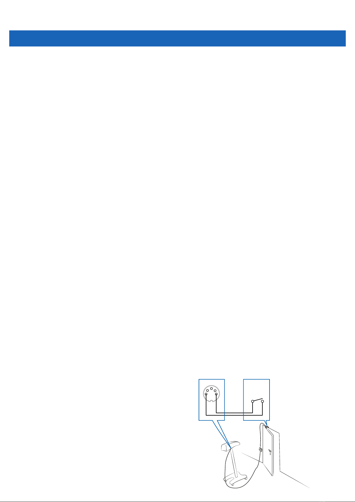
Interlock connection
The Opton BiPower Y2 features an interlock connector, positioned under
the body of the laser near the support.
This is a series contact and is connected to the door switch on the door
to the treatment room. The voltage of the connector is 12VDC.
N.B. With the exception of CO2models, which features a special connec-
tor for the patient button, the interlock can be connected to either of the
two connectors.
5.2 Safety
1 3
2
4 5
Fine corsa
limit

19
Laser warning
It is recommended that the machine is used in a well-lit room, without
reective surfaces, with the laser warning sign displayed at the entrance.
Therefore a warning sign featuring a ashing light is supplied.
Laser warning light
Protection
With regard to heat damage caused to tissues exposed to radiation, given
the power involved and the focusing systems used in Mectronic Medicale
devices, there is a real danger of heat damage which cannot be removed
without making the exposure values provided for by the protocols
impossible.
FOR THE USE OF LASER EQUIPMENT IT IS A LEGAL OBLIGATION TO
USE THE PROTECTIVE GLASSES SUPPLIED WITH THE MACHINE, COD.
651, OR EQUIVALENT WITH PROTECTION LEVEL IN TABLE.
The protective glasses supplied, cod. 651, don’t prevent the vision of
light signals.
We recommend to use the laser glasses supplied by Mectronic
Medicale.
The operator must constantly and carefully monitor the safety of the
patient during the treatment, thus avoiding any injury to the patient.
Protective glasses
Mectronic Medicale accepts no responsibility for damage or injury to
persons or property due to the incorrect use of its products or use of its
products which does not conform with the instructions supplied in the
user’s manual.
Code OD Protection
651 3 745-1115 DIR LB3
651 4 770-1100 DIR LB4
651 5 785-1085 DIR LB5
651 6 800-825 DIR LB6
651 6 885-1075 DIR LB6
651 7 1000-1070 D LB6+IR
LB7+M LB7Y
651 8 1030-1065 D LB6+IR
LB8+M LB7Y
651 6 9000-11000 DI LB3
651 1 0.01W 2E-6J 660-700 RB1
U S CE
Code OD Protection
659 3 630-1150 DIR LB3
659 4 670-1135 DIR LB4
659 5 680-1125 DIR LB5+M LB5Y
659 6 685-1115 DIR LB6+M LB6Y
659 7 725-1100 D LB6+IR LB7+M
LB7Y
659 8 735-1080 D LB6+IR LB8+M
LB7Y
659 6 9000-11000 DI LB3 U
659 3 1W 2E-4J 630-645 RB3 U
S CE
Protective glasses only with 650nm
20
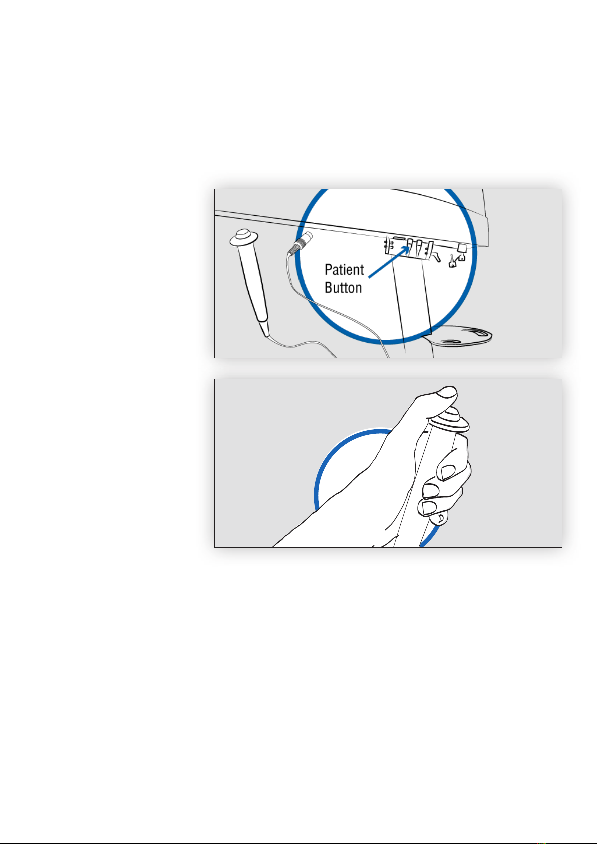
Patient Button
Models CO2(8000 C, Bi-Power 980, Bi-Power 810 and Bi-Power 1064)
feature a further safety system. Using the patient button, the treatment
can be interrupted at any time.
The button is connected to the connector on the bottom of the machine
body, labelled ‘Patient Safety’.
The button is used during operation of the Opton BiPower Y2. The patient
can interrupt the treatment at any time.
5.3 Patient safety
The button must be connected to
the connector on the bottom of the
main body, indicated by the label
“Patient Safety.”
The button is needed while Opton
BiPower Y2 is used on a patient.
The patient has the option to stop
therapy at any time.
This manual suits for next models
1
Table of contents
Popular Medical Equipment manuals by other brands

Mindray
Mindray WATO EX-55Pro Service manual

Huntleigh
Huntleigh Smartsigns Compact SC1000 Instructions for use

TransLite
TransLite Veinlite LED quick start guide

Harvest Healthcare
Harvest Healthcare HLB685 General User/ Safety Guide

Joerns
Joerns Hoyer HPL700 Service & parts manual

Enraf Nonius
Enraf Nonius ManuXelect manual


