Medem CM2M-K User manual

29/11/2017
CM2M-K
2 Channel Fan Current Monitor
• Dual channel current monitor.
• Coarse and fine sensitivity adjustment
• Range 30 m mps to 24 amps
• Reduces nuisance dropouts
CM2M-K Features
Note: These instructions are designed to be read in conjunction with those for a Medem control panel
which has ventilation interlock, herein referred to as the main panel.
The CM2M-K is a two channel current monitoring devices designed to monitor the power being drawn
by the ventilation and provides the interconnection to the main panel in order to correctly interlock the
ventilation.
It comprises two current monitor circuits & B and can therefore interlock two separate fans.
The maximum cable length between the CM2M-K and the main panel should not exceed 100 metres, whilst we would always
recommend using screened cable if the distance between the main panel and the detectors is greater than 20metres a 1mm
screened cable must be used on the +VE, 0v terminals
We recommend a six core screened Belden type security cable or 600v rated BMS cable (max cable length of 100meters.)
Warranty will be void if Fire Protection Cable or cable over 1mm dia. is used on the SELV side.
The CM2M-K must be installed before any speed controllers or inverters.
Mains rating: 240/440 V C 50HZ, 24 mps Maximum Continuous.
When using with a 3phase fan, wire one single phase only through the current monitor.
NOTE MAINS WIRING AND SIGNAGE MUST BE IN ACCORDANCE WITH CURRENT IEE WIRING REGULATIONS.
2
29/11/2017
CM2M-K
The CM2M-K is a current monitor designed for use with Medem ventilation interlock systems (main panel). It’s is connected via a
6 core low voltage cable.
There is a 12volt supply for the CM2M-K (from the main panel) the CM2M-K then provides 2 NC contacts L/B & L for connecting
to the main panel terminals S1 & E1 .
Each CM2M-K can be used to interlock 2 fans (sides & B), the fans are connected by taking the live feed for each fan through
the “Live In and Live Out” terminals (before any speed controllers/inverters), fan load sensitivity range on each fan is 30 milliamps
to 24amps.(max).
There are 3 LED indications,
1x Green, for the 12 volt power to the CM2M-K
2x Red, one for fan and another for Fan B load detection.
When the fans are switched on and the load is detected (see sensitivity adjustment) the corresponding side’s NC contact (L/B or
L ) will close and the red LED will light, this will flash for the first 15 minutes after current detection and then become solid. The
flashing LED helps to identify a fan intermittently stalling
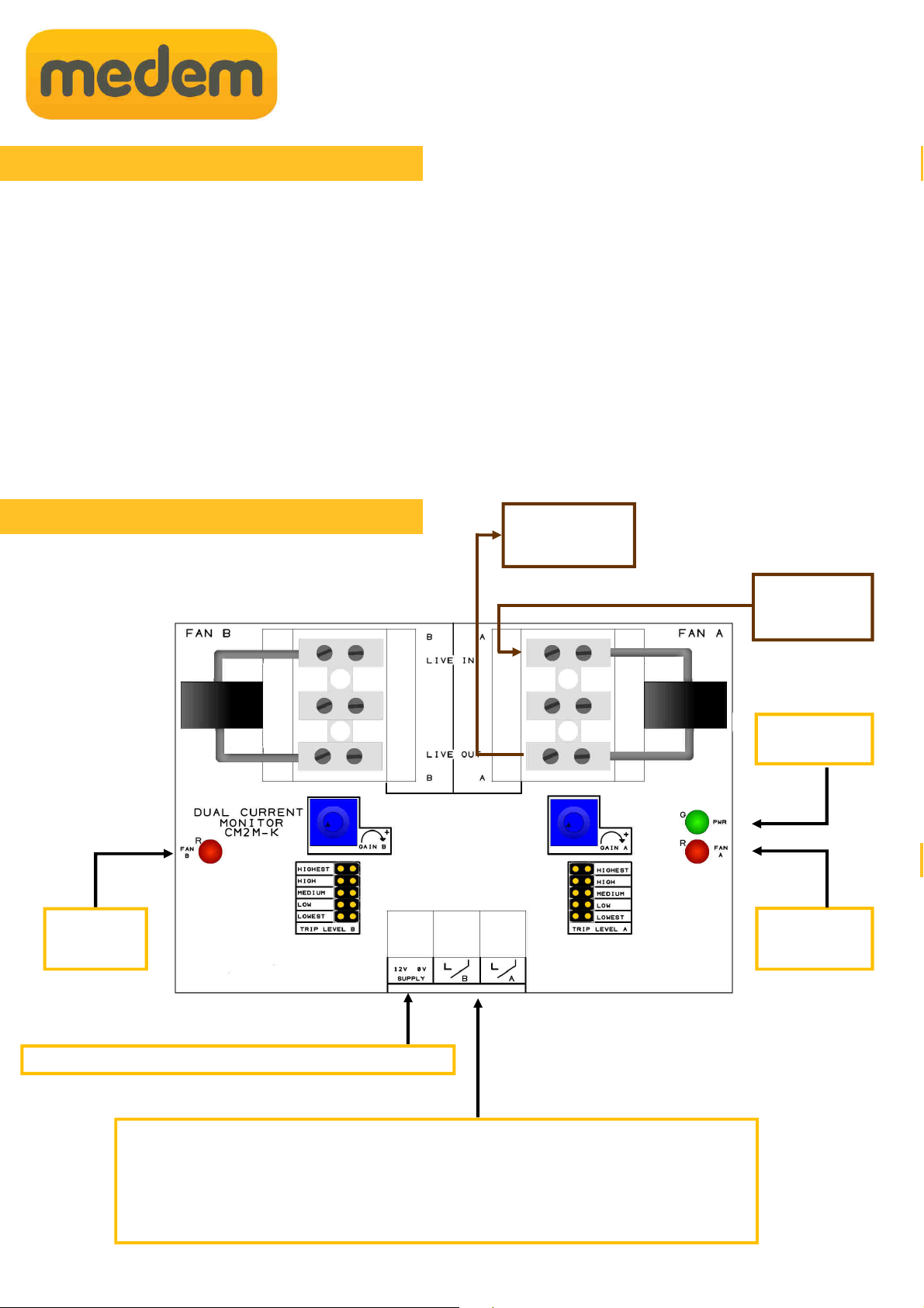
Terminal Connections
The LB & L terminals correspond to each side of the current monitor and provide a closed
contact, connect these back to the S1 or E1 terminals on the main panel.
Please note that when using more than one CM2M-K the signal connection should be in series.
Connect the 12 volt terminals back to the main panel 12v supply.
Fan
running LED
PCB Connections
Connections at the current monitor
Fan B
running LED
Power LED
Description and Operation
F N
Live Supply
F N
Speed Controller

3
29/11/2017
Mains Wiring
The live supply to one fan speed controller is connected through “one channel” ( or B) of the CM2M-K.
The “supply“ is taken in to “Live in” and back out via “Live out” and then connected to the speed controller.
This can then be repeated for another fan using the second channel.
Live feed through the
Medem CM2M-K channel current
Monitor
fans Fan speed
controls Fan live
Supply
Where using 3 phase fans
interlock on a single phase
6 core low voltage
+/- 12v Power
S1 = Supply Fan N/C contact
E1 = Extract Fan N/C contact
Fan Interlock Connections
CM2M-K Connections at the main panel
There is a fine adjustment using the potentiometer labelled “Gain” and a coarse adjustment by means of jumper
links.
The CM2M-K is set at its most sensitive (lowest current required) position.
By turning the potentiometer anti-clockwise, the amount of current required to operate the unit is increased.
To further increase the amount of current required to operate the unit, the jumper can be moved from the Lowest
Trip Level (smallest amount of current = most sensitive), to either the low, medium, high or highest trip level
setting (most amount of current = least sensitive).
Jumper link must be fitted on both channels course adjust setting, even if only one is being used
lways ensure that when the fan is switched off, the red LED goes out (this may take a few seconds).
Especially important on lighted canopies.
-
Sensitivity
+
Sensitivity adjustment
Course adjust
Fine adjust

4
29/11/2017
CM2M-K Commonly asked questions
• When installing with a three phase fan, interlock using just one phase of the fan.
• lways install the current monitor before any speed controllers or invertors.
• flashing green power LED indicates that a jumper link is missing from one of the “course sensitivity
headers”, both & B links must be fitted even if only using one side of the CM2M-K
• When a fan is first switched on and the power drawn is detected, the corresponding “Running LED” will flash
red for the first 15 minutes running and then become solid. This can be used to help diagnose a fan which is
intermittently cutting out.
• The current monitor will detect a current as low as 30m mps, if when the fans are switched on you do not
have a red flashing check the sensitivity adjustment hasn't been raised too high.
• Wire the connection for any supply air into the main panel terminals S1 and the extract air into E1, this will
allow correct reporting of the fans in the LCD screen.
• If you only have extract air/one fan installed (and connected to E1) leave the shorting link fitted into S1 to avoid
the main panel waiting for another fan start.
Warranty
Medem UK Warranty
Terms & Conditions
1. The warranty is a parts warranty and Medem UK Ltd will not cover or accept any labour or other expenses
that may be incurred in the process of changing faulty product.
2. ll panels and sender units are covered by a five year warranty.
3. Gas detector units and other remote detectors carry a two year warranty. Installation of the detectors should
not be undertaken until all building and construction work is completed.
4. Gas solenoid valves carry the original manufacturers warranty, though as the supplier Medem UK will
exchange faulty valves for return to the manufacturer.
5. Where a Medem UK engineer (or another company appointed by Medem UK) commission and installed
system then that system will carry a ten year warranty. This applies to the main panel and the sender unit. t
the time of commissioning a security label with a serial number will be attached to the main panel box.
photographs and a comprehensive record of the installation will be held by Medem UK.
6. Where a warranty claim is made then, where appropriate, a written order to attend site must be provided to
Medem UK cost for labour and travel to site will be prepared as a quote. The cost must be included in the
order.
7. Where it is found that the installation and/or the quality of workmanship has contributed to or wholly caused
the failure of the product then we reserve the right to charge the whole or a proportion of the cost of the faulty
item.
Table of contents


