Media MQ-1132 / SA User manual

MQ-1132 / SA Evaluation Board Users Guide MediaQ Incorporated
Board Revision 2
Revision A 4/12/01 Preliminary
MQ-1132 / SA Evaluation Board Users Guide
Board Revision 2

MQ-1132 / SA Evaluation Board Users Guide MediaQ Incorporated
Board Revision 2
Revision A 4/12/01 Preliminary
Introduction....................................................................................................................................................3
MQ-1132 Overview .......................................................................................................................................3
Platform Description......................................................................................................................................3
MQ-1132 Board Layout.............................................................................................................................3
MQ-1132 Board Layout.............................................................................................................................4
Connectors..................................................................................................................................................4
Switches/Potentiometers/Miscellaneous ....................................................................................................4
Jumpers.......................................................................................................................................................5
Platform setup instructions.............................................................................................................................5
Hardware Assembly...................................................................................................................................5
Software Download....................................................................................................................................6
Functional Description...................................................................................................................................7
Flat Panel Interface.....................................................................................................................................7
Touch Screen / MMC .................................................................................................................................8
USB............................................................................................................................................................8
Audio ..........................................................................................................................................................8
Power..........................................................................................................................................................8
Related Documentation..................................................................................................................................8
MQ-1132 / SA Evaluation Board Users Guide MediaQ Incorporated
Board Revision 2
Revision A 4/12/01 Preliminary
INTRODUCTION
This guide is intended to give a brief overview of the MQ-1132 and describe the features and workings of
the MQ-1132 / SA-1110 Evaluation Board. This includes how to locate connectors, configure switches,
configure jumpers, and the configuration of this evaluation board with the Intel StrongARM SA-1110
(Assabet) and SA1111 (Neponset) platform.
MQ-1132 OVERVIEW
The MQ-1132 is an integrated liquid-crystal display (LCD) and I/O controller with embedded memory for
low cost portable devices requiring long battery life and high performance. The MQ-1132 supports a
wide range of microprocessor interfaces including the Intel StrongARM SA-1110 Microprocessor. It has
a high bandwidth, 64-bit wide memory bus to embedded SRAM capable of bandwidths up to 192MB/S.
The MQ-1132 also integrates a high performance 2D graphics engine, LCD display interface, USB device
and host, Serial Peripheral Interface (SPI), I2S Audio Codec interface along with general purpose I/O and
LED pins.
PLATFORM DESCRIPTION
The MQ-1132 / SA Evaluation Board along with the Intel StrongARM SA-1110 Microprocessor
Development Platform can be used to exercise the various features provided by the MQ-1132 as well as
provide a development and verification platform for hardware and software.

MQ-1132 / SA Evaluation Board Users Guide MediaQ Incorporated
Board Revision 2
Revision A 4/12/01 Preliminary
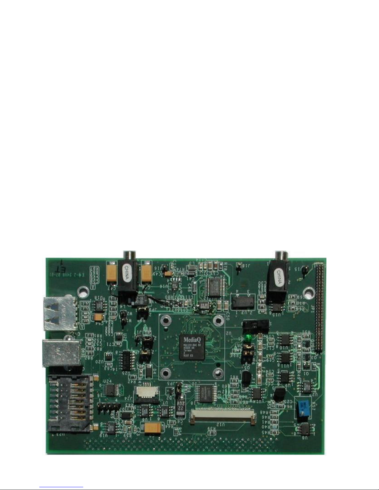
MQ-1132 Board Layout
The location of the connectors, jumpers, switches and adjustable potentiometers are shown on the layout
diagram below. These are described in the tables on the following pages.
Connectors
Reference
Type Description
U5 140-pin AMP P/N 536280-6 SA-1110 Assabet connector
U12 50-pin flex cable socket Sharp HR TFT connector
JP1 60-pin, 50 mil, 2x30, male
header Generic flat panel connector
J12 Phone jack Audio input connector
J13 Phone jack Audio output connector
CN1-1 USB type B USB type B device connector
CN2-1 USB type A USB type A host connector
J23 4-pin, 1x4, 0.1” header Generic Touchscreen connector
J24 4-pin flex cable socket Touchscreen connector for Sharp HR TFT
U23 MMC Multi Media Card socket/connector
Switches/Potentiometers/Miscellaneous
Reference
Type Description
SW1 SPST Switch Powerdown switch (1-2 normal, 2-3 powerdown CPU I/F)
R57 Potentiometer (50K)
D1 LED Used to test GPIO 54 functionality
USB
HOST
USB
DEVICE
MMC
MQ-
1132
Generic FP
Sharp HR TFT
CN2
CN14
U23
J23 U12
J13 J12
JP1
SW1
U2
R57
J24
U5
D1
SA-1110 I/F
AUDIO
IN
AUDIO
OUT
1
1
JP6
JP5
JP4
JP7
JP9
JP8
1
1
2

MQ-1132 / SA Evaluation Board Users Guide MediaQ Incorporated
Board Revision 2
Revision A 4/12/01 Preliminary
Jumpers
Reference
Type Description
JP4, JP5
JP6, JP7,
JP8, JP9
2-pin, 1x2,
0.1” header Power measurement jumpers for FVDD (flat panel), BVDD (Bus),
USBVDD (USB), AVDDOSC (Oscillator I/O ESD), CVDD13 (SRAM)
and CVDD24 (Core). Normal operation requires either these jumpers or
resistors R93, R94, R95, R96, R97 and R98 installed. Both jumper and
associated resistor removed when measuring power.
PLATFORM SETUP INSTRUCTIONS
The MQ-1132 / SA-1110 Evaluation Board is used in conjunction with the Intel StrongARM SA-1110
Reference Platform. The following components are required and should be included in the Intel
SA1110/SA1111 development package:
§SA-1110 platform module (Assabet)
§SA-1111 developer platform module (Neponset)
§DC supply for platform
§Compact flash Ethernet card, CF to PCMCIA adapter and crossover cable
§Serial cable (10-pin female header to 9-pin female serial port connector)
Please note that no compact flash adaptor should be installed in the SA1110 board socket, as it will cause
damage to the card and the bus drivers used to drive the MQ1132 & SA1111 board’s bus.
Hardware Assembly
The SA-1110 platform has two 140-pin connectors, J2 and J3. J2 interfaces with the SA-1111
Development Module while J3 interfaces to the MQ-1132 evaluation board. The final assembly should
resemble the diagram below which is a side view of the Intel StrongARM platform and MQ-1132
Evaluation Board. Great care should be taken to ensure correct alignment of the sockets and plugs to
prevent damage during assembly. When removing either the MQ1132 or SA1111 boards, great care
should be taken to ensure that even pressure is asserted on both sides of the connector to prevent damage
to the Plug pins and moldings.
Power is supplied to the SA-1110 Development Board connector J10. Power for the MQ-1132 board is
supplied from the SA-1110 main 140-pin bus connector.
SA-1111 Module
SA-1110 CPU Board
MQ-1132 Evaluation Board
Table of contents


