Medora GridBee SN15 User manual

© 2020 Ixom | www.medoraco.com | 866 - 437 - 8076 | [email protected]
O&M_SN15_10030_20200619
GridBee SN15
Owner's Manual

Table of Contents
About Ixom
Ixom combines knowledge and experience from across the water quality spectrum to help solve
real-world problems. Whether in Lakes, Stormwater Retention Ponds, Raw Drinking-Source Reservoirs, Water
Treatment Plants, Potable Storage Tanks, or Wastewater Treatment Processes, Ixom equipment continues to
be at the forefront as the #1 world leader for in-situ water body treatment.
© 2020 Ixom | www.medoraco.com | 866 - 437 - 8076 | [email protected]
Table of Contents
10014_20200528
GridBee SN15
Owner's Manual
Safety 1
Placement 4
Electrical 6
Startup and Operation 8
Troubleshooting 9
Technical Specifications 10
Exploded Parts Diagram 11
Dimension Drawing 12
Warranty 13
Customer Service 14
O&M_SN15_10030_20200619

Carefully read safety information when you see
any safety symbols.
Be sure you have read all installation, operation, maintenance and safety instructions before
you install, service or begin to operate this unit.
Accidents occur every year because of careless use of industrial equipment. You can avoid hazards
by following these safety instructions, and applying some ordinary common sense when operating or
servicing this unit.
Keep in mind that full operator attention and alertness are required when operating or servicing
this unit.
USE COMMON SENSE!! Most accidents can be avoided by using common sense and
concentration on the job being done.
© 2020 Ixom | www.medoraco.com | 866 - 437 - 8076 | [email protected]
Safety
Safety
1949_10036_20200528 O&M_SN15_10030_20200619 - 1

IMPORTANT!!!
Follow all federal and state laws in regards to
safety regulations of working at heights, conned
spaces, rescue, etc. as required by the U.S.
Department of Labor, Occupational Safety and
Health Administration. Use necessary PPE when
placing and servicing this unit.
Identify all possible hazards. Determine what
safeguards are needed and implement them.
Only you, the user, understand your product
and system characteristics fully. The ultimate
responsibility for safety is with you. Your
safety ultimately rests in your hands. Do
your part and you will enjoy safe, trouble free
operation for years to come. This instruction
manual is not intended to include a
comprehensive listing of all details for all
procedures required for placement, operation
and maintenance. If you have a question about
a procedure or are uncertain about any detail,
Do Not Proceed. Please contact Ixom
Customer Service at 866-437-8076 to speak
to a representative.
ELECTRICAL HAZARD
WARNING: THIS EQUIPMENT CONTAINS
HIGH VOLTAGE! ELECTRICAL SHOCK CAN
CAUSE SERIOUS OR FATAL INJURY. ONLY
QUALIFIED PERSONNEL SHOULD ATTEMPT
PLACEMENT, OPERATION AND MAINTENANCE
OF ELECTRICAL EQUIPMENT. REMOVE ALL
SOURCES OF ELECTRICAL POWER BEFORE
PERFORMING ANY SERVICE WORK TO THE
MACHINE. USE PROPER LOCKOUT TAGOUT
(LOTO) PROCEDURES TO ENSURE A SAFE
WORK ENVIRONMENT.
Rotating Hazard
CAUTION: KEEP BODY APPENANDAGES OR
LOOSE CLOTHING AWAY FROM EQUIPMENT
WHILE OPERATING. ENSURE EQUIPMENT IS
OFF BEFORE ATTEMPTING SERVICE.
Crush Hazard
WARNING: DO NOT REMOVE ANY FLOAT
ASSEMBLY BOLTS OR PINS WHILE EQUIPMENT
IS FLOATING IN WATER. EQUIPMENT MUST BE
SECURELY SUPPORTED BEFORE PERFORMING
SERVICE.
Laceration Hazard
CAUTION: EDGES MAY BE SHARP AND CAUSE
LACERATION IF PROPER CARE IS NOT USED.
Entanglement Hazard
WARNING: ENSURE THAT PERSONNEL ARE
CLEAR OF THE ELECTRIC CORD AND CHAIN TO
AVOID ENTANGLEMENT.
Thin Ice Hazard
WARNING: ICE SURROUNDING MACHINE MAY
NOT SUPPORT WEIGHT, KEEP CLEAR OF THIN
ICE.
© 2020 Ixom | www.medoraco.com | 866 - 437 - 8076 | [email protected]
Safety
Safety
1949_10036_20200528 O&M_SN15_10030_20200619 - 2

Permit-Required
Conned Spaces
A conned space has limited openings for
entry or exit, is large enough for entering and
working, and is not designed for continuous
worker occupancy. Conned spaces include
underground reservoirs, ground storage tanks,
elevated tanks, silos, manholes, and pipelines.
Conned Space Tips
• Do not enter permit-required conned spaces
without being trained and without having a
permit to enter.
• Review, understand and follow employer’s
procedures before entering permit-required
conned spaces and know how and when
to exit.
• Before entry, identify any physical hazards.
• Before and during entry, test and monitor for
oxygen content, ammability, toxicity or
explosive hazards as necessary.
• Use fall protection, rescue, air monitoring,
ventilation, lighting and communication
equipment according to entry procedures.
• Maintain contact at all times with a trained
attendant either visually, via phone, or by
two-way radio. This monitoring system
enables the attendant and entry supervisor
to order you to evacuate and to alert
appropriately trained rescue personnel to
rescue entrants when needed.
Refer to 29 CFR 1910.146 for complete
regulations set by OSHA. Refer to your state's
regulations if your state established and operates
their own safety and health programs approved
by OSHA.
Protect Yourself
It is important that you comply with all relative
OSHA and local regulations while installing
and performing any maintenance to the mixer
circulation equipment.
Key OSHA Compliance Standards that must
be followed (and not limited to) are:
• 1910.146 Permit-required conned spaces
• 1910.147 Lockout/Tagout
• 1926.500 Fall Protection
Fall Protection Tips
• Identify all potential tripping and fall hazards
before work starts.
• Look for fall hazards such as unprotected
oor openings/edges, shafts, open hatches,
stairwells, and roof openings/edges.
• Inspect fall protection and rescue equipment
for defects before use.
• Select, wear, and use fall protection and
rescue equipment appropriate for the task.
• Secure and stabilize all ladders before
climbing.
• Never stand on the top rung/step of a ladder.
• Use handrails when you go up or down stairs.
• Practice good housekeeping. Keep cords,
welding leads and air hoses out of walkways
or adjacent work areas.
Refer to 29 CFR 1926.500 for complete
regulations set by OSHA. Refer to your state's
regulations if your state established and operates
their own safety and health programs approved by
OSHA.
Lockout Tagout
When the On/Off switch is in the "ON" position,
the mixer may start up at any time if not already
operating. The mixer's On/Off switch can be
locked out by placing a pad lock thru the door latch
of the controller after the switch has been turned
to the "OFF" position. The On/Off switch is to be
used as the emergency stop.
© 2020 Ixom | www.medoraco.com | 866 - 437 - 8076 | [email protected]
Safety
Safety
1949_10036_20200528 O&M_SN15_10030_20200619 - 3

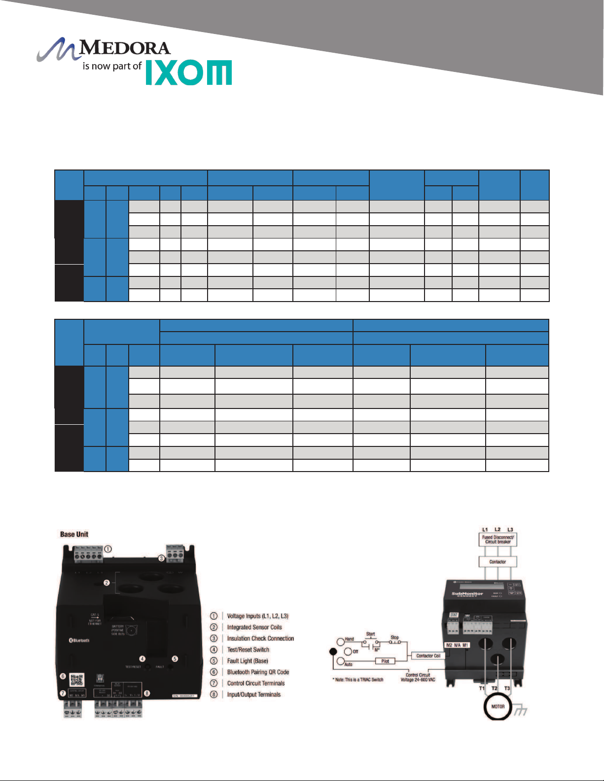
Control Panel Secondary Disconnect
& Tank Penetration
Source Power
SN Machine
Submersible cable ran from tank penetration to
SN machine.
Electrical conduit ran to top of tank, 4
Conductors sized according to NEC.
Spray system installed through hatch. Tethered
with dual tether system
Electrical Control Panel located at bottom of
tank.
Blower placed over top of machine.
Blower size depends on tank specics and
application. (Blower shown as roof mount,
certain models may require ground mount.)
Machine safety disconnect located near tank
entry
© 2020 Ixom | www.medoraco.com | 866 - 437 - 8076 | [email protected]
Placement
Placement Overview
SN Large Frame Series
10041_20200221 O&M_SN15_10030_20200619 - 4

FRONT VIEW SN DUAL TETHERING
TOP VIEW SN DUAL TETHERING
ROOF CONNECTION DETAIL
4” Diameter Chain Loop
316 Stainless Steel Chain
Approx. 6”
MOORING CONNECTION DETAIL
© 2020 Ixom | www.medoraco.com | 866 - 437 - 8076 | [email protected]
SN Machine
Dual Tethering
Visual Dual Tethering
SN Large Frame Series
2001_10142_20200221 O&M_SN15_10030_20200619 - 5
Three Phase Motor Specications (60 Hz) 3450 RPM:
TYPE
RATING FULL LOAD MAXIMUM LOAD LINE TO LINE
RESISTANCE
OHMS
EFFICIENCY LOCKED
ROTOR
AMPS
KVA
CODE
HP KW VOLTS HZ S.F. AMPS WATTS AMPS WATTS S.F. F.L.
4” STD
5 3.7
200 60 1.15 18.3 4800 20.5 5500 .68-.83 78 78 116 K
230 60 1.15 15.9 4800 17.8 5500 .91-1.1 78 78 102 K
460 60 1.15 8.0 4800 8.9 5500 3.6-4.4 78 78 53.7 K
6 ” STD.
10 7.5
230 60 1.15 28.4 9400 32.2 10800 .47-.57 79 79 172 H
380 60 1.15 17.6 9400 19.6 10800 1.2-1.5 79 79 104 H
460 60 1.15 14.2 9400 16.1 10800 1.9-2.4 79 79 86 H
15 11 380 60 1.15 25.8 13700 28.9 15800 .77-.95 81 81 161 H
460 60 1.15 20.8 13700 23.7 15800 1.1-1.4 81 81 133 H
TYPE
RATING CIRCUIT BREAKERS OR FUSE AMPS CIRCUIT BREAKERS OR FUSE AMPS
(MAXIMUM PER NEC) (TYPICAL SUBMERSIBLE)
HP KW VOLTS STANDARD
FUSE
DUAL ELEMENT
TIME DELAY FUSE
CIRCUIT
BREAKER
STANDARD
FUSE
DUAL ELEMENT
TIME DELAY FUSE
CIRCUIT
BREAKER
4” STD &
HI-TEMP
5 3.7
200 60 35 50 60 25 50
230 50 30 40 45 20 40
460 25 15 20 25 10 20
6 ” STD.
10 7.5
230 90 50 80 90 40 80
380 60 35 45 50 25 45
460 45 25 40 45 20 40
15 11 380 80 50 70 80 35 70
460 70 40 60 60 30 60
Three Phase Submersible Motor and Pump Protection Wiring
© 2020 Ixom | www.medoraco.com | 866 - 437 - 8076 | [email protected]
Electrical
Three Phase Wiring for THM SN Spray Units
1584_10037_20200619 O&M_SN15_10030_20200619 - 6

TANK PENETRATION IS SEALED WITH
HDPE WASHERS ACCOMPANIED BY
LEXEL® CO-POLYMER RUBBER-BASED SEALANT
CROSS-SECTIONAL VIEW
METAL TANK ROOF
INSIDE TANK
OUTSIDE TANK
ELECTRIC CABLE
1 CORD BOLT PER GRIDBEE:
NUT/GASKET OD: 2.250”
THREADED FIXTURE OD: 1.250”
BORE REQUIRED: 1.3125”
WASHER SEAL, HDPE
STRAIN RELIEF
WASHER
BRASS NUT
316SS UNIVERSAL
FIXTURE
(3/4” NPT FEMALE
THREADS FOR CONDUIT
CONNECTION POINT)
BRASS NUT
T316SS 3/4” MNPT
GLAND SEAL
316SS QUICK LINK
MESH STRAIN RELIEF
INSIDE
TANK
OUTSIDE
TANK
WASHER SEAL, HDPE
MAXIMUM BEARING
THICKNESS: 3.125 INCHES
NOT DESIGNED AS A
SUBMERSIBLE PENETRATION.
© 2020 Ixom | www.medoraco.com | 866 - 437 - 8076 | [email protected]
Electrical
Universal Fixture Assembly
Tank Penetration
1988_10121_20200221 O&M_SN15_10030_20200619 - 7

Placement Checks
Before starting the SN Spray Unit a few checks need to be done to conrm the placement is correct.
Placement Check Check
Is the SN Spray Unit properly tethered? (Assembly)
Is the cord ran through the cord seal and cord seal tightened at the interior of the cord xture? (Assembly)
Is the top splice between submersible cable conductors and exterior electric conductors insulated from each
other and individually sealed to protect from corrosion? (Assembly)
Is the control panel wired correctly? (Control Panel Diagram)
Is the SN Spray Unit submerged within the minimum water depth required? (Technical Specications)
Is the Motor rotating the correct direction? (See Rotation Check below)
Check Reading
Single Phase Three Phase
Continuity Check (Motor Windings + Splice + Wire)
Reference Wiring for Line to Line Ohms
L1:L2 L1:L2 L2:L3 L1:L3
Discontinuity Check (Power to Ground)
Should be Open to Ground
L1: GND L1: GND L2:GND L3:GND
Source Voltage Reading (while unit is running) L1:2 L1:2 L2:L3 L1:L3
Amperage Reading (while unit is running)
Reference Wiring Full Load / Max Load
L1 L1 L2 L3
Flow Check Auditory
Flow Check Visual
Final Checks
Now that the install checks have been completed. Now to conrm the continuity and discontinuity and then
start the SN Spray Unit.
Rotation Check - (Three Phase Only)
Before nalizing the placement, the motor rotation needs to
be checked. With someone observing the SN Spray Unit,
briey turn the unit on for several seconds and observe the
ow pattern, look for how far out the spray reaches. Turn unit
off, isolate power, and have a qualied person switch 2 of the
3 motor leads of outgoing power. Repeat operation again for
several seconds and observe the SN Spray Unit ow pattern
again. Determine which wiring conguration produced the
ow pattern that reaches out the furthest and nalize with that
wiring of the outgoing power leads. See Figure 1 for proper
ow direction. Figure 1: Flow Check
REVERSEFWD FWD
© 2020 Ixom | www.medoraco.com | 866 - 437 - 8076 | [email protected]
Startup and Operation
SN Startup and Operation
Wiring
10103_20200221 O&M_SN15_10030_20200619 - 8
Operation
For suspected issues regarding SN Spray Unit operation, observing and recording motor current and voltage
during operation is a good starting point. The normal operating values can be referenced from initial Startup &
Operation records and/or from the Wiring document. In addition to motor voltage and current measurements,
with power isolated, continuity (ohm) value measurements are helpful in pinpointing issues.
Check Reading
Flow Check Visual
Flow Check Auditory
Electric measurements should only be performed
by qualied personnel
Single Phase Three Phase Only
Source Voltage Reading (while unit is running) L1:L2 L1:L2 L2:L3 L3:L1
Amperage Reading (while unit is running)
Reference Wiring Full Load / Max Load
L1 L1 L2 L3
Continuity Check (Motor Windings + Splice + Wire)
Reference Wiring for Line to Line Ohms
L1:L2 L1:L2 L2:L3 L3:L1
Discontinuity Check (Power to Ground)
Should be Open to Ground
L1: GND L1: GND L2:GND L3:GND
Figure 1: Flow Check
REVERSEFWD FWD
Symptom Possible Issue / Remediation
Motor Amperage is low Blocked pump inlet screen, clean debris from inlet
Blocked spray nozzle(s), clean spray nozzle(s)
Broken, severely worn coupling between pump and motor,
pump and/or motor replacement
Motor Amperage is high Low / Unbalanced line voltage, check source power
Phase loss, check source power
Short to ground, check continuity to ground leads, bad electric
cord, splice, or motor failure, replace faulty component(s)
Motor or pump failure, replace motor and/or pump
Fault Message from Three-Phase Motor
Protection device
Reference motor protection device manual for detailed
problems/conditions resulting in fault message.
Rotation Check - (Three Phase Only)
If wiring was disconnected during troubleshooting steps, the
motor rotation needs to be checked. With someone observing
the SN Spray Unit, briey turn the unit on for several seconds
and observe the ow pattern, look for how far out the spray
reaches. Turn unit off, isolate power, and have a qualied
person switch 2 of the 3 motor leads of outgoing power.
Repeat operation again for several seconds and observe the
SN Spray Unit ow pattern again. Determine which wiring
conguration produced the ow pattern that reaches out the
furthest and nalize with that wiring of the outgoing power
leads. See Figure 1 for proper ow direction.
© 2020 Ixom | www.medoraco.com | 866 - 437 - 8076 | [email protected]
Troubleshooting
SN Troubleshooting
1981_10044_20200527 O&M_SN15_10030_20200619 - 9
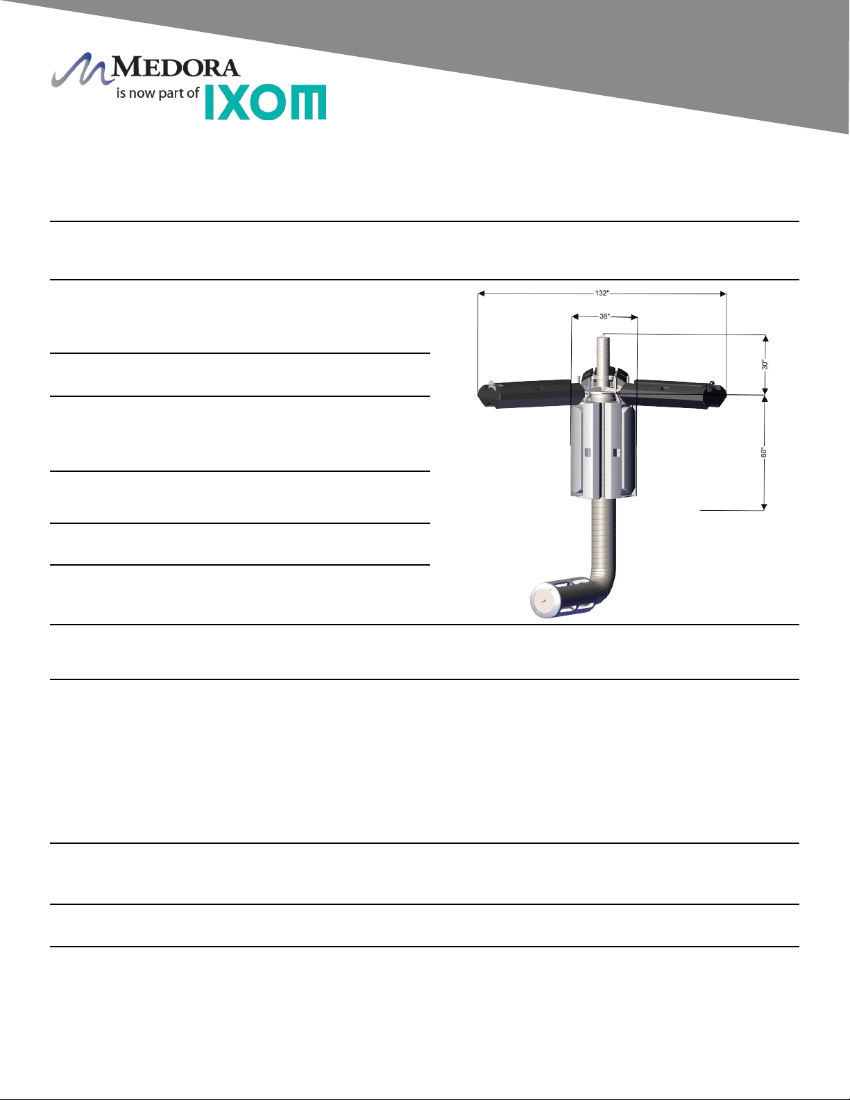
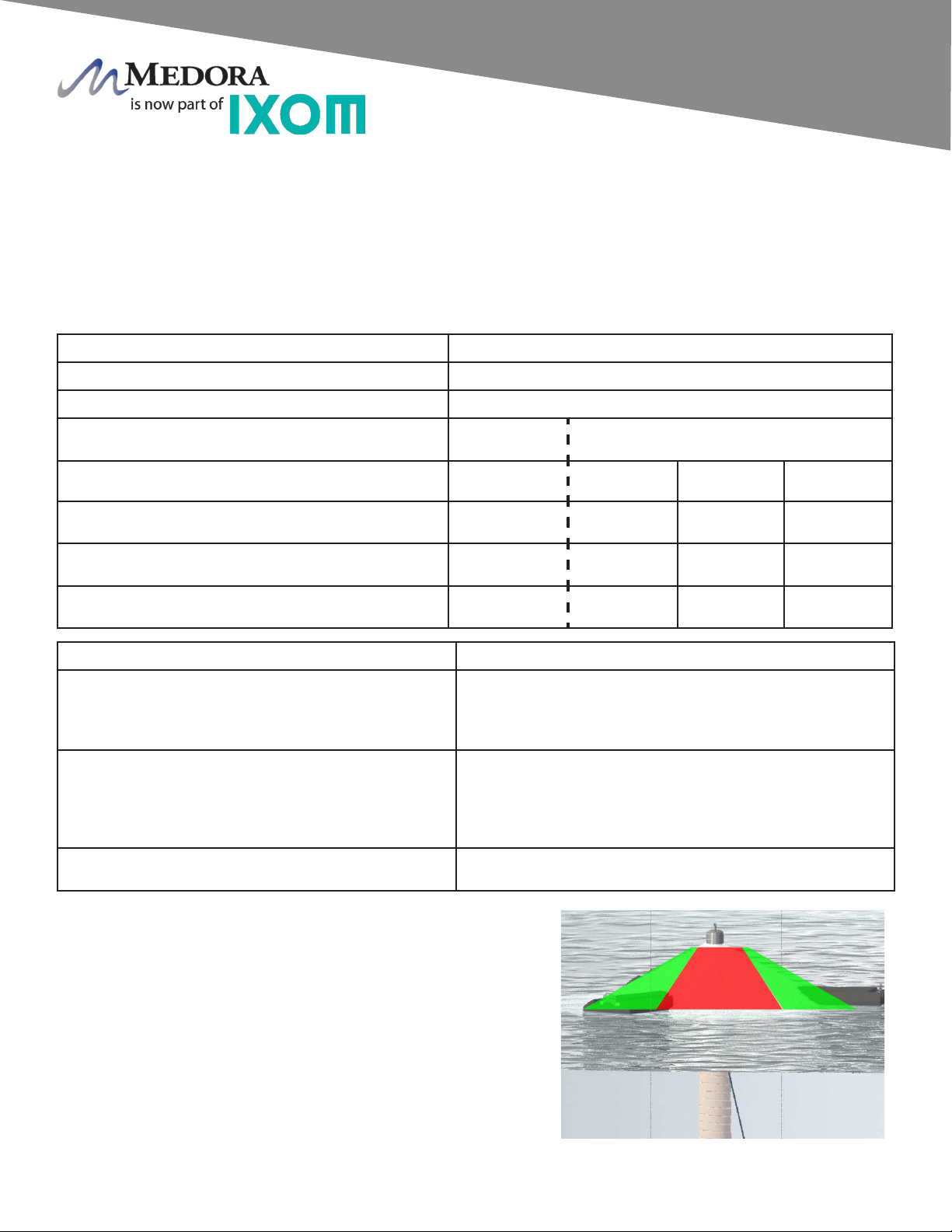
Technology Description- Floating, electric powered, circulation and Trihalomethane (THM) removal equipment for
potable water tanks and reservoirs. Designed for continuous operation and Factory installed through 24-inch diameter,
clear and unobstructed hatch opening.
Figure 1: SN15
Electrical Requirements - Requires 480VAC/3PH, 60Hz power. Ixom recommends secondary disconnect to be
located near equipment access hatch. Optional Franklin SubMonitor Connect three-phase motor protection unit highly
recommended and available from Ixom. All switches, breakers, emergency stop buttons, control panels and other controls
shall be installed in accordance to all NEC, State, and local regulations. (Not supplied by Ixom)
Patent Pending Subject to change without notice.
Certications - Ixom’s potable water products are certied to ANSI/NSF Standard 61, and 372 for lead-free content.
Learn more at: www.medoraco.com/std61
Maintenance / Warranty - Limited maintenance. Limited 2-year parts and labor warranty. See Warranty Statement for
details.
Spray Unit Direct Flow Rate - 1.1 Million Gallons Per Day,
MGD. Ixom application engineering evaluations often require
sizing systems based on site specic conditions and NOT
the spray aeration direct ow rate.
Minimum Water Depth - Minimum of 5ft (1.5m) operating
depth required, do not operate out of water.
Minimum Head Space - Minimum of 30in (76cm) head space
between water level and reservoir/tank ceiling required.
(Contact Ixom for exceptions that can be made.)
Sealed Penetration Fitting - T316 stainless steel tank tting with a 3/4” NPT female connection. Not designed
as a submersible penetration.
Wiring - 4-conductor, submersible power cable for submersible motor wiring terminated exterior at top of tank.
Motor - 15HP stainless steel submersible, designed for continuous operation, low power requirement, direct drive,
no gearbox and no lubrication schedule required. See certications section below.
Materials of Construction - T316 stainless steel,
thermoplastic rubber, High Density Polyethylene construction.
GridBee® Machines are constructed using safe materials for
contact with potable water. See certications section below.
TTHM Reduction Range - Dependant on THM Species,
Daily Inow and other variables, see Ixom for proposal.
Minimum Access Opening - Machine can be placed
through 24-inch (61 cm) diameter, clear and unobstructed
hatch opening.
Intake - 20 to 100+ feet (6 to 30+ m) available in 12-inch (30.5 cm) diameter X 20 feet (6 m) sections, thermoplastic
rubber, NSF/ANSI 61 approved. Includes low elevation intake that draws water in a horizontal layer within 18 inches
(45 cm) of the tank or reservoir oor. Includes intake retrieval chain constructed of 316 stainless steel.
Shipping Size / Weight
• Crate - 72in x 48in x 59in (1.85m x 1.22m x 1.5m) / 1200lbs (550kg) Exact weight and dimensions varies dependent
on machine conguration.
© 2020 Ixom | www.medoraco.com | 866 - 437 - 8076 | [email protected]
Technical Data Sheet
SN15
1555_10015_20200422 O&M_SN15_10030_20200619 - 10
General Notes:
1. PN: 100688 - 3DX Spray Nozzle Assembly
2. PN: 16013206 - Groove Coupling 6”
3. PN: 100211 - Discharge Pipe 6”
4. PN: 20013017 - SN15 Pump
5. PN: 20013019 - SN15 Motor (460vAC/3-Phase)
6. PN: 100541 - Platform Assembly
7. PN: 100284 - Collapsible Float
8. PN: 100395 - Float Arm
9. PN: 26061220 - NSF Hose 12” x 20’
10. PN: 16013107 - Hose Clamp 12” (2 - 6” Clamps)
11. PN: 101464 - Intake Assembly
08 01
06
10
09
07
05
04
02
03
10
11
© 2020 Ixom | www.medoraco.com | 866 - 437 - 8076 | [email protected]
Exploded Parts Diagram
SN15
Exploded Parts Diagram
1581_10039_20200221 O&M_SN15_10030_20200619 - 11
© 2020 Ixom | www.medoraco.com | 866 - 437 - 8076 | [email protected]
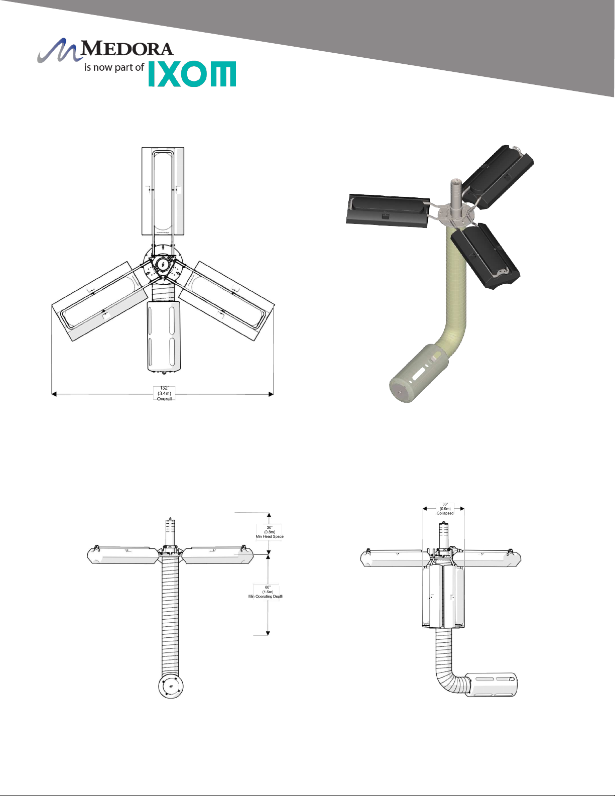
Dimension Drawing
SN15
Dimension Drawing
1552_10034_20200221 O&M_SN15_10030_20200619 - 12

GridBee SN Spray Units. GridBee SN Spray Units and blowers are warranted to be free of defective
parts, materials, and workmanship for a period of two years from the date of purchase. The optional
control panels, by other manufactures, are covered by a manufacturer’s warranty of one year from
date of purchase. This warranty is valid only for use of the GridBee THM Removal System in
accordance with the owner’s manual and any initial and ongoing factory recommendations. This
warranty is limited to the repair or replacement of defective components only and does not apply to
normal wear and tear. If the factory’s service crews performed the original on-site placement and
startup, then this warranty also includes labor. Where labor is included, in lieu of sending a factory
service crew to the site for minor repairs, Ixom may choose to send the replacement parts to the
owner postage-paid and may pay the owner a reasonable labor allowance, as determined solely by
Ixom, to install the parts. There is no liability for consequential damages of any type. The warranty
that is submitted and provided with the purchased equipment is the valid warranty.
GridBee control panels, and any optional accessories. These items are considered “buyout”
items for Ixom, and as such include a warranty against defects in material and workmanship for one
year from the date of purchase. This warranty covers parts only, not labor. Parts that are determined
by Ixom to be defective in material or workmanship under normal use during the one year warranty
period will be repaired or replaced. Shipping charges are the responsibility of the customer.
Terms applicable to all equipment. This Limited Replacement Warranty is subject to the terms of
Ixom’s General Terms and Conditions of Sale. In the event of any inconsistency between the terms
of this Limited Replacement Warranty and Ixom’s General Terms and Conditions of Sale, the terms of
this Limited Replacement Warranty shall prevail to the extent of that inconsistency.
© 2020 Ixom | www.medoraco.com | 866 - 437 - 8076 | [email protected]
Warranty
GridBee THM Removal Systems Limited Replacement Warranty
1683_10035_20200420 O&M_SN15_10030_20200619 - 13

Ixom employs qualied highly trained Service and Placement Technicians certied to perform the
necessary tasks required to install or remove SolarBee and GridBee circulation equipment
Ixom's specialized Service and Placement Technicians are trained in Conned Space, Fall Protection,
and other related subjects as required by OSHA to perform the necessary work to install or remove
SolarBee and GridBee equipment, and are knowlegeable in the regulations and standards of OSHA.
If you feel the need to service your SolarBee or GridBee circulation equipment, please contact Ixom's
Customer Service Department at:
+1 866 437 8076
Ixom Service & Support
© 2020 Ixom | www.medoraco.com | 866 - 437 - 8076 | [email protected]
Service & Support
1928_10001_20200420 O&M_SN15_10030_20200619 - 14
Table of contents
Popular Paint Sprayer manuals by other brands

StartingLine
StartingLine SB-2-610-G instruction manual

3M
3M Scotchkote HSS-450 User instructions

Electro Spray
Electro Spray 3WBJ-8M11 operating instructions

Graymills
Graymills Tempest T-10 Operation and maintenance instructions

WAGNER
WAGNER Super Finish 21 operating manual

Parkside
Parkside 87779 Operation and safety notes

C.A. Technologies
C.A. Technologies Jaguar 300H Product information

Graco
Graco Finex 24C308 instructions

KIRKLAND
KIRKLAND Orvin Mounted Single Sprayer Use and maintenance manual

Hyundai
Hyundai HSPA800-AC Original instructions

IMC
IMC IMCNL-HD-PY02 Series Operation manual

Titan
Titan Skid Basic owner's manual


