Megalarm MEGA 2550 User manual

MEGA 2550
2-WAY LCD PAGER ALARM
Installation Manual
MEGATRONIX
CHATSWORTH, CA USA
MEGA 2550 INSTALL 1

MEGA 2550 INSTALL 2

INSTALLATION DIAGRAM
H1: Main 5 Pin White Harness
H8: 10 Pin White Mini Connector
LED Indicator
Valet Switch
H4 6 Pin
White
H6 4 Pin
Orange
H3 2 Pin
Blue
H5 2 Pin
White
H7 4 Pin
Black
Dual Zone
Shock
Sensor
H1 5 Pin
White
H8 10 Pin
White
H4: 6 Pin Door Lock / Unlock
Wire Harness
Two Way
Transceiver
Antenna H2 3 Pin
Brown
Optional
pager(knock)
senso
r
H1: MAIN 5 PIN WIRE HARNESS:
5. Red Wire: +12V To Constant Batter
y
Source
4. Brown Wire: Positive out
p
ut To Siren
3. Black Wire: Ground to Vehicle Frame
2. White Wire: Parking Light Relay Output
1. Red / White Wire: Parking Light Relay Power Input
3A Fuse
10A Fuse
H8: 13 PIN MINI CONNECTOR WIRE HARNESS:
4. Green Wire: Zone 3 / Negative Door Pin Trigger Input.
2. Blue / White Wire: Zone 2 / Instant Trigger Ground Input
3. Violet Wire: Zone 3 / Positive Door Pin Trigger Input
1. Yellow Wire: Zone 5 / To Ignition Switched + 12V
5. Orange Wire: (-) 200mA Grounded Output When Armed
7. Light Green / Black Wire: (-) 200mA 2-Step Door Unlock Output.
9. Red / White Wire: (-) 200mA Channel 3 (Trunk) Output
10. Black / White Wire: (-) 200mA of Dome Light Output
6. Brown / Black Wire: (-) 200mA Horn Output
+12V
+12V
8. Purple / Black Wire: (-) 200mA Timer Controlled Channel 4 Output
MEGA 2550 INSTALL 3

Keep wiring away from moving engine parts, exhaust pipes, and high-tension cable. Tape wires that pass
through holes on the firewall to prevent frying electrical. Watch out for sharp edges that may damage wires
and causes short circuit.
CAUTION: Do not connect the wire harness to the control module until all wiring to vehicle is complete.
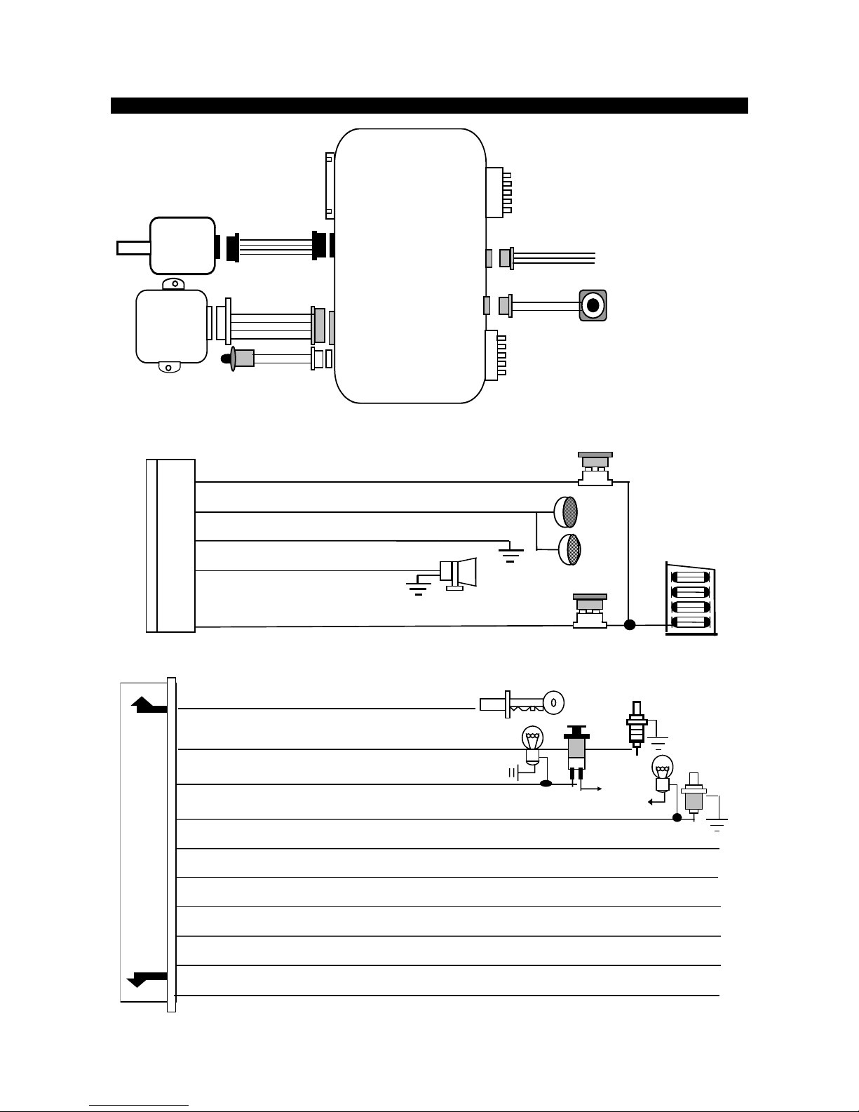
H1. MAIN 5 PIN WIRE HARNESS:
H1/1. Red / White Wire – Parking Light Relay Input –
The RED/WHITE wire is the input to the flashing parking light relay. The connection of the RED/WHITE
wire will determine the output polarity of the flashing parking light relay.
If the vehicle you are working on has +12volt switched parking light, you do not need to connect this wire.
This wire already is connected to +12volt.
If the vehicles parking light is ground switched, cut the RED/WHITE wire and connect the RED/WHITE
wire to chassis ground.
H1/2. White Wire – Parking Light Relay Output (+12 V 10A Output) –
Connect the WHITE wire to the parking light wire coming from the headlight switch. Do not connect the
WHITE wire to the dashboard lighting dimmer switch (Damage to the dimmer will result). The limitation of
the WHITE wire is 10 Amps max. Do not exceed this limit or damage to the alarm and parking light relay
will result.
H1/3. Black Wire – System Ground –
This is main ground connection of the alarm module. Make this connection to a solid section of the
vehicle frame. Do not connect this wire to any existing ground wires supplied by the factory wire loom.
Make the connection to the vehicle's frame directly.
H1/4. Brown Wire – Siren Drive or Horn Output – (Set Feature III – 2 Programming)
SIREN DRIVE OUTPUT (Factory default setting)
This is the positive (+) output connection for the siren. Current capacity is 2 Amps. Make connection to
the (+) red wire from the siren. Make the (-) black wire coming from the siren to a good chassis ground.
(+) Low Current HORN OUTPUT -- (Set Alarm Feature III – 2 To Horn Output)
This wire is provided to use the existing vehicle's horn as the alarm system's optional warning audible
device. It is a transistorized low current output, and should only be connected to the low current positive
(+) output from the vehicle’s horn switch.
H1/5. Red wire – System Power (+12V Constant) –
The RED wire supplies power to the system. Connect this wire to a constant +12 volt source.
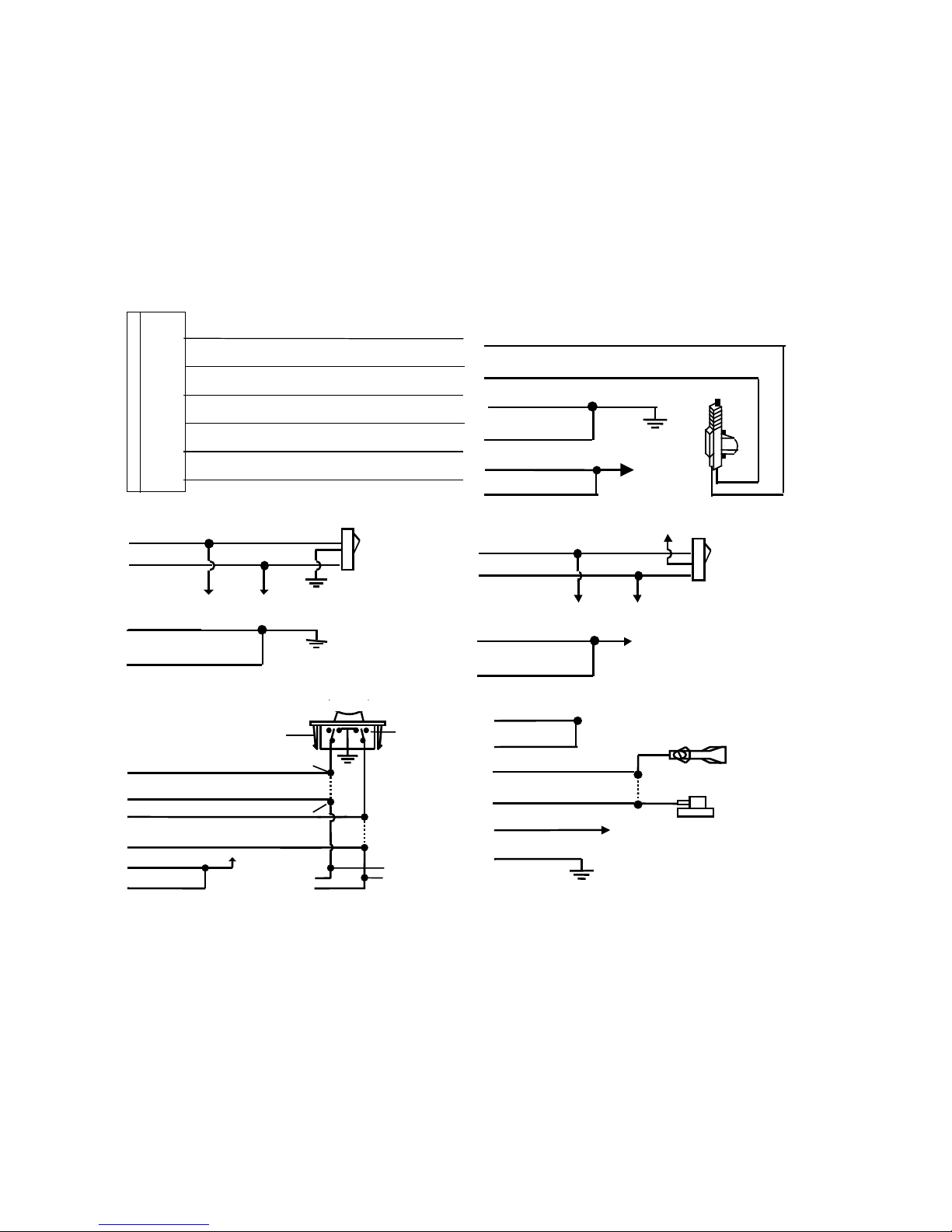
H2. 3-PIN BROWN CONNECTOR FOR OPTIONAL PAGING (KNOCK) SENSOR
An optional Paging (Knock) Sensor can be added on.
1. Detach the protective paper from the double-sided adhesive tape and attach one side of the
double-sided adhesive tape to the bottom part of the Paging (Knock) Sensor.
2. After cleaning the area around the left bottom part of the front windshield so that it stays attached
firmly, the Paging Sensor should be attached on the front window so that the side on which a sticker
with a printed words “Tap Here Paging Driver” is attached face outward.
3. Hide the wire by carefully pushing it inside the space of the front windshield’s mold trim.
Adjust the sensitivity of the Paging Sensor. If you turn the tuning screw at the center of the Paging Sensor
clockwise, the sensitivity goes sharp (higher) and if turned counter-clockwise, the sensitivity goes dull
(lower).
H6. 4 PIN ORANGE CONNECTOR FOR 2 STAGE SHOCK SENSOR
4. Green Wire / Warn Away Input
3. Blue Wire / Zone 4 Ground Trigger
2. Black Wire / Negative
1. Red Wire / +12Volts
H7. BLACK 4-PIN CONNECTOR. – TWO-WAY TRANSCEIVER/ANTENNA MODULE
The Two-way transceiver/antenna mounts on the location above the belt line (dashboard) of the vehicle
for best reception. We suggest you mount it on the lower left or upper left-hand side of the windshield.
Warning! Do not mount in such a manner that it obstructs the driver’s visibility.
- Remove the protective tape backing.
- Carefully align the two-way transceiver/antenna and apply to windshield.
- Route the black connector wire behind the trim and connect to the two-way transceiver/antenna.
- Connect the other end to the control module.
- Special considerations must be made for type of windshield glass, as some newer vehicles utilize a
metallically shielded or infrared and UV radiation absorbing window glass that will inhibit or restrict RF
reception. In these vehicles, route the two ways transceiver/antenna module away from metallic
MEGA 2550 INSTALL 4

shielded window glass as far as possible. There might be an area of the windshield that does not have
protection.
H8. 10-PIN MINI CONNECTOR WIRE HARNESS.
H8/1. Yellow wire – To Ignition Switched +12V –
This wire is connected to a switched 12 volts source. This wire should receive "12 volts" when the ignition
key is in the "ON" and "START" position. When the ignition is turned "OFF", this wire should receive "0"
voltage.
H8/2. Blue / White wire – (-) Instant Trigger or Major trigger Input (Zone 2) –
This wire is the ground trigger input wire for hood/trunk pin switches.
H8/3. Violet wire – Positive Door Switch Sensing Input –
This wire is the positive trigger input wire for positive door pin switch. This wire is the connection for
"positive" type factory door pins (typical of Ford vehicles). Locate the "common wire" for all door pins and
make the connection of the Violet Wire here.
H8/4. Green wire – Negative Door Switch Sensing Input –
This wire is the ground trigger input wire for negative door pin switch. This wire is the connection for
"grounding" type factory door pins. Locate the "common wire" that connects the door pin switches. Make
the connection of the GREEN Wire here.
H8/5. Orange wire – (-) 200mA Grounded Output When Armed –
This wire will become grounded when the alarm is armed. The current capacity of this wire is 200mA. This
output can control the starter disable, when an intrusion is detected and the system is triggered. The
vehicle is prevented from any unauthorized starting.
a). Find the wire from the starter solenoid, (usually located on the starter) and going to the ignition switch.
b). When found, use voltmeter, connect one probe of the voltmeter to ground and connect the other end of
the probe to the starter wire. It should receive "12 volts" only when the ignition key in the "START"
position.
c). After locating the correct wire, cut it in half, try to start the vehicle. The engine should not "crank over".
d). If extended wires are needed, they must be exactly the same gauge as the cut wire. Connect the cut
wire from the key switch to the RED wire (pin #30) of the relay, and connect the starter wire to the
WHITE wire (pin #87a ) of the relay.
e). Connect the ORANGE Wire from the control module to the ORANGE wire (pin #86) of the relay.
f). Connect the ORANGE wire (pin #85) of the relay to a switched 12 volts source from the ignition switch.
NOTE: If more than one electronic device will be connected to the ORANGE Wire, it will be necessary to
isolate the connection of each device control wires with a 1N4003 diode.
87
87a
85
30
86
IN4003 Diode
H8/5: ORANGE wire
from control module
“Start”
“On”
White wire
X
Cut
Red wire
Orange wire
“Acc”
“Off”
Starter
Orange wire to
Ignition Switch
H8/6. Brown / Black wire – (-) 200mA Horn Output –
This wire is provided to use the existing vehicle's horn as the alarm system's optional warning audible
device. It's a transistorized low current output, and should only be connected to the low current ground
output from the vehicle's horn switch. When the system is triggered, the horn will sound.
H8/7. Light Green / Black wire – (-) 200mA 2-Step Door Unlock Output –
The 2-step door unlock feature will work for the most fully electronic door lock circuit. The vehicle must
have an electronic door lock switch (not the lock knob or key switch), which locks and unlocks all of
vehicle's doors. When wired for this feature, pressing the disarm (or unlock) button one time will disarm
the alarm and unlock the driver's door only. If, you press the disarm (or unlock) button two times within 3
seconds, the alarm will disarm and all the doors will unlock.
H8/8 Purple / Black wire – (-) 200mA Channel 4 Programmable Output –
This wire is built-in user-programmable timer output provides a ground through this wire. Press the
transmitter and buttons at the same time. You may program the built-in timer to send a ground
signal for any time interval between 1 second and 2 minutes. For instance, this timer output may be used
to turn on the headlight with the remote control. Also on certain BMW, Mercedes Benz, Jaguar and
Volkswagen cars, you can use this unique timed output to allow remote closure of all power window and
sunroof without the need for an external module!
H8/9. Red / White wire – (-) 200mA Channel 3 (Trunk) Output –
MEGA 2550 INSTALL 5

This will become a 1 second pulse ground by activating channel 3 on the transmitter for two seconds. The
current capacity of this wire is 200mA. This feature allows you to remote control the trunk release or
another electric device. This output can also be programmed to provide the following type of output:
1-second pulse, latched, timer control, and pager. (See Alarm Feature III - 3 Programming
H8/10.Black / White wire – (-) 200mA Dome Light Control Output –
This wire becomes grounded when the dome light control circuit is active. The current capacity of this wire
is 200mA. This wire can control the operation of the interior lights. An optional 10 Amp relay can be used
on this system for interior lights operation.
a). Upon disarming, the interior lights will remain on for 30 seconds.
b). If the vehicle is violated, the interior lights will flash for the same duration as the siren.
H4. 6 PIN DOOR LOCK HARNESS:
Blue/White Wire:(30) - Door Unlock Relay
Blue/Red Wire:(87a) - Door Unlock Relay
Blue/Yellow Wire:(87) - Door Unlock Relay
Green/Red Wire:(87a) - Door Lock Relay
Green/White Wire:(30) - Door Lock Relay
Green/Yellow Wire: (87) - Door Lock Relay
INSTALL NEW DOOR LOCK MOTORS
+12V
Green/ white
Blue/ white
Blue/ red
Green/ red
Green/ yellow
Blue/ yellow
N
EGATIVE TRIGGER DOOR LOCK SYSTEM
Blue / white
Green / white
Door Lock
Maste
r
Locking
Switch
Door unlock
Green / yellow
Blue / yellow
POSITIVE TRIGGER DOOR LOCK SYSTEM
Blue / white
Green / white
Door Loc
k
Master
Locking
Switch
Door unloc
k
Green /
y
ellow
Blue / yellow
+ 12V
+ 12V
ALTERNATING DOOR LOCKS
+12V
Master Door
Lock Switch
X
X
Splic
Splic Cut the
Existing
Lock Wire
To Door
Lock
To Slave Door
Lock switches
Green/ white
Green/ red Cut the Existing
Unlock Wire
Blue/ white
Blue/ red
+ 12V
Green/ yellow
Blue/ yellow
VACUUM OPREATE DOOR LOCKING SYSTEM
Green/ white
Blue/ red
Green/ red
Blue/ white
Blue/ yellow
Green/ yellow +12V
X
Cut
Compressor
Door Switch
MEGA 2550 INSTALL 6

2 STEP DOOR UNLOCK WIRE CONNECTION FOR
5 WIRE ALTERNATING DOOR LOCKS
+12V
Cut the Existing
Lock Wire
Green / White
Blue / Red
Green / Red
Cut Existing Unlock
X
Blue / White
Cut the Unlock Wire
Lock
Unlock
OEM Door Master Lock
OEM Slave
Door Lock
Switch
+12V LockUnlock
To All Other
Door Lock
Motors
LT. Green /
Black Wire
x
X
OEM
Door Lock
Motor
Blue / Yellow
Green / Yellow + 12V
+ 12V
85
86 87
87A
30
H4
6-Pin
Door
Lock
Wire
Harness
VACUUM OPERATED DOOR LOCKING SYSTEM:
TYPICAL OF MERCEDES BENZ AND AUDI.
Locate the wire under the driver's kick panel. Use the
voltmeter connecting to ground, verify that you have t
h
correct wire with the doors unlocked, the voltmeter wil
l
receive "12 volts". Lock the doors and the voltmeter w
i
read "0 volt". Move the alligator clip to +12V and the
voltmeter will receive "12 volts". Cut this wire and mak
connections. Be sure to program door lock timer to
3.5 seconds. (See Feuture II – 1 Programming.)
2 STEP DOOR UNLOCK WIRE CONNECTION FOR
GROUND SWITCHED DOOR LOCKS
Cut Existin
g
Unlock
X
LockUnlock
OEM Door Master Lock Switch
To All Other
Door Lock
Motor
LT. Green / Black
Wire
OEM
Door Lock
Motor
Blue / White
Green / White
Green / Yellow
Existing
Lock Wire
Existing
Unlock Wire
H4
6-Pin
Door
Lock
Wire
Harness
Blue / Red
Blue / Yellow +12V OEM Door
Lock Relay
2 STEP DOOR UNLOCK WIRE CONNECTION FOR
POSITIVE SWITCHED DOOR LOCKS
Cut Existing Unlock
X
LockUnlock
OEM Door Master Lock
To All Other
Door Lock
Motors
LT. Green /
Black Wire
OEM Driver's
Door Lock
Motor
+ 12V
Blue / Red
Existing Pos.
Lock Wire
Existing Pos.
Unlock Wire
30
87A
87
86 85
+12V
Blue / White
Green / White
Green / Yellow
Blue / Yellow + 12V
OEM Door
Lock Relay
H4
6-Pin
Door
Lock
Wire
Harness
PROGRAMMING
A. THE TRANSMITTERS:
Note: This mode will only retain the last 4 remote transmitters programmed. If the transmitter memory is
exceeded, the security system will start deleting transmitters from the memory in chronological order.
1. Turn the Ignition switch ‘OFF/ON’ 3 TIMES and stay in the ON position. Within 15 seconds.
2. Push the Valet switch 3times and holding in on 3rd push until a long chirp is heard. Then release the
valet switch. You are now in the Transmitter programming mode.
3. Press and hold any button of the transmitter until the siren responds with a confirming chirp, indicating
the signal has been stored into memory.
4. If you have additional transmitters (up to 4) that need to be programmed, repeat step 3 for each
transmitter.
Exit: Turn Ignition to 'OFF' position, or leave it for 15 seconds. 3 long chirps & 3 parking light flashes will
confirm transmitter programming exit.
MEGA 2550 INSTALL 7

B. ALARM FEATURES PROGRAMMING:
ALARM FEATURE “I” PRORAMMING:
1. Turn the Ignition switch ‘ON/OFF’ 3 TIMES and stay in the OFF position.
2. Push the Valet switch 2times and hold it on 2nd push until one chirp with a long chirp is heard. Then
release the valet switch. You are now in the Alarm feature ‘I’ programming mode.
3. Press and release the transmitter button ‘A’ corresponding to the feature ‘A’ you want to change.
a. The siren chirps and LED pause will indicate previously setting.
b. The system would advance to [2] LED flash, [2] chirp. (The factory default settings are always [1]
LED flash, [1] chirp.)
4. Depress the transmitter button ‘A’ again to change the feature again. Simple keep re-depressing the
transmitter button ‘A’ again until the module advances to your desired setting.
5. Depress the transmitter button ‘B’ corresponding to the feature ‘B’ you want to program.
Press
Transmitter
Button
One Chirp /
One LED Pulse
Factory Default
Setting
Two Chirps /
Two LED Pulses
Three Chirps /
Three LED Pulses
Four Chirps /
Four LED Pulses
1 All Chirps off All Chirps on Siren Chirps on only Horn Chirps on only
2 Automatic Rearm
off Automatic Rearm on
3 45 seconds Delay
Door Ajar error
chirp.
Instantly Door Ajar
error chirp
4 Without Car-jack
mode Active Car-jack
mode Passive Car-jack
mode
Exit: Turn Ignition to the 'ON' position, or leave it for 15 seconds. 3 long chirps will confirm exit.
ALARM FEATURE “II” PRORAMMING:
1. Turn the Ignition switch ‘ON/OFF’ 3 TIMES and stay in the OFF position.
2. Push the Valet switch 4times and hold it on the 4th push until two chirps with a long chirp is heard.
Then release the valet switch. You are now in the Alarm feature ‘II’ programming mode.
3. Press and release the transmitter button ‘A’ corresponding to the feature ‘A’ you want to program.
Press
Transmitter
Button
One Chirp /
One LED Pulse
Factory Default
Setting
Two Chirps /
Two LED Pulses
Three Chirps /
Three LED Pulses
Four Chirps /
Four LED Pulses
1 0.9-second door
lock pulses. 3.5-second door lock
pulse. Double pulse unlock Door lock with
“Comfort Feature”
2 Active arming Passive arming
without passive door
locking
Passive arming with
passive door locking
3 Ignition controlled
door lock &
unlock
Ignition controlled
door lock only Ignition controlled
door unlock only Without ignition
controlled door lock
& unlock
4 Pathway
illumination
feature “off”
Parking light “on” for
30 seconds upon an
unlock signal
Parking light “on” for
30 seconds upon an
unlock signal & 10
seconds upon a lock
signal.
Exit: Turn Ignition to the 'ON' position, or leave it for 15 seconds. 3 long chirps will confirm exit.
Comfort Feature:
Some Vehicles have a special “COMFORT feature”. When you lock the door with the key, you just have to
keep on turning the key on the door about 5 or 7 seconds and the window will close directly.
If your vehicle with “COMFORT feature” and you wish the door being locked and the window being closed
automatically at the same time by remote control, you can set the alarm feature II-1 “with comfort feature”.
MEGA 2550 INSTALL 8

ALARM FEATURE “III” PRORAMMING:
1. Turn the Ignition switch ‘ON/OFF’ 3 TIMES and stay in the OFF position.
2. Push the Valet switch 6times and hold it on the 6th push until three chirps with a long chirp is heard.
Then release the valet switch. You are now in the Alarm feature ‘III’ programming mode.
3. Press and release the transmitter button ‘A’ corresponding to the feature ‘A’ you want to program.
Press
Transmitter
Button
One Chirp /
LED one pulse
Factory Default
Setting
Two Chirps /
LED two pulses
Three Chirps /
LED three pulses
Four Chirps /
LED four pulses
The vehicle has an aftermarket Turbo timer installed: The system
can be armed with the engine running and:
1 Vehicles without
Turbo (The system
cannot be armed
with the engine
running)
The shock sensor
will be bypassed as
long as the engine
running.
The shock sensor
will be bypassed for
one minute
The shock sensor
will be bypassed for
three minutes
2 H1/4 Brown Wire =
Constant siren
output for six-tone
siren
H1/4 Brown Wire =
5-second pulse siren
output for single-tone
siren
H1/4 Brown Wire =
Random pulse siren
output
H1/4 Brown Wire =
Pulse output
3 H7/7 Red / White
Wire Channel 3 =
1 second pulse
output for trunk
release.
H7/7 Red / White
Wire Channel 3 =
Latch output
H7/7 Red / White
Wire Channel 3 =
Timer controlled
output
4 H7/10 Purple /
Black Wire Channel
4 =
Momentary output
H7/10 Purple / Black
Wire Channel 4 =
Latched output
H7/10 Purple / Black
Wire Channel 4 =
Latched output and
reset with ignition
“ON”
H7/10 Purple / Black
Wire Channel 4 =
Timer programming
(set to any interval
between 1 second
and 2 minutes.)
Exit: Turn Ignition to the 'ON' position, or leave it for 15 seconds. 3 long chirps will confirm exit.
Channel 3 (4) Timer Control Output Programming
1. Turn the Ignition switch ‘ON/OFF’ 3 TIMES and stay in the OFF position.
2. Push the Valet switch 6times and hold it on the 6th push until three chirps with a long chirp is heard.
Then release the valet switch. You are now in the Alarm feature ‘III” programming mode.
3-a. Press and release the transmitter button 3 times, [3] LED flash, [3] siren/horn chirp to indicate
you are in features “Channel 3 Timer Programming mode”.
3-b. Press and release the transmitter button 4 times, [4] LED flash, [4] siren/horn chirp to indicate
you are in features “Channel 4 Timer Programming mode”.
4. Press and hold the valet switch, the timer will immediately start.
5. When the desired interval has passed, release the valet switch. 1 long chirp for confirmation.
(Set to any interval between 1 second and 2 minutes)
Note 1: If your built-in timer controls window/sunroof closure in your car, DO NOT change the timer
setting! This requires installer-only programming. Changing the value will adversely effect
operation and may cause damage.
Note 2:
Momentary output: The momentary output selection will output a negative signal from the Channel 4
output immediately when the Channel 4 button is pressed and will continue until the button is released.
Latched output: The latched output selection will output a negative signal as soon as the Channel 3 (4)
button is pressed and will continue until the button is pressed again.
Latched output / reset with ignition: The latched / reset with ignition output selection operates just like
the latched output but will reset or stop when the ignition is turned on.
MEGA 2550 INSTALL 9

ALARM FEATURE “IV” PRORAMMING:
1. Turn the Ignition switch ‘ON/OFF’ 3 TIMES and stay in the OFF position.
2. Push the Valet switch 8times and hold it on the 8th push until four chirps with a long chirp is heard.
Then release the valet switch. You are now in the Alarm feature ‘IV’ programming mode.
3. Press and release the transmitter button ‘A’ corresponding to the feature ‘A’ you want to program.
Press
Transmitter
Button
One Chirp /
LED one pulse
Factory Default Setting
Two Chirps /
LED two pulses
1 Exit the programming mode. (3 long chirps to confirm this exit.)
2 Override Without Password Pin Code /
Press & hold button for 4 seconds to
delete the Password pin code
Override With Password Pin Code /
Password pin code programming
3 “TEST” Mode for Zone 2 Hood & Zone 3
Door Pin Switch “TEST” Mode for Zone 4 / the Optional
Sensor connected to 4-pin plug.
Exit: Turn Ignition to the 'ON' position, or leave it for 15 seconds. 3 long chirps will confirm exit.
Password Pin Code Setup:
1. Turn the Ignition 'switch ‘ON/OFF’ 3 times and stay in OFF position.
2. Push the Valet switch 8times and hold it on the 8th push until four chirps with a long chirp is heard.
Then release the valet switch. You are now in the Alarm feature ‘IV’ programming mode.
3. Press and release the transmitter button once, [2] LED flash, [2] siren/horn chirp to indicate you are
in features “Password Pin Code Programming mode”.
4. Within 15 seconds, begin to enter your chosen first 9ths digit by pressing and releasing the valet switch
from 1 – 9 times.
5. Within 15 seconds of the last entered 10ths digit, turn the Ignition switch to the “ON” position.
6. Within 15 seconds, enter your chosen second 10ths digit by pressing and releasing the valet switch
from 1 – 9 times.
7. Finish by turning the ignition switch to the “OFF” position.
If the new password code were accepted, the unit would report the newly entered code, by flashing the
LED, first indicating the first digit code has been memorized, pause, and then the second digit code. The
unit will report the new code three times with a one-second pause between each code.
Note: If 15 seconds of inactivity expire, or if the ignition switch is turned “ON” for more than 5 seconds
during of the above steps, the unit will go back to the last successfully stored code. [3] long chirps will
confirm password programming exit.
Delete Password Pin Code (Override Without Password Pin Code):
(Factory default setting)
1. Turn the Ignition switch ‘ON/OFF’ 3 times and stay in the OFF position.
2. Push the Valet switch 8times and hold it on the 8th push until four chirps with a long chirp is heard.
Then release the valet switch.
3. Within 15 seconds, press and hold the transmitter button for 4 seconds. One long chirp to confirm
that the Password Pin Code has been deleted.
Example: To program the Password Code 92, you would:
1. Turn the Ignition switch ‘ON/OFF’ 3 times and stay in the OFF position.
2. Push the Valet switch 8times and hold it on the 8th push until four chirps with a long chirp is heard.
Then release the valet switch. You are now in the Alarm feature ‘IV’ programming mode.
3. Press and release the transmitter button once, [2] LED flash, [2] siren/horn chirp to indicate you are
in feature “Password pin code programming mode”.
4. Within 15 seconds, press and release the valet switch 9 times.
5. Within 15 seconds of the last entered 10ths digit, turn the Ignition Switch to “ON” position.
6. Within 15 seconds press and release the valet switch 2 times.
7. Turn the Ignition Switch to the “OFF’ position.
You will note the LED flashing nine times, pause and then flash two times, pause. This pattern will be
repeated three times indicating the new code (92) has been accepted and stored in the memory.
MEGA 2550 INSTALL 10

Test Mode
In this test mode, this system can test the Zone 1 Warn Away Trigger / Zone 2 Instant ground trigger /
Zone 3 Door trigger and the Zone 4 optional sensor sensitivity. The installer can save time to test the
optional sensor sensitivity and sensor without using the traditional arming/disarming procedures to test the
sensors.
Enter:
1. Turn the Ignition switch ‘ON/OFF’ 3 TIMES and stay in the OFF position.
2. Push the Valet switch 8times and hold it on the 8th push until four chirps with a long chirp is heard.
Then release the valet switch. You are now in the Alarm feature ‘IV’ programming mode.
3-a. Test the Zone 2 Instant Ground Trigger & Zone 3 Door Trigger:
Press and release the transmitter button once. [1] LED flash, [1] siren/horn chirp to indicate you
are in Zone 2 / instant ground trigger and Zone 3 / Door trigger test mode.
Trigger sensor Siren chirps
Zone 2 / Instant Ground trigger (H7/2 Blue/White wire) 2
Zone 3 / Door trigger (H7/3 Violet & H7/5 Green Wire) 3
3-b. Test the Zone 1 / 2 Shock Sensor (Connected to H2 4 Pin Plug):
Press and release the transmitter button again. [2] LED flash, [2] siren/horn chirps to indicate you
are in shock sensor (connected to H2 4 pin plug) test mode.
1. Activate the warn-away (first stage optional sensor). The system will emit a short chirp.
2. Activate the full alarm (second stage optional sensor). The system will emit a long chirp.
3. Continue to test the optional sensor until you reach the proper sensitivity.
Return To Factory Default Setting:
1. Turn the ignition ON then OFF 3 TIMES and stay in the OFF position.
2. Push the Valet switch 12 times and hold it on the 12th push until six chirps with a long chirp is heard.
Then release the valet switch. You are now in the “Return to Factory Default Setting” programming
mode.
3. Press the and buttons at the same time on the transmitter together for 5 seconds, there will be
a confirmation six chirp with 3 long chirp to confirm the system Alarm Feature I & II & III & IV
Programming all returns to factory default setting.
This device complies with part 15 of the FCC rules. Operation is subject to the following two conditions.
(1) This device may not cause harmful interference, and
(2) This device must accept any interference received, including interference that may cause undesired
operation.
MEGA 2550 INSTALL 11

MEGA 2550 INSTALL 12
Table of contents
Other Megalarm Car Alarm manuals

Megalarm
Megalarm MEGA 3700 User manual

Megalarm
Megalarm MEGA 3600 User manual

Megalarm
Megalarm MEGA 474 User manual

Megalarm
Megalarm 520 User manual

Megalarm
Megalarm MEGA 450 Installation instructions

Megalarm
Megalarm MEGA 3700 User manual

Megalarm
Megalarm MEGA 2700 User manual

Megalarm
Megalarm MEGA500C User manual
Popular Car Alarm manuals by other brands

Audiovox
Audiovox Prestige APS-25HJ owner's manual

Mercura
Mercura SIREN FLASH MODULE Technical Description & Cabling

CrimeStopper
CrimeStopper CS-2015.FM.RevB installation instructions

CrimeStopper
CrimeStopper CM-2500 user manual

Fortin
Fortin FSA-206L FSA-208 user guide

CompuSTARPro
CompuSTARPro CM4000 installation manual