MegaSquirt MS3-PRO User manual


CONTENTS CONTENTS
Contents
1 Introduction 11
1.1 Overview ............................................ 11
1.1.1 Warninglabels ..................................... 11
1.1.2 Technicalsupport ................................... 12
1.1.3 Copyrights ....................................... 12
1.2 MS3-Procomponents ..................................... 12
1.2.1 MS3-Pro Engine Control Unit . . . . . . . . . . . . . . . . . . . . . . . . . . . . . 12
1.2.2 Wiringharness..................................... 12
1.2.3 Tuningcables...................................... 12
1.3 MS3-Proaccessories ..................................... 13
1.3.1 Sensors......................................... 13
1.3.2 QuadSpark ....................................... 13
1.3.3 Ignitioncoils ...................................... 13
1.3.4 CAN-EGT thermocouple interface . . . . . . . . . . . . . . . . . . . . . . . . . . 13
1.3.5 MicroSquirt....................................... 13
1.3.6 Partnumbers...................................... 14
1.4 Tools............................................... 14
2 Installing software 15
2.1 TunerStudio........................................... 15
2.1.1 Startscreen....................................... 15
2.1.2 Creatingaproject ................................... 16
2.1.3 TunerStudio main screen . . . . . . . . . . . . . . . . . . . . . . . . . . . . . . . 19
3 MS3-Pro hardware 21
3.1 Overview ............................................ 21
3.2 Inputs .............................................. 23
3.2.1 Enginespeed...................................... 23
3.2.2 Temperatureinputs................................... 23
3.2.3 Throttleposition .................................... 23
3.2.4 O2sensorinput .................................... 23
3.2.5 MAPsensorinput ................................... 23
3.2.6 General purpose analog inputs . . . . . . . . . . . . . . . . . . . . . . . . . . . . 23
3.2.7 Knockinput....................................... 24
3.2.8 DigitalI/Ochannels .................................. 24
3.3 Outputs ............................................. 24
3.3.1 Injectoroutputs..................................... 24
3.3.2 Ignitionoutputs..................................... 24
3.3.3 Highcurrentoutputs.................................. 24
3.3.4 PWM medium current outputs . . . . . . . . . . . . . . . . . . . . . . . . . . . . . 25
3.3.5 Tachoutput....................................... 25
3.3.6 Stepper motor control output . . . . . . . . . . . . . . . . . . . . . . . . . . . . . 25
3.4 Communicationslines ..................................... 25
3.4.1 RS232.......................................... 25
3.4.2 USB........................................... 25
3.4.3 CANbus......................................... 25
3.5 Maintenance inside the case . . . . . . . . . . . . . . . . . . . . . . . . . . . . . . . . . 26
3.5.1 Changingthefuses .................................. 26
3.5.2 ReplacingtheSDcard................................. 26
3.5.3 Changing the real time clock battery . . . . . . . . . . . . . . . . . . . . . . . . . 26
DIYAutoTune.com MS3-Pro manual version 1.036, firmware 1.3.4, 6/10/2015 Page 2

CONTENTS CONTENTS
3.5.4 Improving the waterproofing . . . . . . . . . . . . . . . . . . . . . . . . . . . . . . 27
4 Wiring 28
4.1 ECUpinout ........................................... 28
4.2 Wiringdiagram ......................................... 31
4.3 Enginepositionsensors.................................... 35
4.3.0.1 Variable reluctor sensors . . . . . . . . . . . . . . . . . . . . . . . . . . 35
4.3.0.2 Hall effect and optical sensors . . . . . . . . . . . . . . . . . . . . . . . 35
4.3.0.3 Points triggering and points replacement devices . . . . . . . . . . . . . 36
4.3.0.4 Fuel only with an MSD box or similar . . . . . . . . . . . . . . . . . . . 36
4.4 Othersensors.......................................... 36
4.4.1 Temperaturesensors ................................. 36
4.4.2 MAPsensors...................................... 37
4.4.3 Throttle position sensor . . . . . . . . . . . . . . . . . . . . . . . . . . . . . . . . 37
4.4.4 Massairflowsensors ................................. 38
4.4.4.1 Ford 5.0 Mustang 4 pin oval connector MAF . . . . . . . . . . . . . . . 39
4.4.4.2 Ford 5 pin rectangular connector MAF . . . . . . . . . . . . . . . . . . . 39
4.4.4.3 Nissan / Infiniti Q45 MAF . . . . . . . . . . . . . . . . . . . . . . . . . . 39
4.4.5 Oxygensensors .................................... 40
4.4.6 Knocksensors ..................................... 41
4.4.7 Speedandgearsensors ............................... 41
4.4.8 Generic on/off switches . . . . . . . . . . . . . . . . . . . . . . . . . . . . . . . . 41
4.4.9 Othersensors ..................................... 42
4.5 Fuelinjectors .......................................... 42
4.6 Ignitionoutputs......................................... 42
4.6.0.1 QuadSpark ignition module . . . . . . . . . . . . . . . . . . . . . . . . . 42
4.6.0.2 IGN-1A coil with built in ignition module . . . . . . . . . . . . . . . . . . 43
4.6.0.3 LSseriescoils................................ 43
4.6.0.4 VWpencilcoils................................ 43
4.6.0.5 MSD and other single channel capacitive discharge ignitions . . . . . . 44
4.6.0.6 Common firing orders . . . . . . . . . . . . . . . . . . . . . . . . . . . . 45
4.7 IACvalves............................................ 46
4.7.1 StepperIACvalves................................... 46
4.7.2 PWMIACvalves.................................... 48
4.7.3 On/offIACvalves.................................... 49
4.7.4 ThermalIACvalves .................................. 49
4.7.5 DC servo IAC valves (currently not supported) . . . . . . . . . . . . . . . . . . . 49
4.8 Fuelpumprelay ........................................ 49
4.9 Tachoutput ........................................... 49
4.10Highcurrentoutputs ...................................... 49
4.11 PWM medium current outputs . . . . . . . . . . . . . . . . . . . . . . . . . . . . . . . . . 49
4.12Groundingnotes ........................................ 50
5 Setting up a basic configuration 51
5.1 Connecting the MS3-Pro to your laptop . . . . . . . . . . . . . . . . . . . . . . . . . . . 51
5.2 Basicengineconstants .................................... 52
5.3 Ignitionsettings......................................... 55
5.3.1 Specific ignitions: Basic Trigger . . . . . . . . . . . . . . . . . . . . . . . . . . . . 60
5.3.1.1 Inputphasing................................. 60
5.3.1.2 Ford TFI distributors . . . . . . . . . . . . . . . . . . . . . . . . . . . . . 61
5.3.1.3 GMHEI.................................... 62
5.3.2 Specific ignitions: Trigger Return . . . . . . . . . . . . . . . . . . . . . . . . . . . 62
DIYAutoTune.com MS3-Pro manual version 1.036, firmware 1.3.4, 6/10/2015 Page 3

CONTENTS CONTENTS
5.3.3 Specific (non) ignition: Fuel only . . . . . . . . . . . . . . . . . . . . . . . . . . . 62
5.3.4 Specific ignition: Toothed wheel . . . . . . . . . . . . . . . . . . . . . . . . . . . 63
5.3.4.1 Terminologynotes.............................. 64
5.3.4.2 Wheelnaming ................................ 65
5.3.4.3 Specificsettings ............................... 65
5.3.4.4 Existing.................................... 66
5.3.4.5 Retrofit .................................... 66
5.3.4.6 Missing tooth crank wheel . . . . . . . . . . . . . . . . . . . . . . . . . 67
A note about VR sensors and missing tooth wheels . . . . . . . . . . . . . 68
5.3.4.7 Missing tooth cam wheel . . . . . . . . . . . . . . . . . . . . . . . . . . 68
5.3.4.8 Missing tooth crank wheel and single tooth cam wheel . . . . . . . . . . 69
5.3.4.9 Missing tooth crank wheel and polled (50/50 or half moon) cam wheel . 71
5.3.4.10NipponDensoCAS ............................. 75
5.3.4.11 Non-missing tooth cam wheel with single-tooth cam . . . . . . . . . . . 76
5.3.4.12 Non-missing tooth cam wheel with two opposite teeth on the cam . . . 79
5.3.4.13 Non-missing tooth cam wheel with one cam tooth per cylinder . . . . . 79
5.3.4.14 Non-missing tooth crank wheel with one cam tooth . . . . . . . . . . . . 80
5.3.4.15 Other wheel arrangements . . . . . . . . . . . . . . . . . . . . . . . . . 83
5.3.5 Specific ignitions: EDIS and EDIS Multispark . . . . . . . . . . . . . . . . . . . . 83
5.3.5.1 Checking the timing . . . . . . . . . . . . . . . . . . . . . . . . . . . . . 84
5.3.5.2 Cam sensor and EDIS . . . . . . . . . . . . . . . . . . . . . . . . . . . 85
5.3.6 Specific ignitions: 420A/Neon . . . . . . . . . . . . . . . . . . . . . . . . . . . . . 85
5.3.7 Specific ignitions: 36-2+2 . . . . . . . . . . . . . . . . . . . . . . . . . . . . . . . 85
5.3.8 Specific ignitions: 36-2-2-2 . . . . . . . . . . . . . . . . . . . . . . . . . . . . . . 86
5.3.9 Specific ignitions: Subaru 6/7 . . . . . . . . . . . . . . . . . . . . . . . . . . . . . 86
5.3.10 Specific ignitions: Miata 99-05 . . . . . . . . . . . . . . . . . . . . . . . . . . . . 86
5.3.11 Specific ignitions: 6G72 . . . . . . . . . . . . . . . . . . . . . . . . . . . . . . . . 86
5.3.12 Specific ignitions: IAW Weber . . . . . . . . . . . . . . . . . . . . . . . . . . . . . 87
5.3.13 Specific ignitions: CAS 4/1 . . . . . . . . . . . . . . . . . . . . . . . . . . . . . . 87
5.3.14 Specific ignitions: 4G63 . . . . . . . . . . . . . . . . . . . . . . . . . . . . . . . . 87
5.3.15 Specific ignitions: Twin trigger . . . . . . . . . . . . . . . . . . . . . . . . . . . . . 87
5.3.16 Specific ignitions: Chrysler 2.2 / 2.5 . . . . . . . . . . . . . . . . . . . . . . . . . 88
5.3.17 Specific ignitions: Renix 44-2-2 . . . . . . . . . . . . . . . . . . . . . . . . . . . . 88
5.3.18 Specific ignitions: Suzuki Swift . . . . . . . . . . . . . . . . . . . . . . . . . . . . 88
5.3.19 Specific ignitions: Suzuki Vitara 2.0 . . . . . . . . . . . . . . . . . . . . . . . . . 89
5.3.20 Specific ignitions: Daihatsu 3cyl . . . . . . . . . . . . . . . . . . . . . . . . . . . 89
5.3.21 Specific ignitions: Daihatsu 4cyl . . . . . . . . . . . . . . . . . . . . . . . . . . . 89
5.3.22 Specific ignitions: VTR1000 . . . . . . . . . . . . . . . . . . . . . . . . . . . . . . 89
5.3.23 Specific ignitions: Rover #1 . . . . . . . . . . . . . . . . . . . . . . . . . . . . . . 89
5.3.24 Specific ignitions: Rover #2 . . . . . . . . . . . . . . . . . . . . . . . . . . . . . . 89
5.3.25 Specific ignitions: Rover #3 . . . . . . . . . . . . . . . . . . . . . . . . . . . . . . 89
5.3.26 Specific ignitions: GM 7X . . . . . . . . . . . . . . . . . . . . . . . . . . . . . . . 89
5.3.27 Specific ignitions: QR25DE . . . . . . . . . . . . . . . . . . . . . . . . . . . . . . 89
5.3.28 Specific ignitions: Honda RC51 . . . . . . . . . . . . . . . . . . . . . . . . . . . . 90
5.3.29 Specific ignitions: Fiat 1.8 16V . . . . . . . . . . . . . . . . . . . . . . . . . . . . 90
5.3.30 Specific ignitions: Optispark . . . . . . . . . . . . . . . . . . . . . . . . . . . . . . 90
5.3.31 Specific ignitions: Nissan SR20 . . . . . . . . . . . . . . . . . . . . . . . . . . . . 91
5.3.32 Specific ignitions: Nissan RB25 . . . . . . . . . . . . . . . . . . . . . . . . . . . . 91
5.3.33Specificignitions:LS1................................. 91
5.3.34 Specific ignitions: YZF1000 . . . . . . . . . . . . . . . . . . . . . . . . . . . . . . 92
5.3.35 Specific ignitions: Honda Acura (V6) . . . . . . . . . . . . . . . . . . . . . . . . . 92
5.3.36 Specific ignitions: VQ35DE . . . . . . . . . . . . . . . . . . . . . . . . . . . . . . 92
DIYAutoTune.com MS3-Pro manual version 1.036, firmware 1.3.4, 6/10/2015 Page 4

CONTENTS CONTENTS
5.3.37 Specific ignitions: Jeep 2000 . . . . . . . . . . . . . . . . . . . . . . . . . . . . . 92
5.3.38 Specific ignitions: Jeep 2002 . . . . . . . . . . . . . . . . . . . . . . . . . . . . . 93
5.3.39 Specific ignitions: Zetec VTC . . . . . . . . . . . . . . . . . . . . . . . . . . . . . 93
5.3.40 Specific ignitions: Flywheel tri-tach . . . . . . . . . . . . . . . . . . . . . . . . . . 93
5.3.41 Specific ignitions: 2JZ VVTi . . . . . . . . . . . . . . . . . . . . . . . . . . . . . . 94
5.3.42 Specific ignitions: Honda TSX / D17 . . . . . . . . . . . . . . . . . . . . . . . . . 94
5.3.43 Specific ignitions: Viper V10 . . . . . . . . . . . . . . . . . . . . . . . . . . . . . 94
5.3.44 Specific ignition: Honda K24A2 . . . . . . . . . . . . . . . . . . . . . . . . . . . . 94
5.3.45 Specific ignition: HD32-2 . . . . . . . . . . . . . . . . . . . . . . . . . . . . . . . 94
5.3.46 Specific ignition: Miata 36-2 . . . . . . . . . . . . . . . . . . . . . . . . . . . . . . 94
5.4 Idlevalves............................................ 94
5.4.1 On/Offsettings .................................... 95
5.4.2 Steppervalvesettings................................. 95
5.4.3 PWMidlevalvesettings................................ 96
5.5 Sensorcalibration ....................................... 97
6 Tuning the MS3-Pro 99
6.1 Gettingstarted ......................................... 99
6.1.1 Usingoutputtestmode ................................ 99
6.1.1.1 Injectortestmode .............................. 99
6.1.1.2 Coiltestmode ................................100
6.1.1.3 Idlevalvetesting...............................100
Testing a stepper IAC valve . . . . . . . . . . . . . . . . . . . . . . . . . . 101
TestingaPWMIACvalve ...........................102
6.1.2 CheckingRPM.....................................102
6.1.3 Setting cranking timing . . . . . . . . . . . . . . . . . . . . . . . . . . . . . . . . . 103
6.1.4 Startingtheengine...................................103
6.1.5 Settingrunningtiming .................................104
6.2 The basics of 3D tuning tables and load types . . . . . . . . . . . . . . . . . . . . . . . . 105
6.3 Tuningfuel ...........................................107
6.3.1 Deadtime........................................108
6.3.1.1 Injectorsettings ...............................108
6.3.2 Smallpulsewidths...................................109
6.3.3 AFRtable........................................110
6.3.4 VEtable.........................................111
6.3.5 Basic acceleration enrichment (AE) tuning . . . . . . . . . . . . . . . . . . . . . . 112
6.3.5.1 Main accel enrich settings menu . . . . . . . . . . . . . . . . . . . . . . 112
6.3.5.2 Accelerator pump AE . . . . . . . . . . . . . . . . . . . . . . . . . . . . 113
6.3.5.3 TimeBasedAE ...............................114
6.3.5.4 Getting it dialed in . . . . . . . . . . . . . . . . . . . . . . . . . . . . . . 117
MAP based or TPS based AE? . . . . . . . . . . . . . . . . . . . . . . . . 117
Setting the TPSdot/MAPdot Threshold Levels . . . . . . . . . . . . . . . . 117
Tuningthetables ................................118
6.3.6 Startup / warmup fueling . . . . . . . . . . . . . . . . . . . . . . . . . . . . . . . . 118
6.3.6.1 Cranking / Startup settings . . . . . . . . . . . . . . . . . . . . . . . . . 119
6.3.6.2 Primingpulse ................................120
6.3.6.3 Afterstart (ASE) percentage . . . . . . . . . . . . . . . . . . . . . . . . 120
6.3.6.4 Afterstart (ASE) taper . . . . . . . . . . . . . . . . . . . . . . . . . . . . 120
6.3.6.5 Warmup enrichment . . . . . . . . . . . . . . . . . . . . . . . . . . . . . 120
6.3.6.6 Putting it all together . . . . . . . . . . . . . . . . . . . . . . . . . . . . . 120
6.4 Tuningspark ..........................................120
6.5 Gettingagoodidle.......................................121
DIYAutoTune.com MS3-Pro manual version 1.036, firmware 1.3.4, 6/10/2015 Page 5

CONTENTS CONTENTS
6.5.0.7 CorrectFuel .................................122
6.5.0.8 CorrectTiming................................122
6.5.0.9 CorrectAirflow................................123
7 Additional items: Beyond basic fuel and ignition control 124
7.1 Basic/LoadSections .....................................124
7.1.1 GeneralSettings....................................124
7.1.1.1 Barometric settings . . . . . . . . . . . . . . . . . . . . . . . . . . . . . 124
7.1.1.2 MAP sensor settings . . . . . . . . . . . . . . . . . . . . . . . . . . . . 125
7.1.1.3 General Sensor Settings . . . . . . . . . . . . . . . . . . . . . . . . . . 125
7.1.1.4 LoadParameters ..............................126
7.1.2 RevLimiter .......................................126
7.1.2.1 Hardrevlimit.................................127
7.1.2.2 Coolant temp limiter . . . . . . . . . . . . . . . . . . . . . . . . . . . . . 127
7.1.2.3 Sparkretard .................................127
7.1.2.4 Sparkcut...................................128
7.1.2.5 Fuelcut....................................128
7.1.3 Shiftlight ........................................128
7.1.4 TachoOutput......................................129
7.1.5 Fancontrol .......................................129
7.1.6 Torque converter lockup . . . . . . . . . . . . . . . . . . . . . . . . . . . . . . . . 131
7.1.7 Barometriccorrection .................................132
7.1.8 MAPsamplesettings .................................132
7.1.8.1 EventAverage................................133
7.1.8.2 TimedMinimum ...............................133
7.1.9 ITBloadsettings....................................135
7.1.9.1 ITBloadVEtable ..............................135
7.1.9.2 ITB load TPS switch point curve . . . . . . . . . . . . . . . . . . . . . . 136
7.1.9.3 ITB Load at TPS Switchpoint Curve . . . . . . . . . . . . . . . . . . . . 136
7.1.9.4 Putting it all Together - Calculating ITB Load . . . . . . . . . . . . . . . 136
7.1.9.5 ITB Load Calculation in Speed-Density Mode . . . . . . . . . . . . . . . 136
7.1.9.6 ITB Load Calculation in Alpha-N Mode . . . . . . . . . . . . . . . . . . 137
7.1.9.7 Tuning For Idle Air Control . . . . . . . . . . . . . . . . . . . . . . . . . 138
7.1.10MAFoptions ......................................138
7.1.10.1 More about frequency based MAFs . . . . . . . . . . . . . . . . . . . . 140
7.1.11MAFflowcurve.....................................141
7.1.11.1MAFLoad ..................................141
7.1.11.2Tuning ....................................141
7.1.11.3 Using VE1 as a trim table . . . . . . . . . . . . . . . . . . . . . . . . . . 142
7.1.12 MAF correction table (old) . . . . . . . . . . . . . . . . . . . . . . . . . . . . . . . 142
7.1.13 MAF / MAT correction table . . . . . . . . . . . . . . . . . . . . . . . . . . . . . . 142
7.1.14RealtimeDisplay....................................143
7.1.15 Feature List Shiwing I/O Pins . . . . . . . . . . . . . . . . . . . . . . . . . . . . . 144
7.1.16 I/O Pins Showing Useage . . . . . . . . . . . . . . . . . . . . . . . . . . . . . . . 144
7.1.17 Expansion I/O Pins List / Usage . . . . . . . . . . . . . . . . . . . . . . . . . . . 144
7.1.18 Gauge and setting limits . . . . . . . . . . . . . . . . . . . . . . . . . . . . . . . . 144
7.2 FuelSettings ..........................................145
7.2.1 Injectortimingtable ..................................145
7.2.2 Secondary injector timing table . . . . . . . . . . . . . . . . . . . . . . . . . . . . 146
7.2.3 Stagedinjection ....................................146
7.2.3.1 Tuning Staged Injection . . . . . . . . . . . . . . . . . . . . . . . . . . . 149
7.2.3.2 Tuning Table-based Staged Injection . . . . . . . . . . . . . . . . . . . . 149
DIYAutoTune.com MS3-Pro manual version 1.036, firmware 1.3.4, 6/10/2015 Page 6

CONTENTS CONTENTS
7.2.3.3 Tuning All other Staged Injection Modes . . . . . . . . . . . . . . . . . . 150
7.2.4 Fuel sensor settings (Flex) . . . . . . . . . . . . . . . . . . . . . . . . . . . . . . 150
7.2.5 AFR/EGOcontrol...................................151
7.2.5.1 Basic EGO settings . . . . . . . . . . . . . . . . . . . . . . . . . . . . . 151
7.2.5.2 EGOports ..................................152
7.2.5.3 AFR/EGO Sensor Mapping . . . . . . . . . . . . . . . . . . . . . . . . . 152
7.2.5.4 Tuning ....................................152
Simple algorithm with narrowband sensor . . . . . . . . . . . . . . . . . . 153
Simple Algorithm with Wideband Sensor . . . . . . . . . . . . . . . . . . . 153
PID Algorithm with Narrowband Sensor . . . . . . . . . . . . . . . . . . . 153
PID Algorithm with Wideband Sensor . . . . . . . . . . . . . . . . . . . . 153
7.2.6 Narrowband EGO targets . . . . . . . . . . . . . . . . . . . . . . . . . . . . . . . 154
7.2.7 AFRsafetysystem...................................154
7.2.8 Cylindertrimtables...................................155
7.2.9 SequencedBatchFire.................................156
7.3 IgnitionSettings ........................................156
7.3.1 Dwell battery correction . . . . . . . . . . . . . . . . . . . . . . . . . . . . . . . . 156
7.3.2 DwellvsRPM......................................156
7.3.3 DwellTable .......................................156
7.3.4 Coldadvance......................................157
7.3.5 MAT based timing retard . . . . . . . . . . . . . . . . . . . . . . . . . . . . . . . . 157
7.3.6 Noisefiltering......................................157
7.3.6.1 Examples...................................160
7.3.7 Knocksensorsettings.................................161
7.3.7.1 Knock sensor settings . . . . . . . . . . . . . . . . . . . . . . . . . . . . 163
7.3.7.2 Detection...................................164
7.3.7.3 Retarding...................................164
7.3.7.4 Recovery...................................164
7.3.7.5 Knock input threshold . . . . . . . . . . . . . . . . . . . . . . . . . . . . 164
7.3.8 Knock sensor parameters . . . . . . . . . . . . . . . . . . . . . . . . . . . . . . . 164
7.3.9 Knockwindowsettings.................................165
7.3.10Knockcoolantscaling .................................166
7.3.11Rotarysettings.....................................166
7.3.11.1FCmode...................................167
7.3.11.2FDmode...................................167
7.3.11.3RX8mode ..................................168
7.3.11.43rotor.....................................168
7.3.11.54rotor.....................................169
7.3.12Rotarysplittable....................................169
7.3.13Cylindertrimtables...................................170
7.4 Startup/Idle ..........................................170
7.4.1 Cranking / startup settings . . . . . . . . . . . . . . . . . . . . . . . . . . . . . . . 171
7.4.2 CrankingTaperCurve .................................172
7.4.3 Priming Pulse 2 through Warmup Enrichment 2 . . . . . . . . . . . . . . . . . . . 172
7.4.4 Idlecontrol .......................................172
7.4.4.1 On/OffValve .................................173
7.4.4.2 Stepper valve settings . . . . . . . . . . . . . . . . . . . . . . . . . . . . 173
7.4.4.3 PWM idle valve settings . . . . . . . . . . . . . . . . . . . . . . . . . . . 174
7.4.5 Idle Cranking Duty / Steps . . . . . . . . . . . . . . . . . . . . . . . . . . . . . . . 175
7.4.6 Idle Warmup Duty / Steps . . . . . . . . . . . . . . . . . . . . . . . . . . . . . . . 175
7.4.7 Closed loop idle settings . . . . . . . . . . . . . . . . . . . . . . . . . . . . . . . . 175
7.4.7.1 Tuning closed loop idle . . . . . . . . . . . . . . . . . . . . . . . . . . . 178
DIYAutoTune.com MS3-Pro manual version 1.036, firmware 1.3.4, 6/10/2015 Page 7

CONTENTS CONTENTS
7.4.8 Closed loop idle target curve . . . . . . . . . . . . . . . . . . . . . . . . . . . . . 181
7.4.9 Closed loop idle initial values . . . . . . . . . . . . . . . . . . . . . . . . . . . . . 181
7.4.10 PWM Idle voltage compensation . . . . . . . . . . . . . . . . . . . . . . . . . . . 182
7.4.11 Air conditioning idle up . . . . . . . . . . . . . . . . . . . . . . . . . . . . . . . . . 182
7.4.12Idleadvancesettings .................................183
7.4.12.1 Idle advance tuning . . . . . . . . . . . . . . . . . . . . . . . . . . . . . 184
7.4.12.2 Tuning Idle Advance Engagement Settings . . . . . . . . . . . . . . . . 184
7.4.12.3 Tuning Idle Advance Timing . . . . . . . . . . . . . . . . . . . . . . . . 185
7.4.13 Idle RPM timing correction curve . . . . . . . . . . . . . . . . . . . . . . . . . . . 185
7.4.14IdleVEsettings.....................................185
7.5 AccelEnrich ..........................................186
7.5.1 TPSWOTcurve ....................................187
7.5.2 Enhanced acceleration enrichment . . . . . . . . . . . . . . . . . . . . . . . . . . 187
7.5.2.1 Adheres to Walls Coefficient . . . . . . . . . . . . . . . . . . . . . . . . 188
7.5.2.2 EAE Sucked-from-walls coefficient . . . . . . . . . . . . . . . . . . . . . 188
7.5.2.3 EAE Adhere-to-walls RPM correction . . . . . . . . . . . . . . . . . . . 189
7.5.2.4 EAE Sucked-from-walls RPM correction . . . . . . . . . . . . . . . . . . 189
7.5.2.5 EAE Adhere-to-walls CLT correction . . . . . . . . . . . . . . . . . . . . 189
7.5.2.6 EAE Sucked-from-walls CLT correction . . . . . . . . . . . . . . . . . . 190
7.5.2.7 TuningEAE .................................190
7.5.3 X-Tau acceleration enrichment . . . . . . . . . . . . . . . . . . . . . . . . . . . . 191
7.5.3.1 PuddlingFactors...............................191
7.5.3.2 Timefactors .................................192
7.5.3.3 X (Puddling) Temp Correction Factors . . . . . . . . . . . . . . . . . . . 192
7.5.3.4 Tau (Time) temp corrections . . . . . . . . . . . . . . . . . . . . . . . . 193
7.5.3.5 MAP .....................................193
7.5.3.6 X-Tautuningtips...............................193
7.6 Boost/VVT...........................................193
7.6.1 Boostcontrolsettings .................................194
7.6.1.1 Boost control common settings . . . . . . . . . . . . . . . . . . . . . . . 194
7.6.1.2 Closed loop specific settings . . . . . . . . . . . . . . . . . . . . . . . . 195
7.6.1.3 Overboost Protection . . . . . . . . . . . . . . . . . . . . . . . . . . . . 196
7.6.1.4 Other Boost Control Settings . . . . . . . . . . . . . . . . . . . . . . . . 197
7.6.2 Boost control duty table . . . . . . . . . . . . . . . . . . . . . . . . . . . . . . . . 197
7.6.3 Boost control target table . . . . . . . . . . . . . . . . . . . . . . . . . . . . . . . 198
7.6.4 Boost control initial duty table . . . . . . . . . . . . . . . . . . . . . . . . . . . . . 198
7.6.5 Boostdelay.......................................198
7.6.6 Boostcontrolvsspeed ................................199
7.6.7 Boost 2 control settings . . . . . . . . . . . . . . . . . . . . . . . . . . . . . . . . 199
7.6.8 Turboanti-lag(ALS) ..................................200
7.6.9 Turboanti-lagtables ..................................202
7.6.10 ALS roving idle fuel cut % . . . . . . . . . . . . . . . . . . . . . . . . . . . . . . . 203
7.6.11VVTsettings ......................................203
7.6.12 VVT intake and exhaust tables . . . . . . . . . . . . . . . . . . . . . . . . . . . . 206
7.6.13VVTon/offtable ....................................206
7.7 TableChoices..........................................207
7.7.0.1 Example scenarios . . . . . . . . . . . . . . . . . . . . . . . . . . . . . 208
7.7.0.2 Fuel blending and switching types . . . . . . . . . . . . . . . . . . . . . 208
7.7.0.3 Fuelsettings.................................210
Single algorithm, single table . . . . . . . . . . . . . . . . . . . . . . . . . 210
Single algorithm with table switching . . . . . . . . . . . . . . . . . . . . . 210
Single algorithm with table blending . . . . . . . . . . . . . . . . . . . . . 211
DIYAutoTune.com MS3-Pro manual version 1.036, firmware 1.3.4, 6/10/2015 Page 8

CONTENTS CONTENTS
Dualtable....................................211
7.7.0.4 Spark / ignition blending and switching types . . . . . . . . . . . . . . . 211
Singletable...................................213
Single algorithm with table switching . . . . . . . . . . . . . . . . . . . . . 213
Single algorithm with table blending . . . . . . . . . . . . . . . . . . . . . 213
Combined tables - secondary additive table . . . . . . . . . . . . . . . . . 214
Secondary algorithm blended table . . . . . . . . . . . . . . . . . . . . . . 214
7.7.0.5 AFR blending and switching types . . . . . . . . . . . . . . . . . . . . . 214
7.7.0.6 Boost table switching . . . . . . . . . . . . . . . . . . . . . . . . . . . . 215
7.7.1 Table Switch / Dual Fuel . . . . . . . . . . . . . . . . . . . . . . . . . . . . . . . . 216
7.7.2 Temperature Adjustment . . . . . . . . . . . . . . . . . . . . . . . . . . . . . . . . 217
7.7.3 PressureAdjustment..................................218
7.7.4 Alt Injector Dead-time 2 . . . . . . . . . . . . . . . . . . . . . . . . . . . . . . . . 218
7.7.5 Alt Injector small pulsewidths 2 . . . . . . . . . . . . . . . . . . . . . . . . . . . . 218
7.7.6 Blendcurvemenus...................................218
7.8 AdvancedEngine........................................219
7.8.1 Speed and gear sensors . . . . . . . . . . . . . . . . . . . . . . . . . . . . . . . 219
7.8.1.1 Analogue linear input . . . . . . . . . . . . . . . . . . . . . . . . . . . . 220
7.8.1.2 Digital pulse input to MS3-Pro . . . . . . . . . . . . . . . . . . . . . . . 220
Wheelmounted.................................220
Drivelinemounted ...............................220
7.8.1.3 Speed value from a remote CAN device . . . . . . . . . . . . . . . . . . 221
7.8.1.4 Pulse data from a remote CAN device . . . . . . . . . . . . . . . . . . . 221
7.8.1.5 Menusettings ................................221
7.8.1.6 VSS dot smoothing . . . . . . . . . . . . . . . . . . . . . . . . . . . . . 221
7.8.1.7 VSSoutput..................................221
7.8.2 ShaftSpeedSensors .................................222
7.8.3 EGT / Thermocouple settings . . . . . . . . . . . . . . . . . . . . . . . . . . . . . 222
7.8.4 Genericsensorinputs .................................224
7.8.4.1 Source ....................................224
7.8.4.2 FieldName..................................224
7.8.4.3 Transformation ...............................224
7.8.4.4 0V,5Vvalue .................................225
7.8.4.5 Lag ......................................225
7.8.4.6 CLT/MAT temp units . . . . . . . . . . . . . . . . . . . . . . . . . . . . . 225
7.8.4.7 Allow Input Sharing . . . . . . . . . . . . . . . . . . . . . . . . . . . . . 225
7.8.5 Accelerometer parameters . . . . . . . . . . . . . . . . . . . . . . . . . . . . . . 226
7.8.5.1 Collecting calibration data . . . . . . . . . . . . . . . . . . . . . . . . . 226
7.8.6 Traction control settings . . . . . . . . . . . . . . . . . . . . . . . . . . . . . . . . 227
7.8.6.1 Traction control settings . . . . . . . . . . . . . . . . . . . . . . . . . . . 228
7.8.7 Traction control - perfect run VSS . . . . . . . . . . . . . . . . . . . . . . . . . . . 229
7.8.8 Traction control - perfect run RPM . . . . . . . . . . . . . . . . . . . . . . . . . . 229
7.8.9 Traction control - External % slip input . . . . . . . . . . . . . . . . . . . . . . . . 230
7.8.10 Traction control reactions . . . . . . . . . . . . . . . . . . . . . . . . . . . . . . . 230
7.8.11 Launch / 2 step / 3 step / T-Brake . . . . . . . . . . . . . . . . . . . . . . . . . . . 231
7.8.11.1 Basic launch control / flat shift settings . . . . . . . . . . . . . . . . . . 231
7.8.11.2 Variable launch settings . . . . . . . . . . . . . . . . . . . . . . . . . . . 233
7.8.11.3 Transbrake and throttle stop . . . . . . . . . . . . . . . . . . . . . . . . 233
7.8.11.4 3 step / burnout limiter . . . . . . . . . . . . . . . . . . . . . . . . . . . . 234
7.8.12 Timed retard after launch . . . . . . . . . . . . . . . . . . . . . . . . . . . . . . . 234
7.8.13Sequentialshiftcut...................................234
7.8.14Nitroussystem .....................................236
DIYAutoTune.com MS3-Pro manual version 1.036, firmware 1.3.4, 6/10/2015 Page 9

CONTENTS CONTENTS
7.8.14.1Wetflownitrous ...............................236
7.8.14.2Drynitrous ..................................236
7.8.14.3On/Off ....................................236
7.8.14.4 Progressive control . . . . . . . . . . . . . . . . . . . . . . . . . . . . . 236
7.8.14.5 Multistage and progressive nitrous . . . . . . . . . . . . . . . . . . . . . 236
7.8.14.6 Tuning considerations . . . . . . . . . . . . . . . . . . . . . . . . . . . . 237
7.8.14.7Nitroussettings ...............................237
7.8.15 Nitrous - time based progressive . . . . . . . . . . . . . . . . . . . . . . . . . . . 239
7.8.16 Nitrous - time based progressive . . . . . . . . . . . . . . . . . . . . . . . . . . . 239
7.8.17Waterinjection .....................................239
7.8.18 High Power Time Enrichment . . . . . . . . . . . . . . . . . . . . . . . . . . . . . 240
7.8.19OilPressure ......................................241
7.8.20 Programmable on/off outputs . . . . . . . . . . . . . . . . . . . . . . . . . . . . . 242
7.8.20.1Outputportpane...............................242
7.8.20.2 Port settings pane . . . . . . . . . . . . . . . . . . . . . . . . . . . . . . 243
7.8.20.3Conditions ..................................243
Outputchannel.................................243
>=< ......................................243
Threshold....................................243
Hysteresis....................................243
Additionalcondition ..............................243
7.8.21GenericPWMoutputs.................................244
7.8.22 Generic Closed Loop outputs . . . . . . . . . . . . . . . . . . . . . . . . . . . . . 244
7.9 3DTuningMaps ........................................245
7.10CANbus/Testmodes .....................................246
7.10.1CANparameters....................................246
7.10.1.1Basedata ..................................246
7.10.1.2PWMpolling .................................246
7.10.1.3DigitalI/O...................................247
7.10.1.4PWMoutputs.................................247
7.10.1.5 Analog (ADC) inputs over CAN . . . . . . . . . . . . . . . . . . . . . . . 247
7.10.2CANbroadcasting ...................................248
7.10.3CANVSS,gear,EGO .................................248
7.10.4Realtimeclock.....................................248
7.10.5CheckEngineLight ..................................249
7.10.5.1 Check Engine codes . . . . . . . . . . . . . . . . . . . . . . . . . . . . 252
7.10.6LimpMode .......................................253
7.10.7FallbackMAPtable...................................254
7.10.8 Output test mode - Inj / spark . . . . . . . . . . . . . . . . . . . . . . . . . . . . . 255
7.10.8.1FuelPump ..................................255
7.10.8.2Coils .....................................255
7.10.8.3Injectors ...................................256
7.10.9Outputtestmode-I/O.................................257
7.10.10Output test mode - idle valve . . . . . . . . . . . . . . . . . . . . . . . . . . . . . 257
7.10.11Injector Sequence Testing . . . . . . . . . . . . . . . . . . . . . . . . . . . . . . . 258
7.10.12Inj / Spk Disabling Test Mode . . . . . . . . . . . . . . . . . . . . . . . . . . . . . 259
7.10.13Specialoptions.....................................259
DIYAutoTune.com MS3-Pro manual version 1.036, firmware 1.3.4, 6/10/2015 Page 10

1 INTRODUCTION
8 Troubleshooting and Data Logging 261
8.1 Resets..............................................261
8.2 Capturingdatalogs ......................................261
8.2.1 Data logging with a laptop . . . . . . . . . . . . . . . . . . . . . . . . . . . . . . . 261
8.2.2 Data logging with the SD card . . . . . . . . . . . . . . . . . . . . . . . . . . . . 262
8.2.3 Downloading SD data logs . . . . . . . . . . . . . . . . . . . . . . . . . . . . . . 264
8.2.4 SDcarderrorcodes ..................................264
8.2.5 Datalogbitfields....................................265
8.2.5.1 CELstatus..................................266
8.2.5.2 Engine ....................................266
8.2.5.3 Portcodes ..................................266
8.2.5.4 Statuscodes.................................267
8.3 Tooth / trigger logger and troubleshooting RPM issues . . . . . . . . . . . . . . . . . . . 267
8.3.1 Lostsyncnumbers...................................268
8.3.2 Using the diagnostic logger . . . . . . . . . . . . . . . . . . . . . . . . . . . . . . 270
8.3.3 Toothlogger ......................................270
8.3.4 Triggerlogger......................................271
8.3.5 Compositelogger ...................................271
8.3.6 Syncerrorlogger....................................271
8.3.7 Examplelogs......................................272
8.4 Communicationissues.....................................274
8.4.1 USBdriversoftware ..................................274
8.4.1.1 Windowsdrivers...............................274
8.4.1.2 Linuxdrivers.................................276
8.4.1.3 MacOSdrivers................................276
8.4.2 Additional diagnostics . . . . . . . . . . . . . . . . . . . . . . . . . . . . . . . . . 276
8.4.2.1 Portcheck...................................276
8.4.2.2 Loadingfirmware ..............................276
8.5 Loading or upgrading firmware . . . . . . . . . . . . . . . . . . . . . . . . . . . . . . . . 277
8.5.1 Windows firmware loader . . . . . . . . . . . . . . . . . . . . . . . . . . . . . . . 277
8.5.2 Linuxfirmwareloader .................................279
1 Introduction
1.1 Overview
Congratulations on your purchase of an MS3-Pro! The MS3-Pro is based on the proven MegaSquirt-
III sequential ECU, but we have combined parts originally spread across five separate circuit boards
into a single, compact, weather resistant package. We’ve also made dozens of small tweaks to the
design to maximize reliability, improve noise resistance, and decrease power consumption.
This manual is based on the 1.3.1 and later firmware. Earlier documentation can be downloaded
at DIYAutoTune.com.
1.1.1 Warning labels
Everything comes with warning labels. Lets get these out of the way.
All parts are sold for OFF ROAD RACE-ONLY ground-vehicle use only, or vehicles that predate any
federal and state emissions control requirements. Aftermarket EFI/EMS systems are not for sale or
use on pollution controlled vehicles. Alteration of emission related components constitutes tampering
under the US EPA guidelines and can lead to substantial fines and penalties. Your state/district may
also have specific rules restricting your tampering with your vehicle’s emissions system. In short, as
DIYAutoTune.com MS3-Pro manual version 1.036, firmware 1.3.4, 6/10/2015 Page 11

1.2 MS3-Pro components 1 INTRODUCTION
stated before, our official policy has to be RACE or OFF-ROAD USE-ONLY in ground based vehicles
ONLY.
Race parts are inherently dangerous and may cause injury or damage if improperly modified or
altered before use. DIYAutoTune.com will not be held liable for and will not pay you for any injuries
or damage caused by misuse, modification, redesign, or alternation of any of our products. DIYAu-
toTune.com will not be held in any way responsible for any incidental or consequential damages
including direct or indirect labor, towing, lodging, garage, repair, medical, or legal expense in any
way attributable to the use of any item in our catalog or to the delay or inconvenience caused by the
necessity of replacing or repairing any such item.
1.1.2 Technical support
DIYAutoTune.com’s technical support team can be reached by email at websales@diyautotune.com.
If you are having difficulty with a particular issue, we recommend sending a data log of the problem
and a copy of your tune file with the email, as these are often helpful for resolving issues.
DIYAutoTune.com continuously maintains this manual; please use the contact address above if
you find any errors or sections that need to be cleared up.
1.1.3 Copyrights
This manual contains content copyright 2013-2015 Bruce Bowling, Al Grippo, James Murray, Ken
Culver, Jerry Hoffmann, and Matt Cramer. You may share this file in its unaltered form or print out
copies for your own personal use. For permission for other uses, contact DIYAutoTune.com support
at the link above.
1.2 MS3-Pro components
1.2.1 MS3-Pro Engine Control Unit
This ECU controls fuel, ignition, and many other engine functions. The internals are covered in detail
in section 3. Features 10 fuel outputs, 8 spark outputs, fuel pump control, one stepper motor driver,
and 6 different general purpose outputs.
1.2.2 Wiring harness
There are two separate components to the wiring harness, one with a white connector and one with
a gray connector. They plug into the matching colored connectors on the ECU. These connectors are
keyed so that they will not latch if you plug the wrong colored connectors in.
Wiring harnesses are available in 8’ (2.4 m) and 18” (50 cm) versions, as well as a connector
package for those who wish to build a harness completely from scratch.
1.2.3 Tuning cables
The MS3-Pro supports tuning via both USB and RS232. Both cables are included with a standard
wiring harness package; the connectors they plug into are inline style ones that are part of the wiring
harness, rather than separate connectors on the ECU. Replacement cables are available from DIYAu-
toTune.com.
DIYAutoTune.com MS3-Pro manual version 1.036, firmware 1.3.4, 6/10/2015 Page 12

1.3 MS3-Pro accessories 1 INTRODUCTION
1.3 MS3-Pro accessories
1.3.1 Sensors
The MS3-Pro can work with most OEM temperature, MAP, MAF, and throttle position sensors, as long
as you’re able to get the required information on the sensor’s output curve. This is covered in greater
detail in section 4, Wiring. But if you want a set of sensors that are known to work great with the MS3-
Pro, can be bought at a reasonable price, and are easy to find direct replacements, DIYAutoTune.com
carries GM temperature and MAP sensors.
1.3.2 QuadSpark
The MS3-Pro uses logic level spark outputs. These can be used with DIYAutoTune.com IGN-1A race
coils or OEM coils with integrated ignition modules, such as GM LS series coils, Toyota 1ZZ coil on
plug coils, or the pencil coils on VW / Audi 1.8 Turbo motors. They also work with most OEM ignition
modules. Some manufacturers, particularly Ford, Chrysler, and BMW, frequently build the ignition
module into their ECUs. If you have coils which do not have then ignition modules built in, and do
not have a separate ignition module, DIYAutoTune.com manufactures their own 4 channel ignition
module, the QuadSpark. This module can drive up to four ignition coils using Bosch BIP373 power
transistors.
1.3.3 Ignition coils
DIYAutoTune.com carries several ignition coils as well. The IGN-1A has a built in ignition module
and can be wired directly to the MS3-Pro. All other coils require the QuadSpark or other external
ignition module when used with MS3-Pro. Coils that DIYAutoTune.com offers include the IGN-1CD
for capacitive discharge ignitions, the IGN-4 four tower coil pack, the IGN-6 six tower coil pack, and
IGN-1FD coils for mounting directly to the spark plugs.
1.3.4 CAN-EGT thermocouple interface
Thermocouples put out a faint voltage that requires an amplifier circuit to get an accurate reading. The
CAN-EGT includes amplifiers for up to eight of these sensors, which can be used to measure exhaust
gas or cylinder head temperature. The CAN-EGT module then transmits the temperature data to the
MS3-Pro over a CAN network to avoid the inaccuracies of using a digital to analog conversion circuit.
The MS3-Pro can use this both for data logging and for safety shutdown features if the exhaust gas
temperatures go too high under load.
The CAN-EGT module can also gather data from the digital output on up to eight separate Innovate
Motorsports LC-1, LM-2, or MTX-L wideband controllers and transmit this information to the MS3-Pro.
Using this allows the MS3-Pro to run separate wideband O2 correction for all cylinders.
1.3.5 MicroSquirt
The MicroSquirt was originally intended as a fuel and ignition controller for powersports applications,
but its CAN network capabilities and easily reprogrammed firmware allow it to be configured for other
functions. Current release firmware allows it to be used as a transmission controller for applications
including GM 4L60E and 4L80E transmissions. The CAN bus allows you to view the MicroSquirt
transmission control data through TunerStudio as if the MS3-Pro and MicroSquirt are a single control
unit with a single point of tuning.
DIYAutoTune.com MS3-Pro manual version 1.036, firmware 1.3.4, 6/10/2015 Page 13

1.4 Tools 1 INTRODUCTION
1.3.6 Part numbers
Replacement parts
Component DIYAutoTune.com part number
ECU MS3Pro-ECU
Case O-ring seal MS3Pro-Oring
8’ wiring harness MS3Pro-Harn8
Harness connector package MS3Pro-AMPSEALS
Tuning cable (USB) MS3TuneCable
Tuning cable (RS232) MS3Pro-RS232Cable
Battery BR-1225
Internal fuse 0454.500MR
SD card SD-8G
Recommended accessories
Component DIYAutoTune.com part number
Intake air temperature sensor with connector IATwPiggy
Coolant temperature sensor with connector CLTIATwPiggy
QuadSpark four channel ignition module QuadSpark
3 bar MAP sensor GM3bar-map
Pigtail connector for MAP sensor GM3bar_piggy
4 way stackable fuse block Fuseblock-4
1.4 Tools
As a general rule, you’ll want to have the following tools and supplies on hand for a successful MS3-
Pro installation:
•Multimeter
•Laptop (the MS3-Pro software supports Windows, Linux, or Mac OS)
•Screwdrivers
•Soldering iron, solder, and heat shrink tubing (if joining wires by soldering) or crimp connectors
and crimp tool
•Wire cutters
•Wire stripping tool
•Timing light
•Wideband O2 sensor and controller (not needed for permanent installation, but useful for tuning)
•Electrical tape
•Vacuum tubing
DIYAutoTune.com MS3-Pro manual version 1.036, firmware 1.3.4, 6/10/2015 Page 14

2 INSTALLING SOFTWARE
2 Installing software
The MS3-Pro comes with a software installation CD that includes the following programs:
•TunerStudio. This is the main program you’ll use to connect to the MS3-Pro. It is used to
configure the MS3-Pro’s settings, tune the MS3-Pro, record data logs on the laptop, and retrieve
internal data logs.
•MegaLogViewer. This is an analysis program which can play back data logs and display the
data in both line graph and scatter plot format. It can also modify tune files based on information
recorded in data logs.
•Firmware loading utility. This is used to update firmware or for certain diagnostics.
Depending on your computer’s settings, the software may automatically install when you insert the
CD into your computer. If it does not, open the CD drive and double click the Setup.exe file on the
CD. Follow the installation prompts, and the software should install in just a couple minutes.
The tuning software can run on most versions of Windows, as well as Linux and Mac OS.
Both TunerStudio and MegaLogViewer have registered versions. To unlock the registered ver-
sion, use the serial number code on your MS3-Pro. This appears on a label on the underside
of the box as well as on a tag on the back of the MS3-Pro. You will enter the serial number at
https://www.efianalytics.com/register/registerCoupon.jsp as a “Coupon code provided by dealer” to
obtain a registration key.
2.1 TunerStudio
2.1.1 Start screen
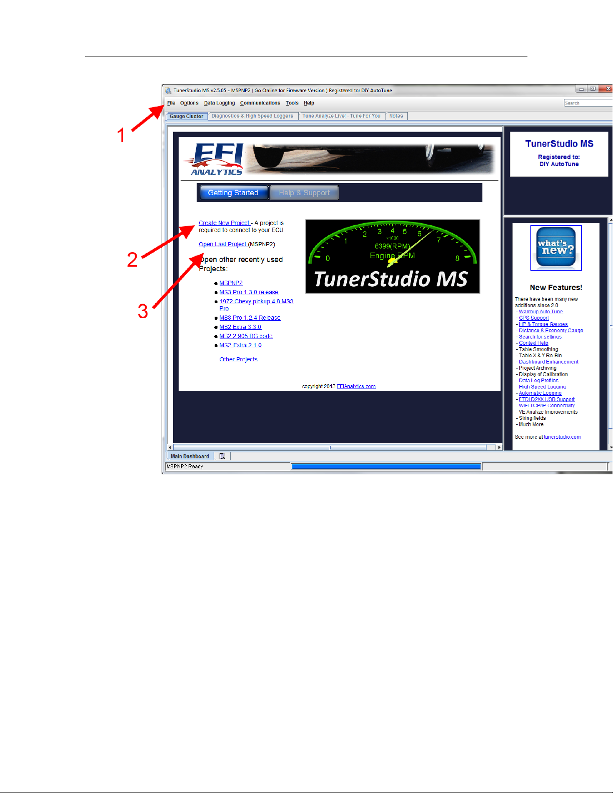
Once TunerStudio opens, you will be presented with the start screen as shown below.
DIYAutoTune.com MS3-Pro manual version 1.036, firmware 1.3.4, 6/10/2015 Page 15
2.1 TunerStudio 2 INSTALLING SOFTWARE
At this point, you’d normally use the screen to create a project or open one; this will set up Tuner-
Studio with the configuration it needs to communicate with your ECU or allow you to view tune files
offline. You can create or open a new project under the file menu (1), or use this menu to open a new
tune for offline viewing. There are also command links to create a new project (2) or open a recent
project (3).
The Help and Support button brings up links to documentaion and support forums for the MS3-Pro
as well as other systems in the MegaSquirt line.
Note that if you open a tune file from this screen, it will go into a temporary project and TunerStudio
will not connect to the MS3-Pro until you create or open a project for connecting to the MS3-Pro.
2.1.2 Creating a project
Selecting “New Project” from the File menu opens a wizard to create a new project. It will bring up a
screen like the one below. At this point, you will want to have the MS3-Pro powered up (see section 4
for wiring details) and connected to the laptop with either the USB or RS232 cable. The MS3-Pro will
need to be powered through the 12 volt supply; it cannot be powered off the laptop.
DIYAutoTune.com MS3-Pro manual version 1.036, firmware 1.3.4, 6/10/2015 Page 16
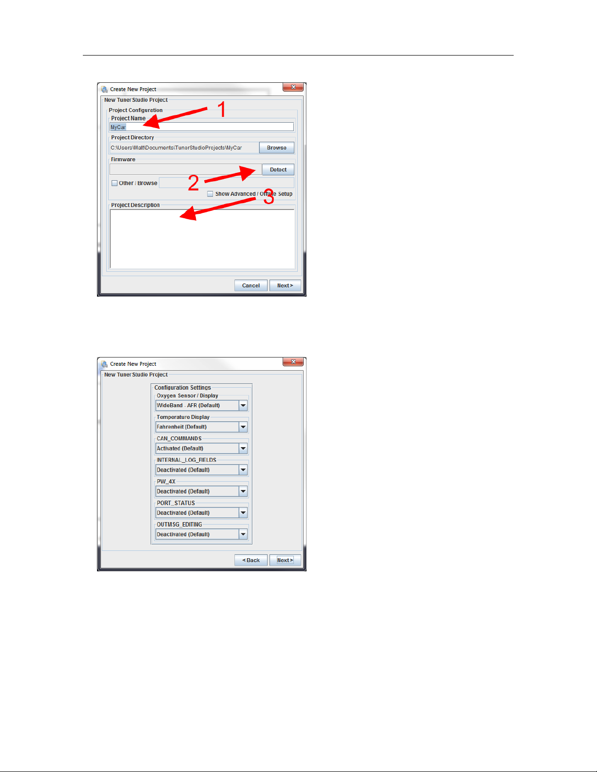
2.1 TunerStudio 2 INSTALLING SOFTWARE
You can enter a name for the project in (1). Next, click the Detect button (2). TunerStudio will
detect what firmware is on your MS3-Pro. If it does not have a definition file, it will prompt you to
download one from the Internet, which TunerStudio will handle automatically for any standard release
version of the MS3-Pro firmware. You can also enter notes about this project in (3).
Clicking Next will bring up a screen where you can select project specific settings.
The exact settings shown will depend on your firmware. These settings are covered in more detail
in section 5.1.
Clicking Next will bring up a communications test screen.
DIYAutoTune.com MS3-Pro manual version 1.036, firmware 1.3.4, 6/10/2015 Page 17
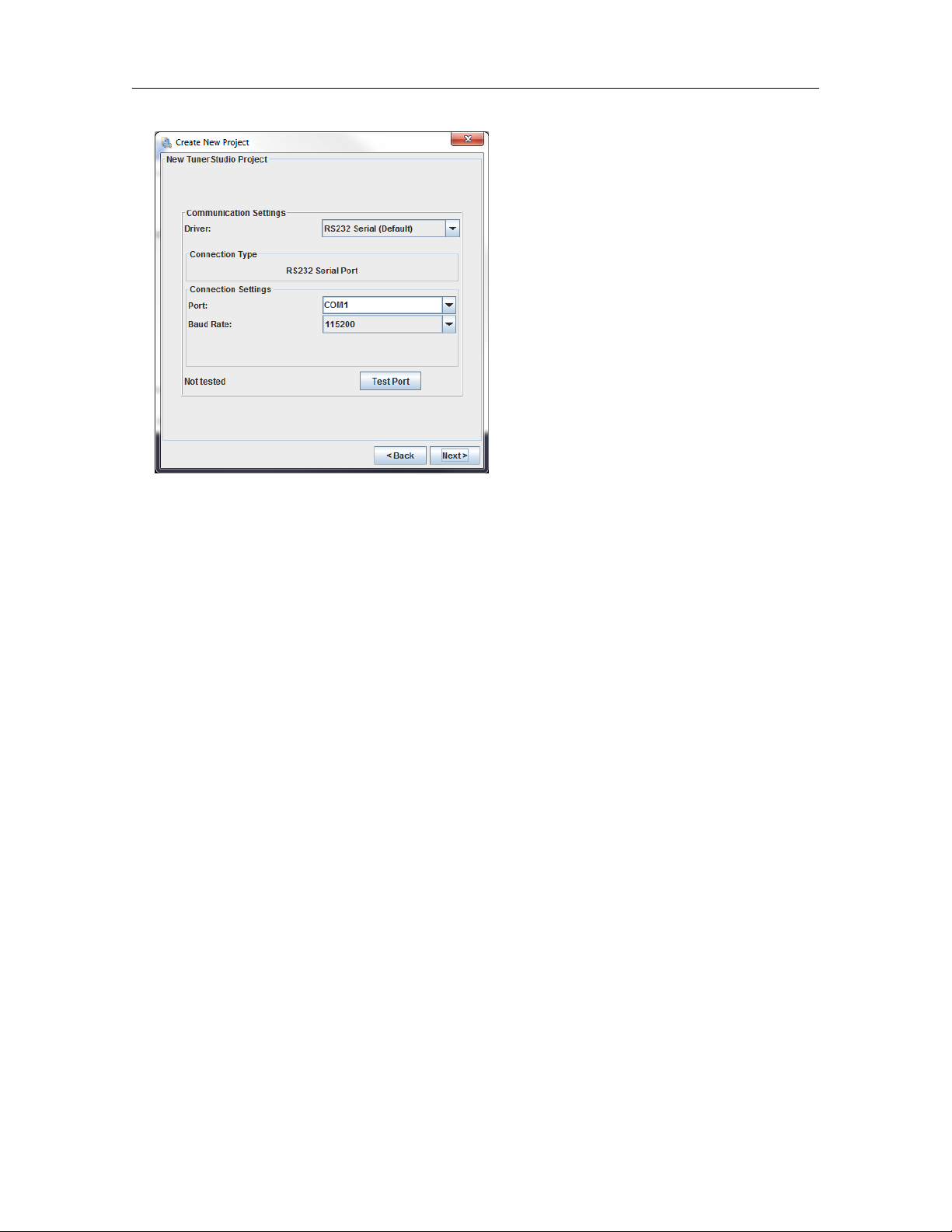
2.1 TunerStudio 2 INSTALLING SOFTWARE
Driver options include:
1. RS232 serial. Use this for connecting to the MS3-Pro’s RS232 port without a USB adapter.
2. USB and wireless. This setting can be used with a Bluetooth adapter, the MS3-Pro’s inter-
nal USB port, or DIYAutoTune.com’s USB-2920 adapter on the MS3-Pro’s RS232 port. This
supports several connection types:
(a) RS232 Serial Interface. Use with USB adapters not sold through DIYAutoTune.com.
(b) FTDI - D2XX Driver. Use with the MS3-Pro’s internal USB port, DIYAutoTune.com’s USB-
2920 adapter, or other USB converters using a FTDI chipset.
(c) TCP/IP - Wifi Driver. Use with WiFi to serial adapters.
3. RS232 Alternate Blocking. This one was interoduced as an alternate mode for USB adapters
with a Prolific chipset, which can be troublesome with standard RS232 settings.
4. Aggressive Driver Reinitialize. Re-initializes the port every time you connect. Use if you have
a Bluetooth adapter that fails to reconnect. Most applications do not need this.
5. K-Line Driver. Not used with MS3-Pro.
Note that some of these options may be removed in future TunerStudio releases. Many of them were
developed as workarounds for specific issues, and future software upgrades may render several of
these unnecessary.
MS3-Pro normally runs at a 112500 baud rate.
After clicking Next, TunerStudio’s final project setup screen lets you select a gauge display.
DIYAutoTune.com MS3-Pro manual version 1.036, firmware 1.3.4, 6/10/2015 Page 18

2.1 TunerStudio 2 INSTALLING SOFTWARE
This display will show the gauges and indicators cycling through their range of readings. There are
several ready to run gauge options that you can select from the drop down menu at the top. Checking
the “other” box allows you to load custom dash files. You can edit any gauge cluster once the project is
opened, or load an alternate gauge cluster. Click “Finish” to confirm your gauge selection and launch
the new project.
2.1.3 TunerStudio main screen
Once you’ve made a project, TunerStudio will bring up its main screen.
DIYAutoTune.com MS3-Pro manual version 1.036, firmware 1.3.4, 6/10/2015 Page 19

2.1 TunerStudio 2 INSTALLING SOFTWARE
The screen is divided into several sections.
•The title bar at the top displays the current TunerStudio version, the project name, and when
connected to the MS3-Pro, the firmware version.
•The menu bar at the top deals mostly with TunerStudio functions, such as loading and saving
files. They also allow for calibrating the sensors.
•The large row of buttons bring up menus to access the settings in the ECU.
•The row of tabs below the buttons lets you select four different screens:
–Gauge Cluster: Displays basic information about the sensor readings, ECU calculations,
and status.
–Diagnostics & High Speed Loggers: These are used for various specialized troubleshooting
functions; see section 8 for more detail.
–Tune Analyze Live! Tune For You: This allows TunerStudio to recalculate new fuel tables
based on oxygen sensor feedback.
–Notes: A text editor for taking notes.
•You can change any gauge or indicator in the cluster by right-clicking on it and swapping it to a
different function.
•There is a second set of tabs at the bottom of the gauge cluster that allows you to set up multiple,
separate gauge clusters. Click on the rectangular icon to create a new cluster.
DIYAutoTune.com MS3-Pro manual version 1.036, firmware 1.3.4, 6/10/2015 Page 20
Table of contents


