Megger Ferrolux FL 10 User manual

Operating Instructions
Date of release: May 2005
EN
Ferrolux FL 10
Audio Frequency Receiver FLE 10
Leitungsortung
Line Locating
Rohrleitungsnetze
Water Networks
Kommunikationsnetze
Communication Networks
Elektrizitätsnetze
Power Networks
Mess- und Ortungstechnik
Measuring and Locating Technologies

2man_fle10_en_03-4.doc

man_fle10_en_03-4.doc 3
FERROLUX® FLE 10

4man_fle10_en_03-4.doc
TABLE OF CONTENTS
1. GENERAL INFORMATION ............................................................11
1.1 Consultation by Megger............................................................. 11
1.2 Terms of Warranty.....................................................................12
1.3 Safety Instructions .....................................................................13
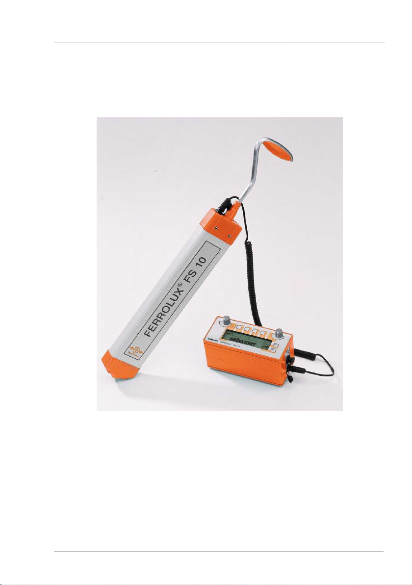
2. TECHNICAL DESCRIPTION ‘FERROLUX® FL 10’ ......................15
2.1 Application .................................................................................15
2.2 Technical Specification ‘FERROLUX® FLE 10’ .......................16
2.3 Technical Data Mini-Antenna ‘FLA 10’ ...................................... 17
2.4 Technical data of the Step voltage probe DEB 3–10 ................ 18
2.5 Items Supplied and Accessory Items ........................................19
3. HOW TO OPERATE RECEIVER ‘FERROLUX® FLE 10’..............21
3.1 Receiver Controls ......................................................................21
3.2 How to Switch the Receiver On and Off....................................22
3.3 How to Switch the Display Lighting On and Off ........................22
3.4 How to Adjust Sensitivity ...........................................................23
3.5 How to Adjust the Volume .........................................................24
3.6 How to Set the Frequency Range .............................................25
3.7 How to Switch Over Between Minimum / Maximum /
Super-Maximum ........................................................................27
3.8 How to Set the Frequency Filter (SignalSelect / Sine Signal) ...29
3.9 How to Select Measurement of Depth and Current ..................32
3.10 Recording and storage of records .............................................33
3.10.1 The start of a record ...........................................................35
3.10.2 The storage of a measuring value......................................35
3.10.3 The termination of a record ................................................36
3.11 The representation of records as diagram ................................37
3.11.1 The start of the diagram representation.............................37
3.11.2 The representation of a diagram ........................................38
3.11.3 The interpretation of a diagram ..........................................39
3.11.4 The representation of the minimum-diffusion in the diagram40

man_fle10_en_03-4.doc 5
3.12 Evaluation of Indicated Values and Acoustic Signals ............... 41
3.13 Earphone Connection ............................................................... 42
3.14 How to Set the Unit of Depth Measurement ............................. 42
3.14.1 How to Set the Unit ............................................................ 42
3.14.2 Shift Line / Probe ............................................................... 42
3.15 How to Select Different Receiving Frequencies........................ 43
3.16 Matching for ‚SignalSelect‘........................................................ 43
3.16.1 Use..................................................................................... 43
3.16.2 Conditions .......................................................................... 43
3.16.3 Equipment .......................................................................... 44
3.16.4 Preparing the matching process ........................................ 44
3.16.5 Performing the matching.................................................... 45
3.16.6 Troubleshooting ................................................................. 46
3.17 How to Determine the Direction of a Line ................................. 46
4. OPERATING THE MINI ANTENNA FLA 10 .................................. 47
4.1 General...................................................................................... 47
4.2 Locating with the Maximum or Minimum method...................... 47
4.3 Locating with ‚SignalSelect‘....................................................... 48
5. OPERATION OF THE STEP VOLTAGE PROBE DEB 3-10........ 49
5.1 General description ................................................................... 49
5.2 Insertion and removal of the capacitive plates or spikes .......... 51
5.3 Locating of the cable route ........................................................ 52
5.4 Locating of faults ....................................................................... 53
6. CARE, MAINTENANCE AND REPAIR.......................................... 55
6.1 General...................................................................................... 55
6.2 How to Replace the Batteries.................................................... 55
6.3 Repair........................................................................................ 56

6man_fle10_en_03-4.doc

man_fle10_en_03-4.doc 7
Definition of Symbols:
Some special paragraphs are marked with a symbol. The following three
symbols will be used:
Safety instruction
TIP ! Practical hint or example from practical experience
i Information:

8man_fle10_en_03-4.doc

man_fle10_en_03-4.doc 9
EC Declaration of Conformity
We, the company
Hagenuk
Kabelmesstechnik GmbH
Röderaue 41
D-01471 Radeburg
declare under sole responsibility that our product
FERROLUX® FLE 10
is in conformity with the provisions of the directive of the Council
of the European Community for the harmonization of the legal
regulations of member states on Electromagnetic Compatibility
(EMC Directive 89/336/EWC).
The electromagnetic compatibility was tested according to the
following standards:
EN 50081 Interference emission, EN 61000-6-2 Interference
steadfastness, EN 55011 Product standard, EN 61000-4-2 Elec-
trostatic discharge and EN 61000-4-4 Fast transient electrical
disruptive factors
The fulfilment of the low voltage guidelines was tested according
to the following standards: EN 61010-1 Safety regulations for
electrical measuring and controlling instruments and laboratory
as well as EN 60529 Ways of protection through casings
Radeburg, 2003-06-13

10 man_fle10_en_03-4.doc

man_fle10_en_03-4.doc 11
1. GENERAL INFORMATION
1.1 Consultation by Megger
These Operating Instruction are intended to help you solve any questions
and problems as fast and easily as possible. Please start with reading the
manual whenever some problem should arise.
If, however, some question should remain unanswered, please contact one
of the following addresses:
Megger Limited
Seba Dynatronic
Mess- und Ortungstechnik GmbH
Archcliffe Road
Kent CT17 9EN
T: +44 1304 502100
F: +44 1304 207342
E: uksales@megger.com
Dr.-Herbert-Iann-Str. 6
D - 96148 Baunach
T: +49 9544 68 – 0
F: +49 9544 22 73
E: sales@sebakmt.com
Hagenuk KMT
Kabelmesstechnik GmbH
Megger USA
Röderaue 41
D - 01471 Radeburg / Dresden
T: +49 35208 84 – 0
F: +49 35208 84 249
E: sales@sebakmt.com
Valley Forge Corporate Centre
2621 Van Buren Avenue
Norristown, PA 19403 USA
T: +1 610 676 8500
F: +1 610 676 8610
Megger
All rights reserved. No part of this handbook may be copied by photographic or other means
unless Megger have before-hand declared their consent in writing. The content of this hand-
book is subject to change without notice. Megger cannot be made liable for technical or print-
ing errors or shortcomings of this handbook. Megger also disclaims all responsibility for dam-
age resulting directly or indirectly from the delivery, supply, or use of this matter.

12 man_fle10_en_03-4.doc
1.2 Terms of Warranty
Megger will accept a warranty claim brought forward by a customer for a
product sold by Megger under the terms stated below.
Megger guarantees that at the time of delivery Megger products are free
from faults in material and workmanship which would reduce their value
and serviceability to a large degree. This warranty does not cover any error
in the software supplied. During the warranty period Megger will repair
faulty parts or replace them with new parts or parts as new (with the same
usability and life as new parts) at their discretion.
Further warranty claims, in particular those from consequential damage,
cannot be accepted. Each component and product replaced in accordance
with this warranty becomes the property of Megger.
All warranty claims versus Megger expire after a period of 12 months from
the date of delivery. Each component supplied by Megger in the context of
warranty will also be covered by this warranty for the remaining period of
time, but at least for 90 days.
Each measure to remedy a warranty claim must be carried out exclusively
by Megger or one of their authorised service stations.
It is a precondition for accepting a warranty claim that the customer com-
plains about the fault, in a case of an immediately detectable fault within 10
days from the date of delivery.
This warranty does not cover any fault or damage caused by exposing a
product to conditions which are not in accordance with this specification, by
storing, transporting or using it improperly, or having it serviced or installed
by a workshop not authorised by Megger. No claim will be accepted in case
of wear and tear, will of God, or connection to foreign components.
For any damage resulting from a violation of their duty to repair or re-supply
items, Megger can be made liable only in case of severe negligence or
intention. Any liability for slight negligence is disclaimed.

man_fle10_en_03-4.doc 13
1.3 Safety Instructions
Every person dealing with the assembly, operation, manitenance and repair
of this instrument is required to have read this manual with care.
At the time of supply, this device and its accessories are in line with the
state of the art in safety engineering. Due to the course of operations,
however, there may be places and parts on the device and its accessories
which cannot be protected optimally without interfering with its function and
operation by the user. For this reason it is a must that the operator has a
comprehensive personal experience in safety matters in order to protect
the staff and the devices.
GENERAL INFORMATION
Any operation on this device and its peripherals may only be carried out by
trained and / or instructed staff. Keep any other persons away.
This manual shall be available to the supervising, operating and
maintenance staff for reference. You are required to supervise all the time
that all safety regulations are observed when running or servicing the the
equipment.
Using the equipment improperly and for any other than its intended
purpose may result in hazards to life and limb, to the instrumentation and
the systems connected to it and may jeopardise the efficient operation of
the device (UVV, German Prevention of Accidents Regulation). You are
only allowed to use this device to the purpose stated by its manufacturer.
Operate the device and its peripherals only if they are in a good technical
condition. Never use any foreign parts on the device and its peripherals,
otherwise the required safety cannot be guaranteed. Abstain from any
mode of operation which might jeopardise the safety of the device.
In any case of trouble that might impair the safety of the staff, the operator
is required to shut the device down at once. The device may be switched
on again only after the damage has been remedied.
ELECTROTECHNICAL INSTRUCTIONS
Connect the device and its accessories according to instructions. Observe
all relevant DIN and VDE regulations.
Any repair and maintenance operations may be carried out only if the
instrument has been switched off (is in a dead state) and only by an
electrotechnical expert according to the Prevention of Acidents regulation
(UVV). According to UVV, a person is regarded an electrotechnical expert if
he or she, due to his or her vocational training, knowledge and experience
as well as knowledge of relevant regulations, is able to assess the job he or
she has been assigned to do and to recognise any possible hazard.

14 man_fle10_en_03-4.doc
In order to avoid any damages to persons or property caused by the opera-
tion of the ‘FERROLUX® FL 10’ or in combination with other devices, al-
ways observe the following safety precautions:
Check whether in the immediate vicinity of the site where the ‘FERROLUX®
FL 10’ will be used there are any unprotected devices / system components
under voltage which you or your instrument may accidentally get into con-
tact with. This applies in particular to components which are under high
voltage (DIN VDE 100) or the voltage of which is not known.
Safeguard these components by means of insulating covers. If it is impos-
sible to do so for technical reasons, de-energize them or have them de-
energized for the time of your activity on this site. Before doing so, consult
the responsible supervisor and ask him to give his permission. Make sure
that all measures have been taken properly, e.g. by taking check meas-
urements by means of a meter the proper functioning of which you have
tested beforehand.

man_fle10_en_03-4.doc 15
2. TECHNICAL DESCRIPTION ‘FERROLUX® FL 10’
2.1 Application
Our Line and Fault Locating System ‘FERROLUX® FL 10’ is used for pre-
cisely locating metal lines such as cables and pipework laid out in the
ground and for determining their depth below the surface. Furthermore it
can be used for detecting the location of faults on cables or lines.
The main field of application of our ‘FERROLUX® FL 10’ is in the location
finding of routes and faults in the following fields: Public power supply, tele-
communication services, water supply systems and civil engineering for
drawing up building plans and for the preparation of digging operations.
For route locating, receiver ‘FERROLUX® FL 10’ offers you a choice of 4
frequency ranges to implement different locating methods.
Frequency ranges:
•Range for passive locating methods
•Ranges for active locating methods using specific transmitter fre-
quencies as emitted by transmitters ‘FERROLUX® FLG 10’,
‘FERROLUX® FLG 50’ or ‘FERROLUX® FLG 200’
Locating methods:
•Location finding by the standard-minimum technique
•Location finding by the standard-maximum technique
•Precision location finding by the super-maximum technique
•Indication of signal flow direction by ‘SignalSelect’
•Automatic depth and current measurement
•Location of lay fields
•Cable selection with mini aerial (optional extra)
•Locating finding of sheath faults with sensor (optional extra)
•Depth measurement (digital + 45° technique)
•Fault location finding by the inductive method (optional extra)

16 man_fle10_en_03-4.doc
2.2 Technical Specification ‘FERROLUX® FLE 10’
Receiving frequencies
Passive:
Active:
50 Hz / 60 Hz / 100 Hz /120 HZ
491 Hz, 982 Hz, 8440 Hz
Dynamic range
50Hz
491Hz
982Hz
8440Hz
(in relation to = 1 m)
10mA ... 10,000A 120dB
400µA ... 400A 120dB
180µA ... 180A 120dB
20µA ... 20A 120dB
Depth measurement
Measurement range
Tolerance
(491 / 982 / 8440 Hz only)
0.13 m ... 7 m
±5 % at the depth of 1.00 m
Current measurement
Current measuring range
Tolerance
1mA ... 400A / 180A / 20A
±10 %
Measuring data memory
Number of records
Number of measuring values
Total memory
(only for the trace sensor FS 10)
99
99 per record at maximum
413 measuring values at maximum
Indication
Numerical indication
Bar-graph indication
Read-out of text, selectable
to be supplied on demand
Power supply
Operating life
Alcaline 4 x LR 6 >20h
NiCd / NiMh 4 x R6 >13h
Weight
approx. 1.5 kg
Dimensions
220mm x 100mm x 110mm
Environmental conditions
Operating temperature range
Storage temperature range
Relative humidity
according to DIN EN 60068-1
-20°C to + 55°C
-40°C to + 70°C
30°C / 93%

man_fle10_en_03-4.doc 17
Enclosure protection
Protection against dust and water
according to EN 60529
IP 54
2.3 Technical Data Mini-Antenna ‘FLA 10’
Receiving frequencies
active
491 Hz, 982 Hz, 8440 Hz
Dynamic range
491Hz
982Hz
8440Hz
(based on = 0.2 m)
1.5mA ... 1500A
120dB
500µA ... 500A 120dB
50µA ... 50A 120dB
Weight
approx. 125g
Dimensions
without connecting cable
35mm x 53mm x 18mm
Environmental conditions
Working temperature
Storage temperature
humidity, relative
according to DIN EN 60068-1
-20°C to + 55°C
-40°C to + 70°C
30°C / 93%
Protection class
Dust and water protection
according to EN 60529
IP 54

18 man_fle10_en_03-4.doc
2.4 Technical data of the Step voltage probe DEB 3–10
Reception frequencies
with generator only
491 Hz, 982 Hz, 8440 Hz
Sensitivity
491 Hz
982 Hz
8440 Hz
Related to +3 dB
60 µV
50 µV
80 µV
Dynamic range
139 dB
Weight
2,5 kg
Dimensions without spikes / plates
57 cm x 69 cm x 5 cm
Environmental conditions
working temperature range
storage temperature range
air humidity, relative
according to DIN EN 60068-1
–20 °C to +55 °C
–40 °C to +70 °C
93 % at 30 °C
Protection class
dust and water protection
according to EN 60529
IP 54

man_fle10_en_03-4.doc 19
2.5 Items Supplied and Accessory Items
Basic equipment
FLE 10
FS 10
VK 13
Accessory items
Headphone KS 10
PC-Cable
GPS-Tracer
Sensors
Mini antenna FLA 10
Microphone FLM 10
Step voltage sensor
Audio frequency generators
FERROLUX® FLG 10
FERROLUX® FLG 50
FERROLUX® FLG 50
FM 9890-S (982 / 9820 Hz)

20 man_fle10_en_03-4.doc
This manual suits for next models
1
Table of contents
Other Megger Receiver manuals