MEI UPS10000 User manual

MESTA ELECTRONICS, INC.
Uninterruptible
Power
System
Owner's Manual
MODELS: UPS10000, UPS15000, UPS20000, UPS25000, UPS30000,
UPS50000
11020 Parker Drive N. Huntingdon, PA 15642
412/754-3000
SAVE THESE IMPORTANT
SAFETY INSTRUCTIONS

Models: UPS10000/3-20-1 – UPS50000/3-20-2
i
Table of Contents
1. INTRODUCTION ..................................................................................................................................1
2. INSTALLATION ....................................................................................................................................3
2.1 ADDING AUXILIARY BATTERY CABINETS TO YOUR UPS SYSTEM........................................7
2.2 COMMUNICATIONS LINKS (Rear Panel Hardware Configuration) ..............................................8
3. SYSTEM DESCRIPTION....................................................................................................................12
3.1 PRINCIPAL COMPONENTS........................................................................................................12
3.2 THEORY OF OPERATION ..........................................................................................................13
4. OPERATING PROCEDURE...............................................................................................................20
4.1 SYSTEM TURN-ON.....................................................................................................................20
4.2 TRANSFERING BETWEEN "ON UPS" AND "ON BYPASS" MODES OF OPERATION ............23
4.3 SYSTEM TURN-OFF ...................................................................................................................24
4.4 DIAGNOSING PROBLEMS .........................................................................................................25
5. FRONT PANEL KEYPAD & LCD OPERATION..................................................................................26
5.1 SYSTEM SOFTWARE COMMANDS (via the front panel)...........................................................26
5.2 LCD MAIN MENU DISPLAY ........................................................................................................26
5.3 LCD SUB-MENU DISPLAYS .......................................................................................................30
5.3.1 DISPLAY #1 Screen.............................................................................................................30
5.3.2 DISPLAY #2 Screen.............................................................................................................31
5.3.3 DISPLAY ALARMS Screen ..................................................................................................32
5.3.4 MANUAL BATTERY TEST Screen ......................................................................................33
5.3.5 SELECTABLE PARAMETERS Screen ................................................................................34
5.3.6 AUTOMATIC BATTERY TEST SETUP Screen ...................................................................35
6. SYSTEM SOFTWARE COMMANDS (via the rear panel RS232 interface)........................................36
7. TROUBLESHOOTING........................................................................................................................39
7.1 FAULT MESSAGES ON THE BOTTOM LINE OF DISPLAY #1 or #2 SCREENS ......................40
7.2 SHUTDOWN, OVERLOAD, DIAGNOSTIC, AND WARNING ALARM MESSAGES ...................41
7.3 HISTORICAL DATABASE DISPLAY INFORMATION .................................................................44
8. MAINTENANCE..................................................................................................................................46
8.1 SYSTEM STORAGE....................................................................................................................46
8.2 OPENING THE UPS CABINET....................................................................................................46
8.3 REMOVING AND REPLACING BATTERIES ..............................................................................47
8.4 BATTERY TESTING ....................................................................................................................51
8.5 OTHER PREVENTIVE MAINTENANCE......................................................................................53
9. EXTERNAL BATTERY CABINETS ....................................................................................................55
APPENDIX A. UPS SPECIFICATIONS BY MODEL...............................................................................61
APPENDIX B: REAR PANEL RELAY CONTACT FUNCTIONAL OPERATION ....................................68
APPENDIX C. WARRANTY/SERVICE AND REPAIR ............................................................................69

Models: UPS10000/3-20-1 – UPS50000/3-20-2
ii
List of Illustrations
Figure 1 UPS Cabinet Enclosure.............................................................................................................3
Figure 2 Isolation Transformer.................................................................................................................4
Figure 3 UPS External Wiring..................................................................................................................4
Figure 4 AC Wiring Terminal Block..........................................................................................................6
Figure 5 Rear Panel Hardware Configuration..........................................................................................9
Figure 6 Location of Principal Components...........................................................................................12
Figure 7 Front Panel Configuration........................................................................................................13
Figure 8 System Block Diagram ............................................................................................................15
Figure 9 Power Wiring Diagrams...........................................................................................................16
Figure 10 System Circuit Boards ...........................................................................................................19
Figure 11 Size 1 & 2 UPS Battery Tray Configuration ...........................................................................50
List of Tables
Table 1 Customer Site Breaker & Wiring Requirements..........................................................................5
Table 2 AC Input & Load Wire Size and Torque Requirements ..............................................................5
Table 3 RS232 Technical Specification Summary...................................................................................9
Table 4 UPS Software Parameters........................................................................................................37
Table 5 Screen Messages flashed at bottom of Display #1 or #2..........................................................40
Table 6 Shutdown, Overload, Diagnostic, and Warning Alarms ............................................................42
Table 7 Battery Cabinet Specifications..................................................................................................55
Table 8 External Battery Wire Size and Torque Requirements .............................................................56
Table 9 UPS Internal Battery Time at Various Loads ............................................................................57
Table 10 Total System Backup Time with Single External Battery Cabinet...........................................57
Table 11 Battery Cabinet Amp Ratings vs. UPS KVA Rating ................................................................58

1
1. INTRODUCTION
As computers become increasingly fundamental to today’s businesses, protection against power
disruptions has never been more critical; and since vital data and hardware are threatened by routine
sags, surges, spikes, and transients – as well as major blackouts – protection must be constant and
instantaneous.
The Mesta UPS system provides this kind of comprehensive protection by maintaining a clean, well-
regulated flow of power to critical loads, regardless of the quality of incoming AC line power. It remains
in a constant state of readiness, so there is no time delay in compensating for AC line failures.
Unique microcontroller intelligence plus state-of-the-art components and manufacturing procedures
yield outstanding capabilities in the Mesta UPS system. Using a proprietary pulse-width-modulation
technique, the microcontroller directs the system to produce a very low harmonic, high quality sine
wave output – perfectly matched in phase and voltage to the AC power line. The result is a completely
seamless transfer of the load from the inverter to the utility and vice versa during a power disturbance
or outage.
This seamless transfer feature, combined with high frequency switching and custom magnetics, results
in a high operating efficiency of 94 percent at full load, coupled with low harmonic distortion.
Because the microcontroller continually monitors the load and the power line, the Mesta UPS system:
•Starts under load with no damage to itself or the load.
•Handles nonlinear loads – loads that require users of other UPS systems to buy more
expensive, higher rated units than they would otherwise need.
•Provides current limiting and short-circuit protection. The UPS provides a 300% overload
current limit for a finite time, and a short circuit placed directly across the output will not
damage the UPS or the load.
The Mesta UPS system incorporates large scale integration, and its modular design provides for quick
and easy maintenance should it ever be needed. Straightforward controls make the Mesta UPS easy to
operate; and audible and visual signals provide clear indications of system status. In the event of a
power line outage, the system:
•Draws power from the system batteries to continue uninterrupted power to the load until
battery energy is depleted (usually 10 – 30 minutes at full load with internal batteries,
depending on model number and configuration– see specifications for exact time).
•Sounds an intermittent alarm after ten seconds (the ten-second delay eliminates nuisance
alarms from minor fluctuations) and displays on the LCD front panel display the reason for
the alarm.
•Sounds another alarm when the usable battery charge has declined to 20 percent of its full
capacity.
•Automatically goes into a state of inactivity once regulated output can no longer be
maintained due to batteries being fully discharged, waiting for the return of AC line
availability. During this state of inactivity the controls will continue to look for the AC power
to return in order to restore normal operation. If no AC power returns, however, after 2 hours
the entire system will shut down to protect its batteries from deep discharge.

2
Once the AC power returns, the system’s microcontroller employs optimum charging techniques to
extend battery life while minimizing charging time. The microcontroller follows a unique algorithm by
which it regulates the charging process and enables a minimal recharging time.
WARNING
Your UPS may contains up to twenty (depending on model) 12 volt batteries wired in series providing
a total nominal DC voltage of up to 240 volts. This voltage, if present, is used to power the UPS when
the AC utility is not available. Because of the presence of this high voltage energy source, even when
the UPS is not directly connected to the utility, certain precautions must be taken to avoid possible
injury should you need to unlock and enter this unit. Before attempting to unlock or enter the unit,
read the section of this manual on “Maintenance” for important safety precautions. Otherwise,
maintenance personnel may be exposed to an electrical shock hazard that could result in death or
injury, or damage to the UPS or its electrical loads.
WARNING
Always keep all panels and the front door locked. Always store the keys that unlock the unit in a safe
place. DO NOT keep the keys in the lock of the unit where someone unqualified or unsupervised may
inadvertently open the main unit or any ancillary units. Leaving the unit unlocked, or leaving keys in
the lock, may expose personnel to an electrical shock hazard that could result in death or injury, or
damage to the UPS or its electrical loads.

3
2. INSTALLATION
Cabinets – The Mesta Electronics UPS system and optional auxiliary battery cabinets are supplied in
cabinets of several sizes, which are indicated by the last digit in the model number. Please reference
Appendix A for dimensions of enclosures. If UPS system is configured with internal batteries, Appendix
A contains their quantity and capacity.
Figure 1 UPS System Cabinet Enclosures
Battery Cabinet UPS Cabinet

4
Unpacking: Before unpacking your unit, examine the shipping carton for damage. If there is any
obvious damage, report it immediately to the dealer or carrier. If no damage is found, unpack the unit
and inspect it for shipping damage. Again, in case of any damage, report it directly to the dealer or the
carrier.
Environment: The MESTA UPS is designed to be used in an environment with a temperature range of
0 to 40 degrees C and relative humidity of 0 to 95%, without condensation. The site should not be
excessively dusty or dirty. If the site is excessively dusty or dirty, contact the manufacturer about the
possibility of adding external air filters to the front of the unit to filter the intake air to the UPS. If
excessive dirt is allowed to enter the unit, the fans and/or heat sink fins could become clogged with dirt,
thus requiring excessive maintenance. Clearances should be provided to the top, front and back of the
unit so as not to block air inlets and outlets, or rear mounted connectors. Also, keep the top of the unit
clear of objects.
Customer-Supplied Wiring
External on-site wiring to supply the UPS must be
provided by the customer (See Figure 3). If a Wye
service feed is available having the same voltage
characteristics as the UPS (e.g. 208/120Y for most
systems), a service feed breaker (see Table 1 for
ratings) must be installed to protect the internal UPS
transfer switch when the UPS is in the "Bypass” mode of
operation. If some other voltage configuration, such as a
delta feed and/or different voltage, is only available, an
isolation transformer (such as one supplied by Mesta
Electronics shown in Figure 2) along with a service feed
breaker is required. Refer to Table 1 for wire, breaker
and transformer ratings for alternative configurations having either 480 or 240 volt service feed
available. View A of Figure 3 shows wiring for such an arrangement.
Figure 3 UPS External Wiring
3 PHASE
208/120Y
SERVICE
X
Y
Z
NEUTRAL
GROUND
SERVICE FEED
BREAKER
(customer supplied)
X
Y
Z
NEUTRAL
3 PHASE
208/120Y
LOAD DISTRIBUTION
PANEL
(customer supplied)
B+ B- X Y Z W X Y Z W
OUTPUTINPUT
TERMINAL BLOCKS
TO EXTERNAL
BATTERY
BREAKER
(optional)
UNINTERRUPTIBLE
POWER SYSTEM
CABINET
EXTERNAL BATTERY
(optional)
B+ B-
IMPORTANT:
X phase leads Y by 120
Y phase leads Z by 120
o
o
GROUND
NOTES:
1. Grounding of enclosures
can be achieved through
conduit approved for such
application and/or wires
connected to points
marked "GND".
OR OPTIONAL
BREAKER/ISOLATION
TRANSFORMER
(SEE VIEW A)
(208/120Y OUTPUT)
ISOLATION TRANSFORMER
DEDICATED
GROUND
Z
Y
X
SERVICE
3 PHASE
X
Y
Z
W
VIEW A:
BREAKER/ISOLATION TRANSFORMER
GROUND
TO
UNINTERRUPTIBLE
POWER SYSTEM
INPUT
GNDGND GND GND
NEUTRAL
GROUND
Figure 2 Isolation Transformer

5
Table 1 Customer Site Breaker & Wiring Requirements
UPS Rating
Rating of
Optional
Isolation
Transformer
480V Input
Wiring/ Breaker
Amperage
(to
transformer)
240V Input
Wiring/ Breaker
Amperage
(to transformer)
208/120Y V
Input
Wiring/Breaker
Amperage
(to UPS)
208V Output
Wiring
Amperage (to
Distribution
Panel)
10KVA 15KVA 20 40 50 50
15KVA 25KVA 30 60 70 70
20KVA 25KVA 40 80 90 90
25KVA 30KVA 45 90 100 100
30KVA 40KVA 60 110 125 125
50KVA 60KVA 90 180 200 200
Table 2 AC Input & Load Wire Size and Torque Requirements
UPS Size Tool Allowable wire size Torque (in-lbs.) Torque (N-m)
10-30 KVA 3/16” Allen wrench 2/0 AWG – 8 AWG 120 14
50 KVA 5/16” Allen wrench 350 kcmil -6 AWG 275 31
Location of Unit: The UPS should be in close proximity to the protected equipment: the longer the AC
wire runs, the more voltage drop and more risk of noise getting back into the system.
Voltage/Power Rating: Make sure that the voltage and power rating match the available line voltage
and load requirements. This can be done by comparing the input and output information printed on the
rating plate of the UPS with your requirements.
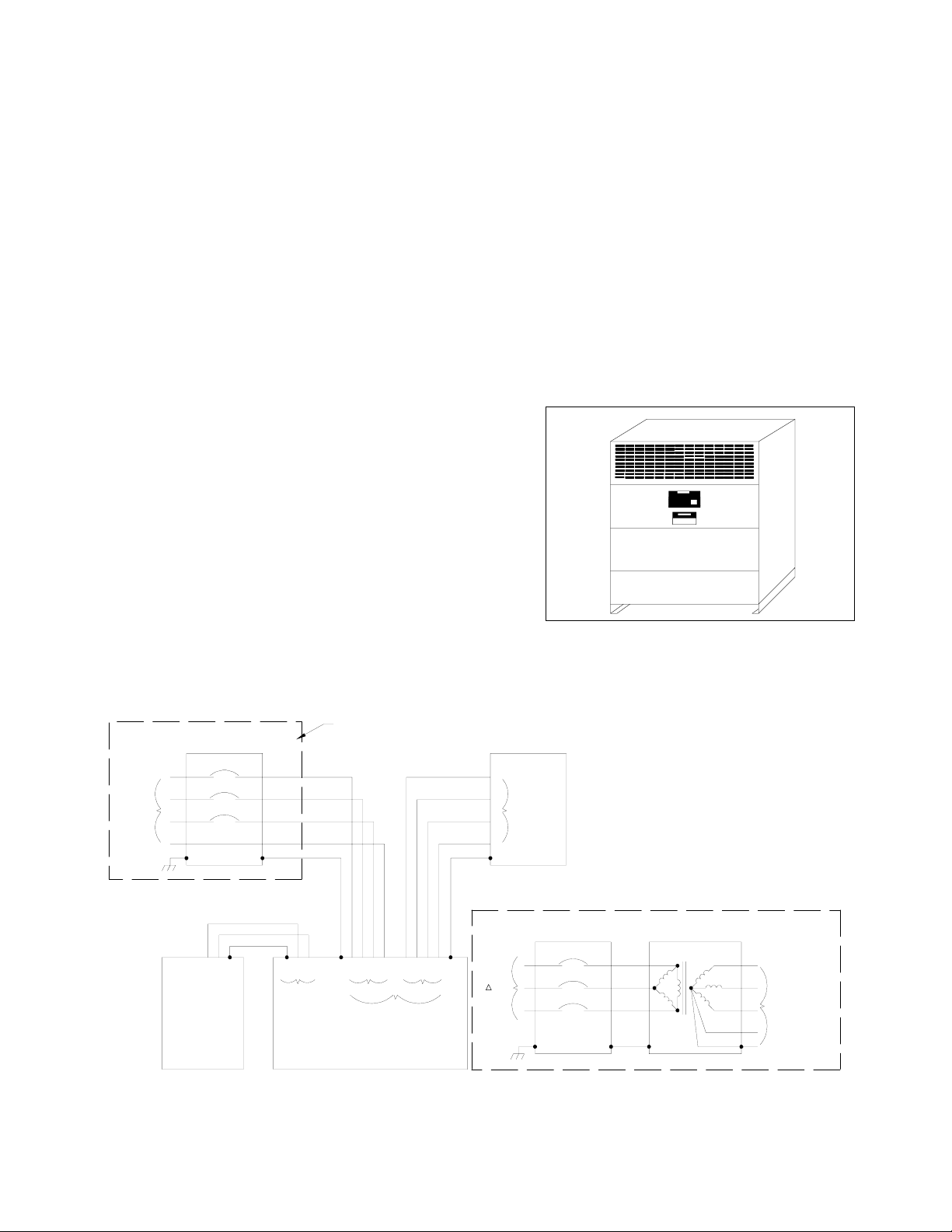
Optional Isolation Transformer Wiring: The wiring instructions are included in the packet of
information that accompanies the transformers. The transformer input has taps to adjust for various line
voltages that have already been selected and set to the nominal position. If the incoming voltage,
however, is other than nominal, other taps can be selected as indicated on the transformer panel.
Wiring from the transformer to the UPS must be capable of handling the 208/120Y amperage shown in
Table 1.
AC Line Input Wiring: Once the voltage and power ratings are verified as compatible with your setup,
and the proper location for the unit has been selected and the unit properly secured there, the UPS is
now ready to be wired for AC input power.
1. On the top of the UPS cabinet there are two pilot holes provided for the incoming and
outgoing AC power. The qualified electrician can use the appropriate punch to prepare the
cabinet for the type of conduit and connector he's going to be using on-site. Drilling or filing
should be avoided, as any metal particles could interfere with the electrical/electronic
equipment.
Once the proper wiring is in place (selected to meet current requirements given in Table 1 and
within the size range given in Table 2), the input wiring can be connected to the leftmost terminal
block marked “INPUT VOLTAGE” on the upper right side of the cabinet. An Allen wrench should be
used to torque the lugs to the specifications given in Table 2. The X, Y, and Z phase wires (where
X-phase leads Y-phase which in-turn leads the Z-phase, all by 120 degrees) must be connected to
the correspondingly marked INPUT VOLTAGE terminals. The neutral wire must be connected to
the INPUT VOLTAGE terminal marked W. Additionally, the AC phases are identified internally with
tape as follows: X phase is unmarked, Y phase is marked with red tape, Z phase is marked with
blue tape, and W phase is marked with white tape. Note that white tape is also used to identify the
“+” wiring of the batteries on the left side of the UPS. This battery wiring marked with white tape on
the left side of the UPS should not be confused with the neutral AC wiring marked with white tape
on the right side of the UPS. If the phase relationship of the input wires is not known, they can be
randomly connected to the X, Y, and Z INPUT VOLTAGE terminals, as long as the neutral wire is

6
connected to the W terminal. If the phase relationship is incorrect (see BAD ROTATION below), the
problem is easily corrected by swapping any two of the X, Y, and Z wires. Refer to Figure 3, UPS
External Wiring, and Figure 4, AC Wiring Terminal Block.
2. A copper lug marked “GND” is supplied on the upper right side of the UPS for the purpose
of grounding the cabinet to earth ground. This lug will accommodate wiring between 8 and
2 AWG for units up to and including 30 KVA, and wiring between 8 and 1/0 AWG for
systems above 30 KVA. A wire size that meets local electrical codes must be selected and
may be routed with the AC supply wiring to the service distribution panel earth ground.
Alternatively, a hole can be drilled and tapped on the backside of the cabinet frame (not
the panel), near the bottom to provide an external chassis ground. Care should be taken
so that metal particles produced by such operation are not allowed to come in contact with
any internal electrical components.
3. If the proper rotation has not been selected, the UPS, when turned "ON", will indicate that
the incorrect rotation has been chosen. The LCD Display #1 or #2 screens will indicate
"AC LINE PROBLEM" on the bottom line, and the status line will read "BAD ROTATION."
In this case the electrician will be required to swap two of the X, Y, and Z wires in the UPS
input to obtain the correct rotation. Note: In addition to checking for proper phase rotation,
the UPS will also examine the phase of each leg and the angle between phases. The LCD
screen will indicate any problems detected.
Figure 4 AC Wiring Terminal Block
XYZW X ZWY
INPUT VOLTAGE
208V/3 Y/60HZ
OUTPUT VOLTAGE
208V/3 Y/60HZΦΦ
Connecting the Load: Wire the UPS “OUTPUT VOLTAGE” terminals to the load distribution panel,
making sure that all loads are off (Refer to Figure 3, UPS External Wiring and Figure 4, AC Wiring
Terminal Block). Terminals marked X, Y, and Z refer to the three phases where the X-phase leads the
Y-phase which in-turn leads the Z-phase, all by 120 degrees. The W terminal is again the neutral of the
3-phase Wye output. Internal wiring to this terminal block is marked with red (Y-phase), blue (Z-phase),
and white (neutral) tape. Refer to Table 1 for current carrying capabilities that this wiring must have and
Table 2 for allowable wire size. An Allen wrench should be used to torque the lugs to the specifications
given in Table 2.
External Battery Cabinet: If an external battery cabinet is supplied with the UPS system, then an
additional DC breaker marked “EXTERNAL BATTERY BREAKER” or “BATTERY BREAKER” will also
be supplied on the left side of the UPS cabinet. A qualified electrician can find the pilot hole for the
External Battery Cabinet wiring just above this breaker in the UPS cabinet. In the same manner as
described for the AC wiring, the electrician would establish the proper punch, install the proper conduit
and wiring, and bring the two external battery wires to the External Battery Breaker. See ADDING
AUXILIARY BATTERY CABINETS.

7
WARNING
Extreme caution must again be exercised so that the polarity of the batteries is preserved as it is
presented to the breaker. The "+" and "-" lugs on the breaker are indicated with "+" on the left and "-"
on the right. The "+" wire will be marked with white tape. If this code is not carefully followed,
maintenance personnel may be exposed to an electrical shock hazard that could result in death or
injury, or damage to the UPS or its electrical loads may occur.
Computer Terminal Connections: It is also suggested, but not required, that you connect a terminal
or computer to the RS232 interface (see paragraph 2.2). Through this communications interface you
can obtain the same useful data available from the front panel LCD screen, along with some additional
diagnostic information.
Remote Status Panel Connections: If the UPS is to be located in a remote area away from
personnel, an optional Remote Status Panel may be purchased that can be placed in a location that is
observable by personnel. Through its wiring interface to the “RELAY CONTACTS” connector on the
back of the UPS, this panel can alert personnel of any problems encountered by the UPS. Wiring
instructions are included with the remote status panel.
Preparation for Turn-On: Having wired your UPS to the AC utility, to the load and to external batteries
(if so equipped), check the wiring with a continuity meter or other means. You may now begin the Turn-
On procedure. See the System Turn-on section of this manual.
2.1 ADDING AUXILIARY BATTERY CABINETS TO YOUR UPS SYSTEM
WARNING
Only qualified technicians or supervised personnel should attempt to connect/disconnect external
battery cabinets to/from the UPS models covered by this manual. ALL of the following WARNINGS
and INSTRUCTIONS should be read and fully understood prior to undertaking this task. Otherwise,
maintenance personnel may be exposed to an electrical shock hazard that could result in death or
injury, or damage to the UPS or its electrical loads may occur.
If your system is configured with internal batteries, additional battery cabinets may be added to your
UPS to extend the backup time of your UPS. If the UPS cabinet does not have internal batteries, than
at least one battery cabinet must be incorporated into the UPS system to provide backup energy. It is
recommended that only battery cabinets supplied by Mesta Electronics be added so that complete
compatibility with your UPS can be guaranteed. Different manufacturers' battery cabinets may possibly
be used, but their use should be cleared with Mesta before doing so. CAUTION - not checking other
battery cabinets with Mesta Electronics may result in serious damage to the UPS and will nullify
warranty and UL compliance.
WARNING
Risk of Electric Shock. Do not attempt to connect/disconnect external battery cabinets to/from the
UPS unless the UPS external battery breaker and all external battery cabinet breakers are OFF.
Otherwise, maintenance personnel may be exposed to an electrical shock hazard that could result in
death or injury, or damage to the UPS or its electrical loads may occur.

8
WARNING
Risk of Electric Shock and Fire. The battery circuit is grounded at the UPS. Do not attempt to
additionally ground the battery circuit. Otherwise, maintenance personnel may be exposed to an
electrical shock hazard that could result in death or injury, or damage to the UPS or its electrical
loads may occur.
Before any work is begun on a Mesta External Battery Cabinet, refer to Chapter 9, “External Battery
Cabinets”, of this manual for complete instructions and detailed wiring diagrams.
2.2 COMMUNICATIONS LINKS (Rear Panel Hardware Configuration)
The communication hardware connectors on the back panel of the UPS consist of a 25-pin for RS232
compatible or current loop serial communications, a 15-pin for custom I/O, and either a 25-pin for 6
signal level relays or a 12-pin for 4 power relay contacts.
•The serial communications connector provides a means for monitoring and/or controlling the
UPS remotely from a computer or terminal via RS232 signaling or 25 ma current loop methods.
Two LEDs on the panel just above the RS232 connector are used to diagnostically indicate
current flow through the TRANSMIT/RECEIVE portions of the 25 ma current loop
communications link if the serial communications is configured in this manner. (Note: current
loop is a method of interconnecting terminals and transmitting signals whereby a mark (binary 1)
is represented by current on the line, and a space (binary 0) is represented by the absence of
current.)
•The custom I/O connector allows for 4 standard dry contact inputs. If a dry contact is used to
short pins 1 and 2 of this connector, the UPS will shut down and trip its own breakers. This is
referred to as a remote shutdown and is used by fire protection or other safety equipment to turn
off the UPS in the event of an emergency. (The remote shutdown is an optional feature. Please
contact the factory for activation of this function.) A dry contact across pins 3 and 4 results in an
audible alarm reset in the remote status panel should "mode 1" be employed to control the
status relays. Pins 14 and 15 provide -12V and +12V supply power to a remote status panel or
custom setup. Other pins can be customized for specific requirements of the end user of this
equipment.
•The relay contacts connectors have dry contact outputs that can be used by the UPS to control
external equipment. The most frequent use is with a remote status panel, where these contacts
are used to control the lights and audible alarm on the panel. Your UPS will come with one of
two types of relay contacts. If your UPS has a 25 pin connector for relay contacts, your unit is
equipped with six low level 24V, 0.1 amp maximum, contacts. If your UPS has a 12 pin
connector for relay contacts, your unit is equipped with four power 120VAC, 10 amp maximum
contacts.

9
Figure 5 Rear Panel Hardware Configuration
SERIAL
COMMUNICATIONS
CUSTOM
I/O RELAY CONTACTS
(LEDs)
Table 3 RS232 Technical Specification Summary
CONNECTOR: 25 pin D female
FORMAT: ASCII, 1 start bit(0), 8 data bits, 1 stop bit(1)
BAUD RATE: 1200
PARITY: None
DUPLEX: Full
PROTOCOL: None used. Interface is simple 3 wire (RXDATA, TXDATA,
and GND) with no hardware or software handshaking.
MESTA SERIAL COMMUNICATIONS:
"DTE" CONNECTOR IBM PCAT COMPATIBLE COMPUTER
SIGNAL PIN PIN SIGNAL
TX
RX
GND
2
3
7
2
3
5
RX
TX
GND
25 pin connector <100 feet 9 pin connector
CURRENT LOOP COMMUNICATIONS:
SIGNAL PIN
ILTXRET
ILTXSRC
ILRXRET
ILRXSRC
14
7
12
11
25 pins <1 mile
ISOLATED
CURRENT LOOP
RECEIVER
ISOLATED
CURRENT LOOP
TRANSMITTER
PC

10
MODEM COMMUNICATION:
"DTE" CONNECTOR
SIGNAL PIN
TXD
RXD
SIG GND
RTS
CTS
DTR
CD
2
3
7
4
5
20
8
MODEM
TELEPHONE
LINE
<100 feet
"DTE" CONNECTOR (female - as seen on back panel):
14
15
16
17
18
19
20
21
22
23
24
25
1 - Earth Ground
2 - TX / TRANSMITTED DATA/
4 - RTS / REQUEST TO SEND/
5 - CTS / CLEAR TO SEND/
6
7 - Signal Ground/CURRENT LOOP TRANSMITTED/
8 - CD / CARRIER DETECT/
9 - +12V
10 - -12V
11 - CURRENT LOOP RECEIVED DATA SOURCE/
12 - CURRENT LOOP RECEIVED DATA RETURN/
13
DATA TERMINAL READY/ DTR -
CURRENT LOOP TRANSMITTED
DATA RETURN/ -
3 - RX / RECEIVED DATA/
"CUSTOM I/O" CONNECTOR:
1
2
3
4
5
6
7
8
9
10
11
12
13
14
15
- Remote Shutdown
- Ground
- Spare Input
- Ground
-12V(50mA max) -
+12V(50mA max) -
Remote Shutdown
Dry Contact (15mA)
Spare Input
Dry Contact (15mA)

11
CONTACTS
RELAY NC C NO
1 3 2 1
2 6 5 4
3 9 8 7
4 12 11 10
LARGE RELAY CONTACTS:
10 11 12
789
456
123
Purchase mating AMP socket 1-480708-0
with suitable pins
NC - Normally closed contact
NO - Normally open contact
C - Common side of contact
Maximum rating of contacts = 120V/10A
See Appendix B for function of relay contacts.
CONTACTS
RELAY NC C NO
1 13 25 12
2 11 23 10
3 9 21 8
4 7 19 6
5 5 17 4
6 3 15 2
SMALL RELAY CONTACTS:
13
12
25
24
23
22
21
20
19
18
17
16
15
14
11
10
9
8
7
6
5
4
3
2
1
: Optional Configuration Available from
factory
NC - Normally closed contact
NO - Normally open contact
C - Common side of contact
Maximum rating of contacts = 24V/0.1 Amp
See Appendix B for function of relay contacts.

12
3. SYSTEM DESCRIPTION
This section points out the main components of the Uninterruptible Power System and discusses the
theory of operation of the unit.
3.1 PRINCIPAL COMPONENTS
The principal components in the Mesta Electronics UPS system are identified in Figure 6. On the front
panel, the 16 key keypad and the LCD readout are found, along with two locks for securing access to
the system. Accessible from the front panel, when the door is closed, are the power controls: two
battery breakers (Main Battery and optional External Battery), rotating transfer switch, and AC line
breaker. On the back of the cabinet are the communications I/O connectors: serial communications
port, custom I/O port and ports for dry relay contact outputs.
Other major components (from top to bottom) are: cooling fans, terminal block connectors, heat sinks
with power semiconductors, circuit boards for controlling the system, capacitor bank, transformer and
its high frequency filtering inductors, and battery shelves (size 1 cabinet with 20 batteries is shown). A
size 1 cabinet with 18 batteries is similar except the bottom battery shelf has only 3 trays of batteries. A
size 2 cabinet is also similar except the 20 battery system has 5 trays of batteries on each of the two
shelves, while the 18 battery size 2 cabinet has 5 trays on one shelf and 4 trays on the other shelf. A
size 3 cabinet does not contain any internal batteries.
Figure 6 Typical Location of Principal Components

13
Front Panel – The front panel (see illustration below) provides real time information about the system
operation on the liquid crystal display (LCD) screen. The keypad enables the system operator to
command the various functions and view a number of informational screens on the 8 line by 40
character LCD display. The TRANSFER REQUEST button is used to initiate a switch between the ON
and BYPASS modes. Three lights indicate system status: the availability of AC power, if the batteries
are discharging, and an indication that the UPS needs attention. An audible alarm has also been
implemented to alert the operator to situations that need attention or the UPS batteries are discharging.
The “TRANSFER REQUEST” push-button switch is used to initiate a transfer of the load to/from the
UPS and the raw utility.
Figure 7 Front Panel Configuration
MESTA ELECTRONICS, INC. UNINTERRUPTIBLE POWER SYSTEM
TRANSFER
REQUEST
AC LINE BATTERY
DISCHARGING
ATTENTION
0
123
456
789
HELP
SELECT
DELETE
ESCAPE
ENTER
ALARM
RESET
3.2 THEORY OF OPERATION
Mesta Electronics was the first to introduce the truly line interactive approach for UPS systems. This is
the technique whereby the UPS maintains its output continuously phase locked and voltage equalized
with the utility so that the critical load is normally supported by two sources.
The system's operation is as follows: the Mesta UPS’ inverter, when first powered on, converts battery
power to AC for the critical load. If the utility voltage is available and within usable voltage and
frequency limits, the UPS output is phase locked to the utility, and a solid state switch is activated to
connect the output to the utility. At this time, both the utility and the inverter are driving the load,
although the inverter output is reduced to slightly below the utility voltage. This enables all of the UPS
output power to be derived from the utility while also providing charge current to the batteries through
the inverter. Once the batteries are fully charged, the inverter voltage is adjusted closer to the utility
voltage to reduce the charging current.
The inverter remains "ON" all of the time that the utility power supplies the load. If the utility power
rises, dips, or totally disappears, the inverter will maintain the voltage to the critical load. The solid state
switch connecting the UPS output to the utility line is a super-fast turn-off switching device which can
be turned off within a microsecond. When the utility goes outside the acceptable voltage, frequency, or
slew rate limits (as set for any given application), the switch is opened, thus disconnecting the utility
and leaving the load to be powered by the inverter only.

14
Mesta's inverter uses a unique pulse-width-modulation (PWM) design that results in a sine wave output
while being able to power non-linear loads without derating. The unit delivers 300% peak transient
overload current (with or without the utility present) for any commonly occurring transient load
conditions (such as load equipment being powered up). The unique current-limit used by Mesta even
allows the UPS output to be short-circuited. Under a short-circuit or other heavy overload condition, the
switch connecting the UPS output to the utility is turned off, and the inverter is current-limited to 300%
of the UPS rated output for a specified period of time. If the overload persists beyond this period of
time, the UPS electronically shuts down until reset by an operator via the front panel keypad/LCD
display. During all such overloads no damage is sustained by the UPS or to any fuses or breakers in
the UPS. The UPS will sustain overloads up to 150% rated load for 1 minute and overloads exceeding
150% rated for .34 seconds (10 and 15 KVA systems) or .17 seconds (20 through 30 KVA).
System Block Diagram - Figure 8 on the next page is a block diagram demonstrating the basic
operation of the Mesta UPS system.
The heart of the system is the master control, which possesses a 16 bit, 16 MHz microcontroller. It
continually monitors all of the important parameters such as input and output currents and voltages,
temperatures, and input and output requirements. It instantly commands the inverter through the gate
drives to generate a high quality sine wave output to the critical load.
The three phase inverter bridge consists of isolated power IGBT (insulated gate bipolar transistor)
devices capable of operating at a high carrier frequency with minimal switching and "ON" losses. The
voltage interface PC board receives the input, output and battery voltages and properly interfaces them
with the master control.
The keypad and LCD, as well as the remote communication blocks, constitute and provide the means
by which the user can communicate with the UPS. The LCD screen consists of an 8 line by 40
character display, making it possible for various instructions and diagnostic comments. The remote
communications block consists of an isolated RS232 communications protocol for either a voltage or
current loop interface. A number of status relay contacts are also provided.
The gate drives are optically isolated devices with both positive and negative supplies that properly
drive the IGBT power devices on and off as commanded by the master. The LC filter reduces the high
frequency harmonics produced by the inverter to the system transformer, and keeps them to a minimal
component of the output voltage.
Surge suppression circuitry on the AC line input provides for input surge/spike protection as per IEEE
C62.41-1980 (formerly IEEE 587) to protect the UPS and the load from being damaged by high voltage
spikes that may occur on the utility feed. The high speed solid state switch is the block containing three
IGBT modules along with proper protection which, when gated "ON", permits the utility to coexist with
the inverter output.
The three phase system transformer has three isolated windings: the inverter, the AC input and AC
output. Both the inverter and AC input windings are connected as a Delta while the output is connected
in a Wye (Y) configuration.
The Transfer Switch permits the user to completely bypass the UPS. When the switch is in the "On
Bypass" position, the load is driven directly by the utility; thus, the operator can shut the UPS down to
perform maintenance. In order for the Transfer switch to go to or to leave the “On Bypass" position, the
master controller must be consulted by pressing the transfer request button and following the
instructions on the display. In fact, the Transfer Switch can not be turned unless the master control
assures proper phase lock and voltage equalization between the inverter output and the utility.

15
The master controller monitors internal and external battery currents, which enables the microcontroller
to determine: a) that the external batteries or battery breakers, if used, are functioning, and b) proper
charging current is sent to the battery systems. The heat sink, inside ambient and room temperatures
are monitored for the protection of the equipment itself.
Figure 8 System Block Diagram
AC Breaker
Surge
Suppr.
3
Φ
AC
Input
High Speed
SS Switch
Maint.
Bypass
Switch
3
Φ
AC
Output
Main Battery Breaker
Ext. Batt.
Breaker
External Battery
Cabinets
Internal
Battery
Ι
Β
Temp Sense
Master
Control
Voltage
Interface
Input
Output
and
Battery
Voltage
Keypad
& LCD
Remote
Commun
RS232 Port
Status Relay Contacts
Gate
Drives
Ι
DC
Ι
L
3
Φ
Inverter
LC
Filter
3
Φ
Inverter
Transformer
Only systems
w/internal batteries
System Power Wiring Diagrams – The system power wiring diagrams are found in Figures 9A and
9B. These wiring diagrams are for a size 1, 20 battery UPS. Similar diagrams can be found posted on
the inside of the door of the UPS. Figure 9A shows the wiring associated with the DC voltage circuitry
whose major components consist of the internal batteries, DC breaker(s), DC Power contactor, inverter,
and inverter output filtering. A size 1, 18 battery UPS has identical wiring, except the group of 2
batteries on the right side of the lower shelf does not exist. A size 2, 20 battery UPS also has identical
wiring except the batteries are configured in groups of two because each tray has two 65 amp-hr
batteries instead of three 38 amp-hr batteries. A size 2, 20 battery UPS has 10 trays of batteries, five
trays on each shelf. A size 2, 18 battery UPS has 9 trays of batteries with 5 trays on one shelf and 4
trays on the other shelf. The AC voltage circuitry shown in Figure 9A is identical for all UPS sizes. It
contains AC voltage circuitry whose main components consist of the AC input and output terminal
blocks, AC breaker, transfer switch, input surge suppression, AC IGBT switches for switching on and
off the input AC, and the 3-phase power transformer.

16
Figure 9 Power Wiring Diagrams
9a) DC Power Wiring w/ Internal Batteries
MESTA POWER INVERTER
To External Battery Cabinet(s)
SIZE ENGR DWG NO REV
A AJA UPS1030KWD 0
SCALE
NTS UPS1030KWD.VSD
SHEET
1 OF 2
MESTA ELECTRONICS, INC.
10 ALLEGHENY SQUARE
GLASSPORT, PA 15045
PHONE: (412) 672-8200
FAX: (412) 672-8208
AJA
DFT
TITLE
POWER WIRING DIAGRAM UPS10000-UPS30000
MAIN
BATTERY
BREAKER
EXTERNAL
BATTERY
BREAKER
White
Black
Rear of Cabinet
Front of Cabinet
Top Shelf of Batteries
(Top View)
Rear of Cabinet
Front of Cabinet
Bottom Shelf of Batteries
(Top View)
Internal
Battery Current
Shunt
White
Black
GND
Precharge Resistor (P/O PC-I)
White
White
White
White Black
+
+
+
Black
White
Blue
Red
Black
+-
Z
INV
X
INV
Y
INV
To AC Side
NOTE:
Only included External
Battery Breaker and
associated wiring if
equipped with external
batteries.
DC SIDE POWER
9b) AC Power Wiring w/ Internal Batteries
INPUT
TERMINAL
BLOCK
3 Phase Power Transformer
2 Delta Sources (AC Utility and
Power Inverter). 1 Wye Output.
SIZE ENGR DWG NO REV
A AJA UPS1030KWD 0
SCALE
NTS UPS1030KWD.VSD
SHEET
2 OF 2
MESTA ELECTRONICS, INC.
10 ALLEGHENY SQUARE
GLASSPORT, PA 15045
PHONE: (412) 672-8200
FAX: (412) 672-8208
AJA
DFT
TITLE
POWER WIRING DIAGRAM UPS10000-UPS30000
Black
Blue
Red
White
Black
Red
HIGH SPEED
IGBT SWITCHES
Red
Black Blue
Z
INV
X
INV
Y
INV
To DC Side
Green
Blue
TRANSFER
SWITCH
On
Bypass
Off
On
UPS
Off
Idle
P1
P5
P9
P13
Black
Red
Blue
White
INPUT AC
BREAKER
SURGE
SUPPRESSION
Black
Red
Blue
White
OUTPUT
TERMINAL
BLOCK
Black BlueRed
Black
Red
Blue
White
XYZW XYZW
P3
P7
P11
P15
P4
P8
P12
P16
To Critical
Loads
From Utility
Distribution Panel
(Must be protected with 3
phase breaker as instructed
by Owner's Manual)
GND
Green
AC SIDE POWER

17
9c) DC Power Wiring w/o Internal Batteries
MESTA POWER INVERTER
To External Battery Cabinet(s)
SIZE ENGR DWG NO REV
A AJA UPS50KWD 0
SCALE
NTS UPS50KWD.VSD
SHEET
1 OF 1
MESTA ELECTRONICS, INC.
10 ALLEGHENY SQUARE
GLASSPORT, PA 15045
PHONE: (412) 672-8200
FAX: (412) 672-8208
AJA
DFT
TITLE
BATTERY
BREAKER
White
Black
GND
Precharge Resistor (P/O PC-I)
White
White
White
White Black
+
+
+
Black
White
Blue
Red
Black
+-
Z
INV
X
INV
Y
INV
To AC Side
DC SIDE POWER
9d) AC Power Wiring w/o Internal Batteries
INPUT
TERMINAL
BLOCK
3 Phase Power Transformer
2 Delta Sources (AC Utility and
Power Inverter). 1 Wye Output.
SIZE ENGR DWG NO REV
A AJA UPS50KWD 0
SCALE
NTS UPS50KWD.VSD
SHEET
1 OF 1
MESTA ELECTRONICS, INC.
10 ALLEGHENY SQUARE
GLASSPORT, PA 15045
PHONE: (412) 672-8200
FAX: (412) 672-8208
AJA
DFT
TITLE
Black
Blue
Red
White
Black
Red
HIGH SPEED
IGBT SWITCHES
Red
Black Blue
Z
INV
X
INV
Y
INV
To DC Side
Green
Blue
TRANSFER
SWITCH
On
Bypass
Off
On
UPS
Off
Idle
P1
P5
P9
P13
Black
Red
Blue
White
INPUT AC
BREAKER
SURGE
SUPPRESSION
Black
Red
Blue
White
OUTPUT
TERMINAL
BLOCK
Black BlueRed
Black
Red
Blue
White
XYZW XYZW
P3
P7
P11
P15
P4
P8
P12
P16
To Critical
Loads
From Utility
Distribution Panel
(Must be protected with 3
phase breaker as instructed
by Owner's Manual)
GND
Green
AC SIDE POWER
This manual suits for next models
5
Table of contents
Popular UPS manuals by other brands

HPE
HPE R/T3000 G5 Product End-of-Life Disassembly Instructions

Salicru
Salicru ADAPT user manual

Emerson
Emerson Liebert PowerSure PST quick start guide

OPTI-UPS
OPTI-UPS DS-C33 II Series user manual

CyberPower
CyberPower BU800E user manual

Liebert
Liebert UPStation S VCR232C Installation and instruction manual