KStar YDC9300-0.8 User manual

- 1 -
All rights reserved.
The information in this document is subject to change without notice.
Publish statement
Thank you for purchasing this series UPS.
This series UPS is an intelligent, three phase in single phase out, high frequency online
UPS designed by our R&D team who is with years of designing experiences on UPS. With
excellent electrical performance, perfect intelligent monitoring and network functions,
smart appearance, complying with EMC and safety standards, This UPS has become
standard product meets the world’s advanced level.
Read this manual carefully before installation
This manual is for
Equipment operator
Technical support

- 2 -
Safety Instruction
1. Prohibition
1.1There is a high risk of electric shock from the UPS inside, so please don’t not open
or remove the casing or front panel unless it is operated by authorized technicians,
otherwise warranty becomes void as well.
1.2 Please contact and discuss with distributors before connecting the UPS to following
equipments
Medical equipments which have direct relationship with patients’ life
Equipments like elevators which may do harm to human beings
Similar equipments as mentioned above
1.3 Don’t dispose of the battery with fire so as to avoid explosion
2. Safety notice
1) Output of standard UPS reconfigured with internal batteries may be energized even
if the UPS input is not connected to the utility
2) Do disconnect the UPS input and make sure the UPS is completely off before
moving the UPS or reconfigured the connection; otherwise, there will be potential
electric shock.
3) For the sake of human being safety, please well earth the UPS before starting it.
4) Working environment and storage way will affect the lifetime and reliability of the
UPS. Avoid letting the UPS work under following environment for long time
Area where the humidity and temperature is belong the specified
range(temperature 0 to 40℃, relative humidity 5%-95%).
Direct sunlight and location nearby heat
Area which can be crashed easily
Area with erosive gas, flammable gas, excessive dust, etc.
5) Keep the ventilations in good conditions otherwise the temperature of components
inside UPS will be high and the component and UPS life will be affected.
6) It is forbidden to pour liquid or put any objects into the UPS.
7) Don’t use liquid extinguisher if there is a fire, a dry powder extinguisher is
recommended.

- 3 -
8) Battery life cycle will be shorter as environment temperature rise. Replacing battery
periodically can help to keep UPS in normal status and assure backup time required.
Battery replacement should be done by authorized technician.
9) Keep the UPS in a dry area or environment if it will not be free of operation for long
time. Storage temperature of UPS with internal battery is -20℃to 55℃.extended
backup model without internal battery is -40℃to 70℃.
10) Taking out the UPS or batteries from storage, it is recommended to connect them
with the utility for at least 12 hours per 3 months to avoid battery damage
11) Don’t open the battery, electrolyte inside will do harm to eyes and skin. Please use
plenty of clean water to wash if touching and go to see a doctor right away.

- 4 -
Contents
1.Product Introduction - - - - - - - - - - - - - - - - - - - - - - - - - - - - - - - - - - - - 6
1.1 Application- - - - - - - - - - - - - - - - - - - - - - - - - - - - - - - - - - - - - - - - - - - 6
1.2 Product range - - - - - - - - - - - - - - - - - - - - - - - - - - - - - - - - - - - - - - - 6
1.3 System principle diagram - - - - - - - - - - - - - - - - - - - - - - - - - - - - - - - 6
1.4 Features- - - - - - - - - - - - - - - - - - - - - - - - - - - - - - - - - - - - - - - - - - -7
1.5 Product overview- - - - - - - - - - - - - - - - - - - - - - - - - - - - - - - - - - 7
1.5.1 Product view- - - - - - - - - - - - - - - - - - - - - - - - - 7
1.5.2 LCD Operation instruction- - - - - - - - - - - - - - - - - - - - - - - 8
1.5.3 Display instruction - - - - - - - - - - - - - - - - - - - - - - - - - - - - - - - 11
1.5.4 Rear panel instruction - - - - - - - - - - - - - - - - - - - - - - - - - - - - - - - - - - - - 16
2.Installation- - - - - - - - - - - - - - - - - - - - - - - - - - - - - - - - - - - - - - - 18
2.1 Unpack checking- - - - - - - - - - - - - - - - - - - - - - - - - - - - - - - - - - - - - 18
2.2 Installation procedure - - - - - - - - - - - - - - - - - - - - - - - - - - - - - - - - - - 18
2.2.1 Installation note- - - - - - - - - - - - - - - - - - - - - - - - - - - - - - -18
2.2.2 Installation - - - - - - - - - - - - - - - - - - - - - - - - - - - - - - - - - - - - - 19
2.3 Connection of parallel system - - - - - - - - - - - - - - - - - - - - - - - - - - - - 23
3.Operation- - - - - - - - - - - - - - - - - - - - - - - - - - - - - - - - - - - - - - - -24
3.1 Working Modes- - - - - - - - - - - - - - - - - - - - - - - - - - - - - - - -24
3.1.1 AC mode - - - - - - - - - - - - - - - - - - - - - - - - - - - - - - - 24
3.1.2 Bypass mode- - - - - - - - - - - - - - - - - - - - - - - - - - - - - - - - - - 24
3.1.3 Battery mode- - - - - - - - - - - - - - - - - - - - - - - - - - - - - - - - - - 24
3.1.4 ECO mode - - - - - - - - - - - - - - - - - - - - - - - - - - - - - - - - - - - - - 25
3.2 Operation- - - - - - - - - - - - - - - - - - - - - - - - - - - - - - - - - - - - - - - - - - - - - 26
3.2.1 Power on - - - - - - - - - - - - - - - - - - - - - - - - - - - - - - - - - - - - - 26
3.2.2 System parameter setting- - - - - - - - - - - - - - - - - - - - - 26
3.2.3 Start - - - - - - - - - - - - - - - - - - - - - - - - - - - - - - - - 26
3.2.4 Manual battery testing- - - - - - - - - - - - - - - - - - - - - - 27

- 5 -
3.2.5 Invert power off- - - - - - - - - - - - - - - - - - - - - - - - - - - - - - - - - - 27
3.2.6 Power off - - - - - - - - - - - - - - - - - - - - - - - - - - - - - - - - - - - - - 27
3.3 Working Mode and transferring - - - - - - - - - - - - - - - - - - - - - - - - - - - - - - - - 28
3.3.1 Transfer to bypass if overload - - - - - - - - - - - - - - - - - - - - - - - - - - - 28
3.3.2 Normal mode to battery mode - - - - - - - - - - - - - - - - - - - - - - - - - - -28
3.3.3 Goes to Bypass mode due to over temperature - - - - - - - - - - - - - - - 28
3.3.4 Output short circuit - - - - - - - - - - - - - - - - - - - - - - - - - - - - - - - - - - - - -28
3.4 UPS monitoring- - - - - - - - - - - - - - - - - - - - - - - - - - - - - - - - - - - - - - 29
3.5 LCD operation menu- - - - - - - - - - - - - - - - - - - - - - - - - - - - - - - - - -29
3.5.1 Main menu switching - - - - - - - - - - - - - - - - - - - - - - - - - - - - - - - 29
3.5.2 Submenu switching - - - - - - - - - - - - - - - - - - - - - - - - - - - - - 29
3.5.3 Priority of info displayed on LCD- - - - - - - - - - - - - - - - - - - - - - - - - 29
4. Maintenance- - - - - - - - - - - - - - - - - - - - - - - - - - - - - - - - - - - - 30
4.1 Fan maintenance - - - - - - - - - - - - - - - - - - - - - - - - - - - 30
4.2 Battery maintenance- - - - - - - - - - - - - - - - - - - - - - - - 30
4.3 Visual checking- - - - - - - - - - - - - - - - - - - - - - - - - - 30
4.4 UPS status checking- - - - - - - - - - - - - - - - - - - - - - - - 31
4.5 Function checking- - - - - - - - - - - - - - - - - - - - - - - 31
5. Trouble shooting- - - - - - - - - - - - - - - - - - - - - - - - - - - - - - - - - - - - 32
A1 RS232 communication port definition - - - - - - - - - - - - - - - - - - - - - - - - - - - - 34
A2 Specification- - - - - - - - - - - - - - - - - - - - - - - - - - - - - - - - - - - - 35
A3 Option - - - - - - - - - - - - - - - - - - - - - - - - - - - - - - - - - - - - - - 37
A4 UPS message table - - - - - - - - - - - - - - - - - - - - - - - - - - - - - - - - - - - - - - 37

- 6 -
1. Production
1.1 Application
This series UPS, providing reliable AC power to various equipment, can be used for
computer center, network management center, auto control system, telecom system,
etc.
1.2 Product range
Capacity 10kVA 15kVA 20kVA
Model Standard model Extended model Standard model Extended model
Remarks
with internal
battery External battery with internal
battery External battery
1.3 System principle diagram
The system can not only work as single unit, but also as parallel units to enhance the
reliability.
Fig.1-1 Single unit

- 7 -
1.4 Features
This series 10kVA/15kVA /20kVA UPS is newly introduced. It is an intelligent online
sine wave UPS.
High frequency, double conversion, high input power factor, wide input voltage
range, the output will not be disturbed by power network, suitable for area with
poor power supply condition
DSP technology for all-digital control, high reliability, self-diagnostics and
protections are featured in.
Intelligent battery management which extends battery life
LCD panel and LED indicators clearly indicate the system status and
parameters such as input/output voltage, frequency, load, temperature inside
UPS, etc.
Perfect network power management can be achieved by using UPS
monitoring software
Maintenance bypass switch is provided so the power supply to load will not be
interrupted while repairing
Friendly maintenance module design, easy to maintenance.
1.5 Product overview
1.5.1 Product view
F1-2 Complete unit view

- 8 -
1.5.2 LCD Operation instruction
LCD control panel consists of LCD display board, LED and buttons, see Fig1-3, which
displays and controls these information including operating information, alarm information,
function setting information.
LCD control panel
1) Five green LED and one red LED
2) LCD control panel which can display two lines of Chinese or four line of English
3) Button : On, Off, ESC, Enter, and Left ,Right.
ON
OFF
ESC
ENT
BYPASS
RECT INV OUTPUT
FAULT
Fig.1-3 LCD control panel introduction
1. LCD Display Board
2. ESC
3. Off button
4. On button
5. right or down
6. Enter
7. left or up
8. Output Indicator
9. Inverter Indicator
10. Battery Indicator
11. Mains (AC) Indicator
12. Bypass Indicator
13. Fault Indicator

- 9 -
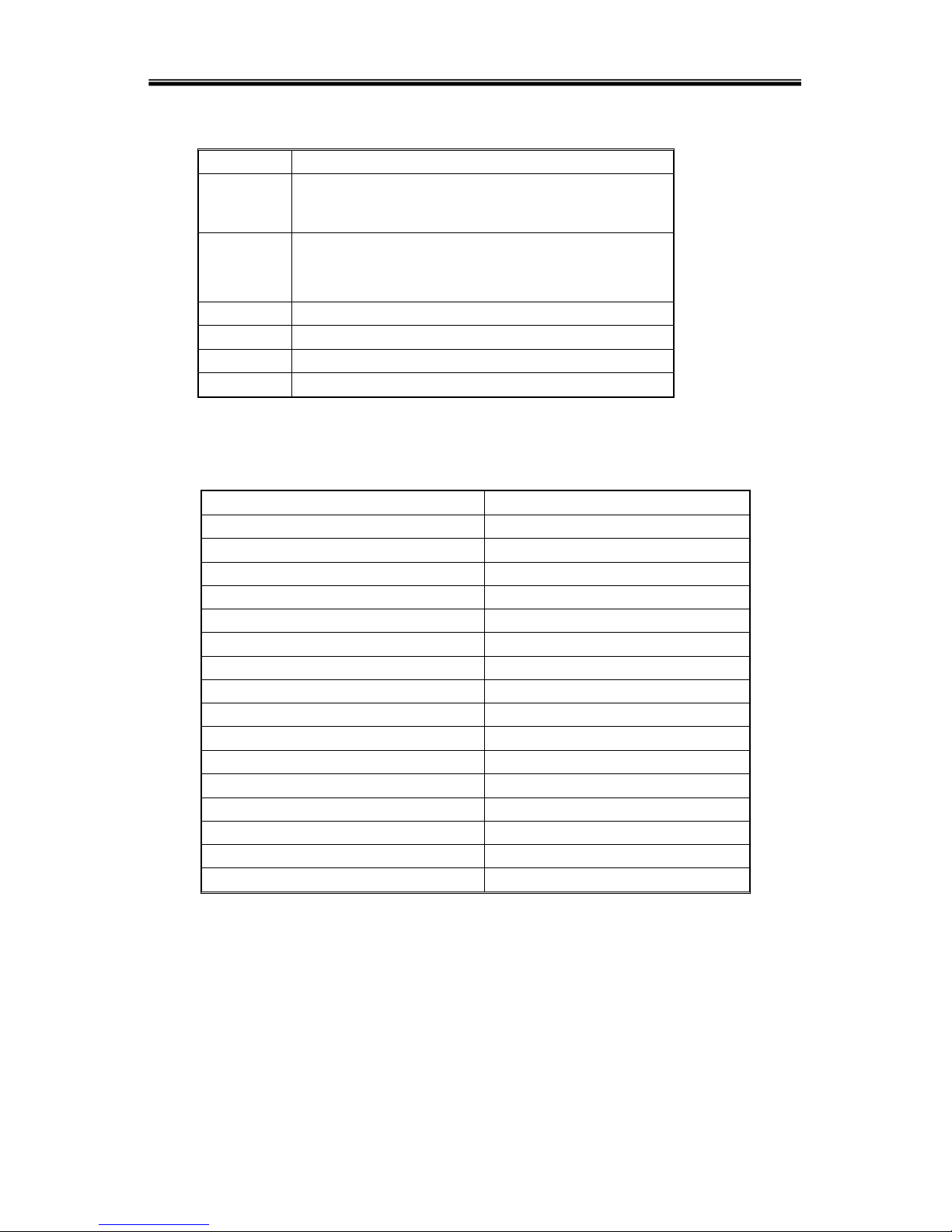
LED indicator definition
1) Fault Indicator(red):On indicates when a fault occurred; Off means no fault
2) Indicator(Green):On means AC is normal, Off means AC is not present,
blinking means voltage is beyond normal range
3) Inverter Indicator(Green):On : when load is powered by inverter, Off : when it
is not working, blinking: when overload
4) Bypass Indicator(Green):On : when UPS is in bypass mode, Off: not in bypass
mode; blinking: when the input is beyond normal range
5) Battery Indicator(Green):On: when UPS is in battery mode, Off : Not in battery
mode; Blinking: when battery voltage is low or battery is not connected
6) Output Indicator(Green):On: when there is output, Off: no output.
LCD display content
1) Running parameters
Input voltage/frequency, output voltage/frequency/current, temperature inside
UPS, battery charging/fully charged, battery voltage.
2)Alarm information ( priority from high to low )
Shutting down, auxiliary power fault, output short circuit, inverter fault, rectifier
fault, over temperature, overload, charger fault, battery fault, ready to shut down,
output fault.
3)Parameter setting
Menu setting, floating /boosting charging setting, battery capacity setting, ID of
parallel UPS, output voltage/frequency level/calibration.
Boosting charging voltage 2.30 to 2.35V per cell floating charging voltage
2.20 to 2.29V per cell
Battery capacity setting includes the above each battery unit, battery
quantity (8 to 10 )*2, parallel group number, low battery voltage alarm value
(EOD ).
Parallel setting
UPS ID setting
LBS setting ( Enable/Disable, Master/Slave)

- 10 -
Button definition
Button
Definition
ON Switch on the inverter by pressing and holding it for
1s when the UPS is off
OFF Switch off the inverter output by pressing and holding
it for 1s when the UPS is on, load will be powered by
bypass output if the bypass is normal
ENT
Confirm the operation
ESC
cancel to up menu
◀
Turn to another menu or parameter
▶Turn to another menu or parameter
UPS Messages reference table
Explain Content
Initialization
CurState: Init
No export No-Out
At bypass Bypass
Rectifier working Mains
Battery invert Battery
Battery testing
Testing
Starting
Startin
ECO mode
CurState : ECO
EPO mode
CurState: EPO
UPS maintaining
CurState: M-Byp
UPS fault
CurState:Fault
Battery float charging Battery Charging
Battery Boost charging Battery Boost
Inverter working or no Inverter ON/ Inverter OFF
Master of UPS Inver Master
Maintenance switch close or open
SWMB ON/ SWMB OFF

- 11 -
1.5.3 Display instruction
1) The main interface below comes out when the power is connected or the system is in
cold start. See Fig1
Fig.1:Main interface
2) Press any key, it will change to the basic status interface , see Fig2 below
Fig.2:Basic status interface
3) Press the ◀or ▶button, it will change to main menu, see Fig3,
Fig.3:Main menu
4) An arrow icon will come out on the LCD when pressing the ENT, then, the data info,
status info, setting info, command control can be selected by pressing the right or left
arrow button, and checking the details by pressing
5) Select and confirm the data info to be viewed in detail. It contains the details of the
AC input /output , inverter, battery , BUS, parallel , temperature. See Fig 4~Fig 12
below.
Fig.4:MAIN INPUT INFO Fig.5:OUTPUT INFO Fig.6:OUTPUT INFO
YDC9310
10KVA
MODE:On-Line
Volt:AN BN CN
Vin: 220 219 221
Vout:220
FIGURE
STATUS
SETTING
COMMAND
Figure
Mains
A:225.9 B:224.8
C:225.5
Figure
Output
220.0V 0.0A
50.0HZ Load: 0%
Figure
Output
0KW PAK: 0
0KVA

- 12 -
Fig.7:INVERT INFO Fig.8:BATTERY INFO Fig.9 BATTERY INFO
Fig.10:BUS INFO
Fig.11:PARALLEL INFO
Fig.12:TEMPERATURE
INFO
6) Select and confirm the status info to be viewed in detail, including status information,
alarm information, code, power rating, version. See Fig 13~Fig 19
Fig.13:main menu Fig.14:main menu
Fig.15:status info Fig.16:Alarm info Fig.17:type info
Fig18:code info Fig19:version info
Figure
INVERT
220.0V
50.0HZ
Figure
BUS VOLT
-390V +390V
Figure
PARALLEL
ID:01
STATUS
State
Alarm & Fault
Rated POWER
STATUS
Rated POWER
Code
Version
STATUS
Status
Main supply
MB Switch close
STATUS
Alarm
STATUS
Rate power
MechInfo: 0101
Rated: 10KVA
STATUS
Code/Status
01 0x00
02 0x000000
STATUS
Version
LCD Ver. D000B001
DSP Ver. D000B001
Figure
Temperature
00℃
Figure
PBATT Discharge
0V 0.0A
Figure
NBATT
0V 0.0A

- 13 -
7) Select and confirm setting menu , setting information will be displayed on the screen,
which includes client setting, system setting, parallel setting, battery setting, correct
setting.
Fig.20:setting menu Fig.21:setting menu
Select and confirm client setting ,then see Fig. 22.
Fig.22:User setting information
Select and confirm system setting menu ,then see Fig23~Fig28
Fig.23:system setting Fig.24:system setting Fig.25:system setting
Fig.26:System setting Fig.27:System setting Fig.28:System setting
Setting
User set
System set
Parallel set
Setting
Battery Set
Setting
User Set
BL. ON
BackLight 2
Setting
System set
V-level 220V
F-level 50HZ
Setting
System Set
Auto Enable
F-Range 5%
Setting
System Set
V-Upper 15%
V-Lower -45%
Setting
System Set
V-Fine 0%
SW Times 9
Setting
System Set
POWER Enable
Buzzer Disable
Setting
System Set
Mode On-Line
POWER Enable

- 14 -
Select and confirm parallel menu,then see Fig.29~Fig.30
Fig.29:Parallel setting Fig.30:Parallel setting
Setting battery see Fig. 31~Fig. 34
Fig.31:battery setting Fig.32:battery setting Fig.33:battery setting
Fig.34 Battery setting
Control operation see Fig.35~Fig.40
Fig.35:control menu Fig.36:control menu
Fig.37 Battery self-test Fig.38 stop battery testing Fig.39 Turn on/off delay
Fig.40 Battery
capacity self-test
Setting
Parallel Set
ID 1
P-Amount 1
Setting
Parallel Set
P-Redund 0
LBS NO LBS
Setting
Battery Set
EOD 1.60
Batt Num 10
Setting
Battery Set
Batt-G 1
Batt-C 7
Setting
Battery Set
Boost 2.30
Float 2.20
Setting
Battery Set
Boost Enable
Command
Battery Test
Turn On Delay
Batt.Cap.Test
Command
For: 1sec
Ent: sure
Esc: cancel
Command
Battery Test
Turn Off Delay
Batt.Cap.Test
Command
STOP Testing
Ent: sure
Esc: cancel
Command
After: 1sec
Ent: sure
Esc: cancel
Command
Batt. Cap.Test
Ent: sure
Esc: cancel

- 15 -
8)Warning message see Fig.41~Fig.46
Fig.41 no echo for setting Fig.42 error for setting Fig.43 switch delay
Fig.44 overload due to
shutdown Fig.45 no output due to
shutdown Fig.46 switch times
Warning!
Set no Echo:31
Warning!
Set Error:31
Warning!
Interrupt
switch prompt
Sure:Ent No:ESC
Warning!
Off will cause
sys.Overload
Sure:Ent No:ESC
Warning!
Off will cause
output fail
Sure:Ent No:ESC
Warning!
Switch Limited
Sure:Ent

- 16 -
1.5.4 Rear panel instruction
Fig.1-4 YDC9310H/S Rear Instruction
1) AC input
2) Maintenance bypass switch (covered)
3) Handle
4) Output
5) Input
6) Dry contact
7) RS232
8) RS485
9) Intelligent slot
10) Parallel slot
11) External battery connector

- 17 -
Fig.1-5 YDC9315/YDC9320 Rear Instruction
1) Input
2) Output
3) AC input
4) Maintenance bypass switch
5) Dry contact
6) RS232
7) RS485
8) Intelligent slot
9) Parallel slot
10) External battery connector

- 18 -
2 Installations
2.1 Unpack checking
1) Don’t lean the UPS when moving it out from the packaging.
2) Check the appearance to see if the UPS is damaged during the transport, do not
switch on the UPS if any damaged found and please contact the dealer.
3) Check the accessories according to the packing list and contact the dealer if
found any parts missing.
2.2 Installation procedure
2.2.1 Installation note
Put the UPS at flat place next to the equipment.
Keep UPS at least 20cm from wall or equipment or other object. Don’t block the
ventilation holes of the UPS front panel and bottom part, so as to keep the
ventilation in good conditions, avoid temperature of components inside getting high.
Keep the UPS away from high temperature, water, flammable gas, erosive gas, dust,
direct sunlight, explosive things
Don't lay the UPS outdoor
3P 125A/400V circuit breaker is required at the input and battery and 2P 125A/400V
is required at the output.
PDU is required to connect to the UPS output so as to weaken the affection between
loads
In order to fix the UPS, please lock its wheels by shifting the sheet on each wheel.
RCD load like computer ,linear load and small inductive load can be connected with
the UPS. Please contact dealer if other types of loads is required to connect.
For the sake of user and equipments, please betake correct power configuration.
Fig.2-1a Correct power configuration

- 19 -
Fig.2-1b Wrong power configuration
2.2.2 Installation
External battery connection (for extended model only )
1) Make sure battery quantity complies with the specs. Measure the voltage of
battery bank after finishing connection and the battery voltage should be around
240VDC. Don’t mix batteries with different capacity, manufacturers and don’t mix
brand new and old batteries, either.
2) The breaker onto battery cabinet should be off.
3) Take out the connection box and remove the cover of terminals, use multi-meter
to make sure there is no DC voltage at the battery terminals of UPS.
4) Connect battery pole with positive pole, negative pole and common pole to
battery connecter(BAT+,BATN,BAT-), don’t reverse battery connection.
CAUTION
It is recommended to connect or replace battery after switching off the
system; don’t reverse battery connection when doing battery hot-swapping.
N
L
N
C
B
A
Fig.2-2a YDC9310S External battery connection

- 20 -
BAT-
BATN
BAT+
L
N
N
C
B
A
BAT+(8/9/10)
BAT-(8/9/10)
Fig.2-2b YDC9310H External battery connection
BAT+(8/9/10)
BAT-(8/9/10)
BAT-
BATN
BAT+
L
N
N
C
B
A
Fig.2-2c YDC9315/9320 External battery connection
Table of contents
Other KStar UPS manuals

KStar
KStar UDC9101S One User manual

KStar
KStar YDC9300-RT Series User manual

KStar
KStar HPM3340 200k User manual

KStar
KStar GP800 User manual

KStar
KStar 1K User manual

KStar
KStar 600 User manual

KStar
KStar UDC9100 Series User manual

KStar
KStar UDC9101RTS User manual

KStar
KStar YDC9300-B User manual

KStar
KStar 600 User manual

KStar
KStar YDC9300-RT Series User manual

KStar
KStar HIP3300E User manual

KStar
KStar YMK3300 Series User manual

KStar
KStar YDC9300-RT Series Quick start guide

KStar
KStar 6kVA User manual

KStar
KStar MEMO PLUS RT II (MP9100RTII-0.9) 1-3K User manual

KStar
KStar YMK3300-200k User manual

KStar
KStar 6K-H User manual