Gtec ZP120N User manual

USERMANUAL
ZP120N10-20kVA 3phases/1phase
Uninterruptiblepower supply
CONTENT:
1. Safety...........................................................................................................1
1.1 Installation..............................................................................................1
1.2 Operation...............................................................................................2
1.3 Maintenance, Servicing and Faults........................................................3
1.4 Transport................................................................................................4
1.5 Storage...................................................................................................4
1.6 Standards...............................................................................................5
2. Description of Commonly UsedSymbols................................................6
3. Introduction.................................................................................................7
3.1 System and Model Description..............................................................7
3.2 Product Specification and Performance...............................................10
4. Installation.................................................................................................13
4.1 Unpacking and Inspection....................................................................13
4.2 Input and Output PowerCordsand ProtectiveEarth Ground
Installation..................................................................................................16
4.3 Operating Procedure forConnecting with The External Battery..........21
5. Operation...................................................................................................23
5.1 DisplayPanel.......................................................................................23
5.2 Operating Mode...................................................................................27
5.3 Turning On andTurning Off UPS.........................................................29
5.4 LCD Operation.....................................................................................31
6. Special function........................................................................................40
6.1 HEFunction.........................................................................................40

6.2 Converter Function..............................................................................40
6.3 Parallel Function..................................................................................41
6.4 tower 3/1 10KOptionalDesign of Charger Current.............................47
6.5 Backfeed Protection.............................................................................48
7. Trouble Shooting......................................................................................51
7.1 Trouble Shooting According ToWarning Indication.............................51
7.2 Trouble Shooting According To Fault Indication...................................53
7.3 Trouble Shooting In Else Cases...........................................................54
8.BatteryMaintenance, Replacement and Disposal.................................56
8.1 Maintenance.........................................................................................56
8.2 Replacement and Disposal of Batteries...............................................57
9. Communication Port................................................................................60
9.1 RS232&USBInterface.........................................................................60
9.2 Intelligent Slot.......................................................................................60
9.3 AS400 Interface (Option).....................................................................60
10. Software..................................................................................................62
Free Software Download – WinPower.......................................................62
1
1. Safety
Please readcarefullythe following usermanual and the safety
instructions before installing the unit orusing theunit!
1.1 Installation
Condensationmayoccurifthe UPSismoveddirectly froma
coldto awarmenvironment.TheUPS mustbe absolutelydry
beforebeing installed.Pleaseallowanacclimatization time of
atleast twohours.
Donot install theUPS nearwaterorindampenvironment.
Do not install theUPS whereitwould beexposedtodirect
sunlightor near heat.
Donotblockventilationopenings inthe UPS’s housing.
Do notconnectappliancesor items ofequipment which would
overload theUPS (e.g.laserprinters,etc) to theUPS output.
Place cablesinsuchaway that no onecan step onortripover
them.
UPShasprovidedearthedterminal, in thefinal installed
system configuration,equipotentialearth bonding tothe
externalUPS battery cabinets.
An integralsingle emergency switchingdevice whichprevents
furthersupply totheloadbytheUPS inany mode of operation
should be provided inthe buildingwiringinstallation.

2
An appropriate disconnectdeviceasshort-circuitbackup
protectionshould beprovidedinthebuildingwiring
installation.
Forthree-phaseequipmentconnectiontoan ITpowersystem,
afour-poledevicewhich disconnectall phaseconductors and
the neutralconductorshouldbeprovidedin thebuildingwiring
installation.
This is permanentlyconnectedequipment, it mustbe installed
by qualifiedmaintenance personnel.
Earthconnectionessential beforeconnectingto thebuilding
wiringterminal.
1.2 Operation
Donotdisconnecttheearth conductorcableontheUPSor the
buildingwiringterminalsinanytimesincethis wouldcancel
the protectiveearthingof theUPS system andof allconnected
loads.
The UPSoutput terminal block may beelectricallylived even if
the UPS system is not connected to the building wiring
terminal.
Inorder to fullydisconnecttheUPS, turntheM1/M2/N input
breakerinthe“OFF”position ( for tower 3/110k-20k), turn the
R/S/T/N input switchinthe“OFF” position (fortower 3/1
10K-31Cmodel), then disconnect the mainslead.
Ensurethat noliquidorotherforeign objectscanenter the
UPS.
3
1.3 Maintenance, servicing and faults
The UPS operateswith hazardousvoltages.Repairsshouldbe
carriedout onlyby qualified maintenancepersonnel.
Caution-riskof electricshock.Evenaftertheunitis
disconnectedfrom the mainspower supply(building wiring
terminal), componentsinsidethe UPSarestillconnectedtothe
batterywhich are potentially dangerous.
Beforecarryingout any kind of serviceand/ormaintenance,
pleasedisconnectthe batteries.Verifythatnocurrentis
present and nohazardousvoltage existsinthecapacitoror
BUS capacitorterminals.
Batteries mustbereplaced onlyby qualified personnel.
Caution-riskof electric shock.Thebatterycircuitisnot
isolated from theinputvoltage. Hazardousvoltages mayoccur
betweenthebattery terminalsand theground.Verifythat no
voltageispresent before servicing!
Batterieshaveahighshort-circuit currentandposeariskof
shock. Takeall precautionarymeasuresspecifiedbelowand
any othermeasuresnecessarywhen working withbatteries:
removeall jewellery,wristwatches, rings and other metal
objects
use only tools withinsulated grips and handles.
Whenchangingbatteries,replacewith thesamequantity and
the same typeofbatteries.

4
Donotattempttodisposeofbatteriesby burningthem.It
couldcauseexplosion.
Donot openor destroybatteries.Effluentelectrolytecan cause
injury to the skin andeyes. It maybetoxic.
Pleasereplacethefuse onlyby afuseofthe sametypeand of
the same amperage inordertoavoidfire hazards.
DonotdismantletheUPS,except thequalifiedmaintenance
personnel.
1.4 Transport
Pleasetransport theUPSonlyintheoriginalpackaging(to
protect against shockand impact).
1.5 Storage
TheUPS mustbestockpiledintheroom whereitis ventilated
and dry.
5
1.6 Standards
* Safety
IEC/EN 62040-1
* EMI
ConductedEmission.................:IEC/EN62040-2 CategoryC3
Radiated Emission...................:IEC/EN62040-2CategoryC3
*EMS
ESD........................................:IEC/EN 61000-4-2Level3
RS..........................................:IEC/EN61000-4-3 Level3
EFT.........................................:IEC/EN61000-4-4 Level4
SURGE....................................:IEC/EN61000-4-5 Level4
Low FrequencySignals.............:IEC/EN61000-2-2
Warning: Thisisaproduct forcommercialandindustrialapplication
in thesecond environment-installation restrictions or additional
measures may be neededtoprevent disturbances.

6
2. DescriptionofCommonly UsedSymbols
Someor allof the following symbolsmay be usedinthismanual. Itis
advisabletofamiliarizeyourself with them and understandtheir
meaning:
7
3. Introduction
3.1 System andmodel description
ThisOnlineSeriesisan uninterruptiblepower supplyincorporating
double-conversiontechnology.Itprovidesperfectprotection
specificallyfor computerequipment, communicationsystemsto
computerized instruments.
Itstrueonlinedouble-conversiondesigneliminatesallmainspower
disturbances. Arectifierconvertsthealternatingcurrentfromthe
utility powertodirect current. This direct current powerstheinverter.
Onthebasis of thisDC voltage, theinvertergenerates apure
sinusoidalACvoltage,whichis constantlypoweringthe loads.
Computersand PeripheralsarethuspoweredentirelybytheUPS. In
the eventofpower failure, themaintenance-free batteries power the
inverter.
Thismanualis applicableto thetower 3/1 10k-20Kmodelsandtower
3/110K-31Cmodel.
The tower3-phaseseriesUPSprovidingoutstandingperformance
and reliability, the UPS’suniquebenefits include:
lOnline UPS designwithpuresinewaveoutput.
lTrueonline double-conversion technologywith highpower density,
utilityfrequency independence, and generatorcompatibility.
lOverallhighefficiency > 93%, saving theoperatingcost.
lTruethree-phasepowerfactorcorrection andhighinputpower
factor(PF>0.99).Savetheinstallationcost andreducethe
pollution backfeed intoupstream powersystem.

8
lHigh output power factor (0.9), toadapt more typeload.
lIntelligentBatteryManagement technologythat usesadvanced
batterymanagement toincreasebatteryservice life,optimize
recharge time.
lSelectableHigh Efficiency mode(ECOmode) orCVCFmode
operation.
lComboinput (single phase or three phase) autodetection
lBack-feed protection
lStart-on-battery capability forpoweringuptheUPSevenifutility
power isnot available.
lStandard communicationoptions:oneRS-232communicationport,
one USB communicationport.
lOptionalconnectivity cardswith enhanced communication
capabilities.
lRemoteshutdown controlthrough theRemote Power-off(RPO)
port.
lFortower 3/1 10k-20k, Maintenancesaresimplified byallowingthe
safereplacement of batteries withoutpowering down the UPS.But
tower 3/110K-31Cmodel haveno this function.
lN+X parallel redundancytoincreasethe reliability andflexibility.
The maxparallelnumberis 4.
lUser-friendlyLCD displayand LED indicators.
lFortower3/110k-20k, easilybattery exchange orextensionand
availableto extend thebackuptime. But tower 3/1 10K-31Cmodel
haveno this function.
The appearanceof tower 3-phase series
ReferstoFig. 3-1
9
TOWER 3/110KvaREARVIEW
TOWER 3/120KvaREARVIEW

10
Tower 3/110K-31CREAR VIEW
Fig. 3-1 therearview of the tower3-phase seriesUPS
3.2 Product Specification and Performance
1) General Specification
Model 10KVA20KVA10K-31C
Power Rating 10KVA/9KW20KVA/18KW10KVA/9KW
Frequency (Hz)
50/60
Voltage
(110-276)VAC(Depends on Load Level)
Input
Current
L1/L2/L3:23AMAX
L1/L2/L3:46AMAX
L1/L2/L3:23AMAX
Voltage
288VDC240VDC
Battery
Current
43AMAX 86AMAX 51.8AMAX
ParallelPort
(Optional)
IntelligentSlot
EPO RS232USB
Fan
AS400
InputBreaker
TerminalBlocks
Cover
ExternalBattery
IECConnector
Maintenance and Output
Switch Cover
11
Voltage
200VAC/208VAC/220VAC/230VAC/ 240VAC*
Output
Current
45A/48.1A/45.5A/4
3.5A/41.7A 90A/96.2A/90.9A/8
7.0A/83.3A 45A/48.1A/45.5A/4
3.5A/41.7A
Dimension
(WxDxH) mm 350x650x890 260*550*708
NetWeight(kg)
127 188 85
2) Electrical Performance
Input
Model Voltage Frequency Power Factor
10KVA/20KVA/10K-31C
Three-phase 50/60 Hz±10%
>0.99(@Full load)
*If output voltage be set 200V, output powerwill derating to90% of power
rating
Output
Voltage
Regulation
Power
Factor
Frequency
tolerance. DistortionOverload capacity Current
crestratio
±1% 0.9lag
Synchronized
50/60Hz±10%
inLinemode
(ACmode)
±0.1% of
normal
frequency in
Batterymode
THD<2%
Full load
(Linear
Load)/
<5% for
reference
non-linear
load
100%-110% load
transfers toBypass
mode after5
minutes
110%-130% load
transfers toBypass
mode after1
minutes
130%-150% load
transfers toBypass
mode after 10
second
>150% load
transfers toBypass
mode after2second
3:1

12
3) Operating Environment
Temperature Humidity Altitude Storage temperature
0°C-45°C <95% <1000m -15°C-50°C
Note: if theUPS is installed orused inaplacewherethealtitudeis
abovethan 1000m,theoutputpower mustbederatedin use, please
refertothe following:
Altitude (M)
1000
1500
2000
2500
3000
3500
4000
4500
5000
Maximum
Power 100%
95% 91%
86% 82%
78% 74%
70% 67%
13
4. Installation
The systemmaybeinstalled and wired onlybyqualified
electricians in accordance with applicable safety regulations!
4.1 Unpacking and Inspection
1. Moving to theinstallationsite
The tower3-phase seriesUPS has wheelsmaking it easytomove the
UPStothe installation site afterit hasbeenunpacked. However,if the
receiving area isfarfrom theinstallationsite,we recommendyou to
movetheUPS by usingapalletjackor alifter beforeyou startto
unpack the UPS.
2. Unpackingand inspection
1) At theinstallationsite,theutmostcareshallbe takenwhen
removingthepackaging in order to avoiddamagingthe equipment.
Checkallpackaging materialstoensurethat no itemsare missing.
The shippingpackage contains:
A UPS
A user manual
A communication cable
Parallelport coverplate

14
Removethepackagingfollowingthesequenceillustrated in Fig.4-1 to
Fig.4-4. (onlyfortower3/110k-20k)
Tools kit
Lifter Phillipsscrewdriver
Scissors Wrench
Fig.4-1 Unpacking-step1 Fig.4-2Unpacking-step2
15
The shippingmaterialsarerecyclable. Afterunpacking,
savethem for later use or dispose of them appropriately.
2) Inspect theappearanceoftheUPStosee ifthere is any damage
during transportation.Do not turnontheunitandnotifythecarrier
and dealer immediately if thereisanydamageorlacking ofsome
parts.
Fig. 4-3Unpacking-step3 Fig.4-4 Unpacking-step4

16
4.2 Input andOutput Power Cords andProtective
EarthGround Installation
1. Notesforinstallation
1) The UPSmustbe installed inalocationwithgoodventilation,far
awayfromwater,inflammable gas and corrosive agents.
2) Ensuretheairvents onthefront andrearoftheUPSare not
blocked.Allowat least 0.5mof spaceon each side.
3) Condensationtowaterdropsmay occurif theUPSisunpackedina
verylowtemperatureenvironment.Inthiscaseit isnecessaryto
wait untilthe UPSisfully driedinside outbeforeproceeding
installation and use. Otherwise there arehazards of electricshock.
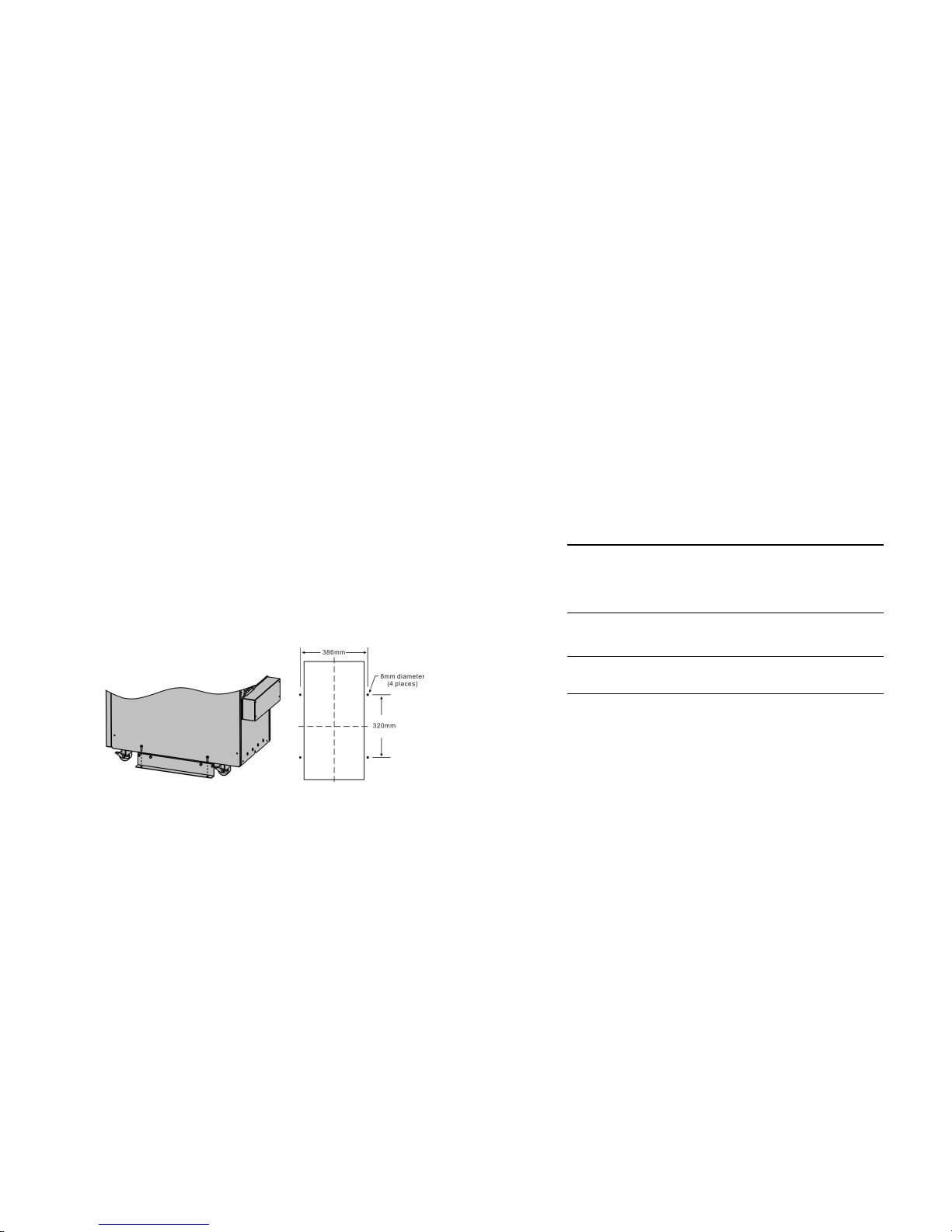
4) Oncetheinstallation iscompleted, thesidemountingbrackets
(usedinshipping)shallbefixedbacktoensurethestabilityofthe
UPS enclosure. Ifimpossible,additional stability can beaddedby
anchoringthemountingbrackets tothe floorwith M8bolts.See Fig.
4-5. (onlyfor tower3/1 10k-20k)
Fig.4-5 Additionalstability
2. Installation
Installationand wiringmustbeperformedinaccordance with the
localelectriccodeand the followinginstructionsbyprofessional
personnel.
17
Forsafety, pleasecut offthe mainspower switch before installation.
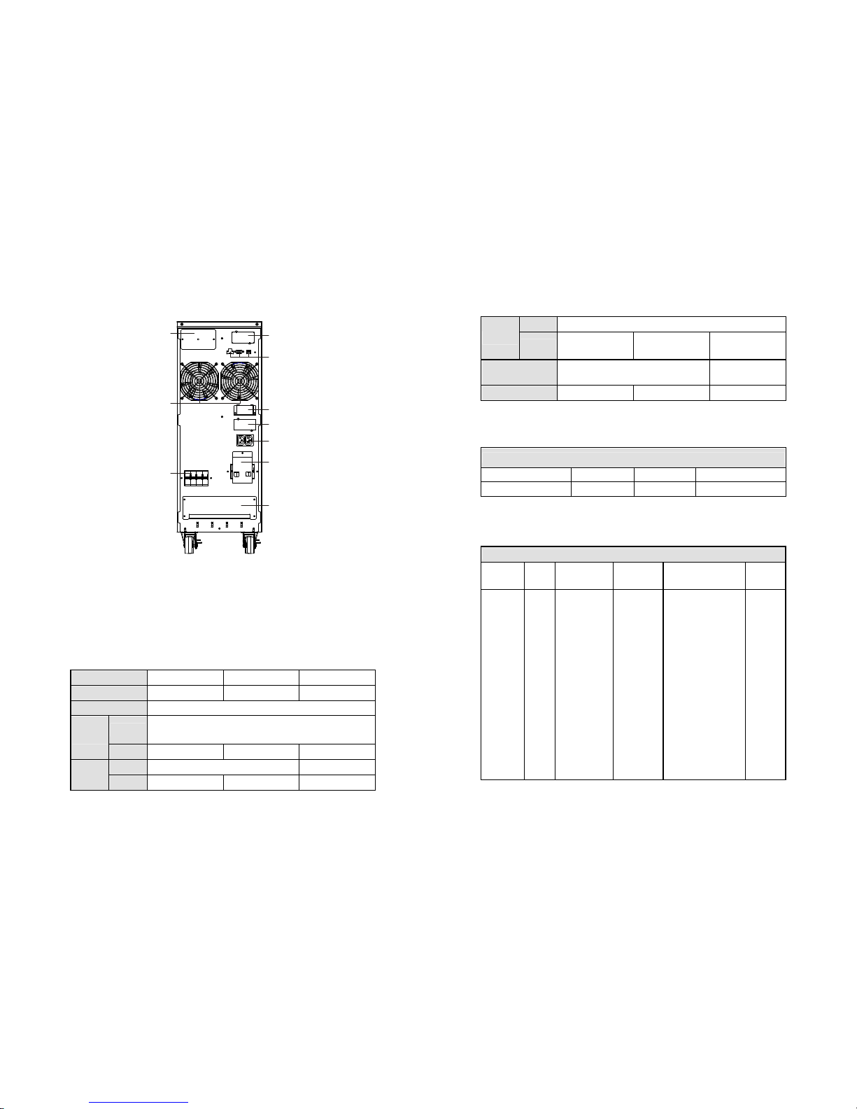
1) Opentheterminalblockcoverlocated ontherearpanelof the
UPS, pleasereferto theappearance diagram.
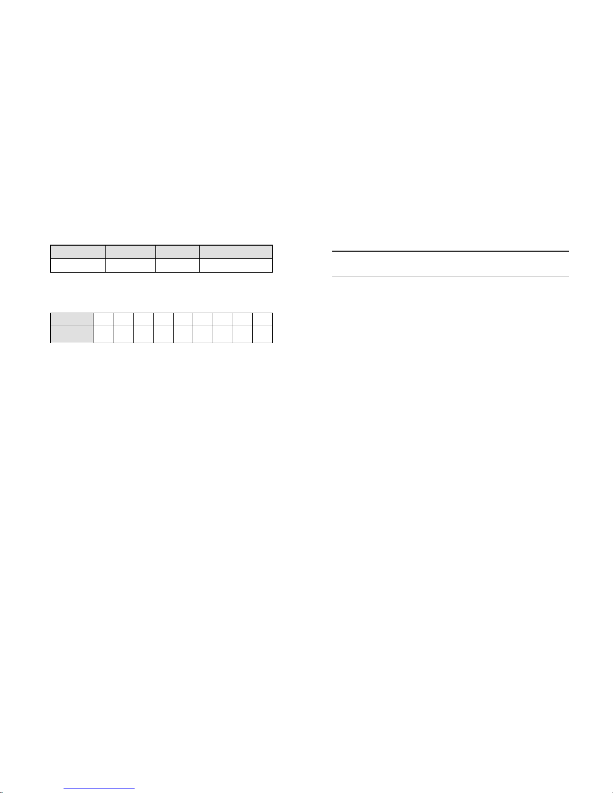
2) Fortower3/110K/10K-31CUPS, itis recommendedtoselectthe
UL1015 8AWG(10mm2)wire orotherinsulatedwirewhich
complieswithAWG Standardforthe UPSinputand output
wirings.
3) Fortower3/1 20K UPS,itis recommended to selectthe UL1015
6AWG(25mm2)wireorotherinsulatedwire whichcomplieswith
AWG Standardfor the UPS inputandoutput wirings.
Note: Do not usethewallreceptacleas the input power source
for theUPS,asits ratedcurrent islessthan theUPS’s
maximum inputcurrent. Otherwisethereceptacle may be
burnedanddestroyed.
4) Connecttheinputandoutput wirestothecorresponding input
and output terminals according to thefollowing diagram.
Note: youmustmakesurethat theinputandoutput wires and
the input and output terminals are connected tightly.
5) The protectiveearth ground wirerefersto thewire connection
between theequipmentwhichconsumeselectric equipment and
thegroundwire.Thewirediameter ofprotectiveearthground
wireshouldbeat leastasabovementionedforeach model and
green wire or greenwirewith yellow ribbon wire isused.
6) Afterhaving completedtheinstallation, makesurethe wiring is
correct.
7) Pleaseinstall the outputbreaker between theoutputterminal
andtheload,andthebreaker should withleakagecurrent
protectivefunctionif necessary.

18
8) ToconnecttheloadwiththeUPS, please turnoffallthe loads
first,thenperformtheconnectionandfinallyturnonthe loads
oneby one.
9) Nomatter the UPS isconnectedto theutilitypower ornot, the
outputof the UPS mayhave electricity. Thepartsinside the unit
maystillhavehazardousvoltageafter turning offthe UPS.To
maketheUPS havenooutput, poweroffthe UPS,andthen
disconnectthe utilitypowersupply.
10) Suggestchargingthe batteriesfor8hours beforeuse.After
connection, turntheM1/M2/N inputbreaker(fortower 3/1
10k-20K), turntheinput switch (fortower 3/110K-31C model) in
the"ON"position, theUPSwillchargethebatteriesautomatically.
YoucanalsousetheUPS immediatelywithoutchargingthe
batteries first,butthebackuptimemaybelessthan the
standardvalue.
11) If itis necessary to connect theinductanceloadsuchasa
monitoror a laser printertothe UPS,thestart-uppower should
beused for calculatingthecapacity oftheUPS,asits start-up
power consumptionistoobig when it isstarted.
Tower 3/110k-20K
19
Tower 3/110K-31Cmodel
Fig.4-6 Input andoutput Terminal Blockwiring diagram
Importantnotes: If the UPS is used insinglemode, JP1 andJP2must
be connected.IftheUPSis usedin parallel mode, the Jumper between
JP1 and JP2 mustbe removed.
Use cable crosssection and protectivedevicespecification
ModelTower 10k Tower 20k
Input L1,L2,L3
Min.conductor crosssection[mm2]
Max.conductor cross section[mm2]
2.5
4
6
10
Input L1,L2,L3 breaker (A) 40A,250VAC60A,250VAC
Input N, M2
Min.conductor crosssection[mm2]
Max.conductor cross section[mm2]
10
13
21
25
Input M2breaker (A) 63A,250VAC100A,250VAC
Input fuse (A) 30A,250VAC50A,690AC
OutputL,N,
Min.conductor crosssection[mm2]
Max.conductor cross section[mm2]
10
13
21
25

20
ExternalBattery Cabinet Positive
Pole(+),Neutralpole,Negative
pole(-),
Min.conductor crosssection[mm2]
Max.conductor cross section[mm2]
10
13
21
25
Line inputBackfeedprotection device A4-pole disconnectiondevice with
100A/250VAC,less than15s break
timeandmin.1.4mm clearance
will be used infinal installation for
backfeedprotectioninlineinput.
M2inputBackfeedprotectiondevice A2-pole disconnectiondevice with
100A/250VAC,less than15s break
timeand min.1.4mm clearance
will be used infinal installation for
backfeedprotectioninlineinput.
Protective Earthing conductor[mm2] Max.13 Max.25
Torquefor fixingaboveterminals (10 1b in) (18 1b in)
Sheet.1 tower 3/1 10KVA/20KVAmodels
Model10k-31C
Input L2,L3
Min.conductor crosssection[mm2]
Max.conductor cross section[mm2]
2.5
4
Input L1,L2,L3,Nswitch (A) 63A,250VAC
Outputswitch(A)/maintain switch(A) 63A,250VAC
Input L1,N
Min.conductor crosssection[mm2]
Max.conductor cross section[mm2]
10
13
Input fuse (A) 30A,250VAC
21
OutputL,N,
Min.conductor crosssection[mm2]
Max.conductor cross section[mm2]
10
13
ExternalBattery Cabinet Positive
Pole(+),Neutralpole,Negative
pole(-),
Min.conductor crosssection[mm2]
Max.conductor cross section[mm2]
10
13
Protective Earthing conductor[mm2] MAX13
Torquefor fixingaboveterminals (10 1b in)
Sheet.2tower3/1 10K-31Cmodel
4.3 Operating ProcedureforConnecting with The
External Battery
1.Fortower3/1 10K-20K, ThenominalDCvoltageofexternalbattery
pack is288VDC.Eachbattery packconsistsof24 piecesof12V
maintenance free batteriesinseries.For tower 3/1 10k-31C model,
thenominalDC voltageof external batterypackis240VDC.Each
batterypack consistsof 20piecesof12Vmaintenance free batteries
in series ,Toachievelongerbackuptime,itispossibleto connect
multi-battery packs,but the principle of “same voltage,same type”
should bestrictly followed.
2.Fortower3/110K-20K,select theUL10158AWG (10mm2)/6AWG
(25mm2)wirerespectivelyorotherinsulated wire which complies
with AWG Standardforthe UPSbattery wirings.The procedureof
installingbattery bankshouldbe compliedwithstrictly.Otherwise
you may encounterthe hazardousofelectric shock.
1) Fortower3/1 seriesif theUPS hasinternalbattery pack, firstof
all, disconnect theinternalbatterypackDCconnectors.

22
tower3/1 20K tower 3/1 10K
Fig. 4-7Disconnectthe internal batterypackDC connectors
2) ADCbreakermust beconnectedbetween theexternalbattery
packandtheUPS.The capacityof breakermust benot lessthan
the data specifiedinthegeneralspecification.
3) Set theexternalbatterypackbreaker in“OFF” positionand
connectthebatteries (24piecesfortower3/1 10K-20K,20
piecesfortower3/1 10k-31C) in series.
4) Fortower3/1 10K-20K,Connecttheexternalbattery packto the
battery terminals.For tower3/110K-31Cmodel,Connectthe
externalbattery pack to the battery andersonconnector.
5) ReconnecttheinternalbatterypackDC connectors, if you had
didstepone.
3.Donot attemptto connectanyloadstotheUPSnow.You should
connectthe inputpowerwireto theright position first. And then set
thebreaker ofthebattery packinthe“ON”position.After that set
theinputbreaker inthe“ON” position. The UPS begins tochargethe
battery packs at the time.
23
5. Operation
5.1 DisplayPanel
The UPShas afour-buttongraphicalLCD with dualcolorbacklight.
Standardback-lightisused to lightupthedisplay with white textand
ablue background.WhentheUPS hasacriticalalarm, thebacklight
changes thetexttodarkamber andthebackgroundtored.Besides
the graphical LCD,theUPS hasfourcolorized LEDstoprovideyou
moreconvenientinfo.
See Figure Below
Fig.5-1 tower 3/1 10k-20K/tower3/1 10K-31COn-line UPS ControlPanel
Table5-1 ControlButtonFunctions

24
TheButton Function Illustration
Power on Whentheunitis no power and has connected
withbattery,press this buttonfor >100ms&<1s
topower on
Turnon Whentheunitis powered onandinBypass
mode,press this buttonfor>1s toturnon
Turnoff Whentheunithas beenturned on, press this
buttonfor >3s toturnoff
Entermain
menu
Whendisplayingdefault UPSstatussummary
screen,press this buttonfor >1s toenter the
mainmenutree
Exit main
menu
Press thisbuttonfor >1s toexitthepresentmenu
todefaultsystemstatus displaymenuwithout
executing a command orchanging a setting
Scroll up Press this buttonfor>100ms&<1s toscroll upthe
menuoption
Scroll down Press this buttonfor>100ms&<1s toscroll down
themenu option
Enternext
menu tree
Press this buttonfor>100ms&<1s toselect the
presentmenuoption, orenter next menu, but do
not change anysetting
Select one
menu option
Press this buttonfor>100ms&<1s toselect the
presentmenuoption, orenter next menu, but do
not change anysetting
Confirmthe
present
setting
Press this buttonfor>1s to confirmthe edited
optionsandchange the setting
Table5-2 LED definition
25
UPS state Normal LED
(Green)
Battery LED
(Yellow)
Bypass LED
(Yellow)
FaultLED
(Red)
Bypass mode
withno output
Bypass mode
withoutput
Turningon △△△△
Linemode
Battery mode
HE mode
Battery test mode △△△△
Fault mode
Warning
Note:
:Lightenedconstantly
:#1△-#4Lightened circularly
:Flashing
:Dependedon the fault/warningstatusorother status
Table5-3 Buzzerdefinition
UPS condition Buzzer status
Fault activeContinuous
Warning active Beep everysecond
Batteryoutput Beep every4seconds,if battery low,buzzer Beep every second
Bypass outputBeep every2 minutes
The UPS providesusefulinformationaboutUPSitself,load status,events,

26
measurements, identification, andsettings throughthe front paneldisplay.
After poweringon,the LCDwilldisplay the“WELCOME” logo forseveral
seconds andthenenter to thedefaultpagewhich shows theUPSstatus
summary.Thedisplayautomaticallyreturnstothe defaultUPS status
summaryscreenwhennobutton hasbeen pressed within 15minutes.
On the UPSstatussummaryscreenit provides the following information:
lStatussummary,including mode and load
lAlarm status,if anyarepresent
Notes: alarm including faultand warninginformation
lBatteryandcharger status,including battery voltage, charger
level and chargerstatus
lRunninginformationincludingparallel UPS and running time
Fig.5-2 ThedefaultLCD display
The moredetailedoperationof LCD isillustratedinthechapterof5.4.
27
5.2 Operating Mode
The different graphic symbolcouldbedisplayed corresponding to current
operatingmode orstatus.
Table5-4 Status SummaryScreens
Status SummaryScreen Description
Fig5-3
Normalmode:
The UPSis operating inNormal mode from
utility power.
Fig5-4
Battery mode:
WhentheUPSis runninginbattery mode, the
buzzer beeps once every 4 seconds.
Fig5-5
Bypasswith output:
The UPSdoes nothavethebackup function
whenitis inbypass mode. Thepowerused by
the load is suppliedfromthe utility power via
internal filter.TheUPSwill beep once every2
minutes inbypass mode.
Fig5-6
Bypasswithoutoutput:
The UPSinbypass mode without output

28
Fig5-7
High Efficiency Mode:
After theUPSis turned on,thepower used by
theload is supplied from theutility power via
internal filterwhile theutility poweris in
normal range, so thehighefficiency could be
gainedintheHEmode. Once themainsis loss
orabnormal, theUPSwould transfer toLine
mode orBatterymode andtheload is
suppliedcontinuously.
1) Thefunctioncould be enabled through
theLCDsettingorthesoftware
(Winpower, etc.).
2) Itis attentionthatthetransfer timeof
UPSoutputfromHE mode tobattery
mode is about10ms.But itis still too
long for some sensitiveload.
Fig5-8
Converter mode
Inconverter mode,theUPSwould free run
withfixed outputfrequency (50Hzor 60Hz).
Once themainsisloss orabnormal, theUPS
would transfertobattery mode andtheload is
suppliedcontinuously.
1) Thefunctioncould be enabled through
theLCDsettingorthesoftware
(Winpower, etc.).
2) Theload should be derated to60%
whenrunninginconvertermode with
single phase input,andthere is no
derating withthree phases input.
Fig5-9
Warning:
Whenthewarningoccurs,it illustrates that
there are someabnormal problemsduringthe
operationofUPS.Normallytheproblemsare
not fatal andtheUPS continues working,but
they should be paidattention to,or theUPS
may fail.
29
Fig5-10
Fault:
Whenthefault occurs, it illustrates that some
fatal problemshappened,theUPSwould
directly cutofftheoutputortransfer to
bypass, andkeep alarming. Thebacklightof
LCD would also turntored.
Fig5-11
Overload:
WhentheUPSis overload, thealarm will beep
twice every second.Someunnecessary loads
should be get rid ofoneby onetodecrease
the loads connected totheUPS.
Fig5-12
Battery Test
UPSis executing a battery test
Fig5-13
Battery fail:
if thebattery statusdetected is“bad battery
detected” or “battery disconnected”,the
symbolof battery failure would be shownand
UPSwould alarm.
5.3 TurningOnandTurning Off UPS
Attention: Please switch offtheconnectedloadsfirstbefore turningon
theUPS, and switchontheloadsone byoneafterthe UPSisturned on.
Switch offallof theconnectedloads before turning off the UPS.

30
5.3.1Turning OnUPS With Utility
1) Check that power supply connectioniscorrect. Check thebreaker
of batterypackis in“ON”position (thisstep onlyfor longbackup
time model).
2) Fortower3/110k-20k set inputbreaker(M1&M2)in“ON”position,
for tower3/110K-31Cmodel set input4P-switch in “ON”
position.Atthistime thefanbeginstorotate. LCDwillshow
“WELCOME” logo. Then LCD will showthesystem statussummary
screen after UPS finishing self-test.
3) Bypressing button continuously for more than1second,the
buzzer will beep1s,UPS startsto turnon.
4) Afew secondslater,theUPS turnsinto Linemode.Iftheutility
power is abnormal,theUPS will transfer to Batterymode without
output interruption ofthe UPS.
5.3.2Turning OnUPS Without Utility
1) Check thebreakerofthebattery packisin“ON” position (this step
only forlongbackup time model).
2) By pressing button continuouslyformorethan100ms,the UPS
wouldbe powered on.Atthistimethefan beginstorotate, LCD
will showthe “WELCOME” logo.ThenLCDwill showthe default
UPS statussummaryscreen afterUPSfinishingself-test.
3) Bypressing button continuously for more than1second,the
buzzer will beep1s,UPS startsto turnon.
4) Afew seconds later,theUPS turns into Batterymode. If the utility
power comesback,theUPS will transfertoLine modewithout
output interruption ofthe UPS.
5.3.3Turning Off UPS With Utility
1) Toturnofftheinverter ofUPS bypressing button continuously
for morethan 3seconds and the buzzer will beep 3s.TheUPSwill
turn into Bypass modeatonce.
31
2) Whencompletingtheabove action, UPSoutputvoltageis still
present.Inorderto cutoffthe UPSoutput,simply cut off theutility
powersupply. Afew secondslater, LCD display shutsdown andno
output voltage isavailable fromtheUPSoutputterminal.
5.3.4Turning Off UPS Without Utility
1) TopowerofftheUPSbypressing buttoncontinuouslyformore
than3second,andthebuzzerwillbeep3s.The UPSwillcut offthe
outputatonce.
2) Afew secondslater,LCDshutsdown and novoltageisavailable
fromtheUPSoutput.
5.4 LCDOperation
Except thedefaultUPSstatussummary screen, the usercouldget
moreusefulinformation aboutUPScurrentstatus, detailed various
measurements,oldevents whichever occurred, UPSown
identification, andcould changethesettingsto fittheuserown
requirements,optimizethefunctionofUPS.
5.4.1TheMainMenu
InthedefaultUPSstatussummary screen, whenpressing or
<1s, the detailed information aboutalarm, the system status,battery
would beshown.
Inthedefault UPSstatussummaryscreen, when pressing >1s,
the displaywould enter main menu tree.
The main menu tree includessixbranches: UPSstatus menu,event
logmenu,measurementmenu,controlmenu, identificationmenu,
setting menu.

32
Fig.5-14Mainmenutree
33
5.4.2TheUPS StatusMenu
Bypressing onthemenuof “UPS status”,thedisplaywouldenter
the nextUPS status menutree.
The content of UPS statusmenu tree issame as the defaultUPS status
summarymenu.
Bypressing >1s,thedisplay wouldreturnthe lastmainmenu
tree.
The detailinformation about “UPSstatus”, pleasesee Fig5-14
5.4.3TheEvent LogMenu
Bypressing onthemenuof “Event log”,thedisplaywould enter
the next eventmenutree.
All the oldevent,alarm andfaulthavebeenrecordedhere. The
information includes theillustration,theevent code,and the operating
timeof UPSwhen theeventhappened.Bypress or <1s,all
the event could be displayed one by one.
The max numberof recordis30, when thenumberis largerthan30,
the oldest one wouldbe changed to thenewest information.
Bypressing >1s,thedisplay wouldreturnthe lastmainmenu
tree.

34
Fig.5-15Event menutree
5.4.4TheMeasurement Menu
Bypressing onthemenuof “Measurement”,the display would
enterthe next measurementmenu tree.
Alotofdetailedusefulinformationcould bechecked here, Ex. the
outputvoltageandfrequency,theoutputcurrent, theload capacity,
the input voltage and frequency, etc.
Bypressing >1s,thedisplay wouldreturnthe lastmainmenu
tree.
35
Fig.5-16 Measurementmenu tree
5.4.5TheControl Menu
Bypressing onthemenuof“Control”,thedisplaywouldenterthe
nextcontrol menutree.
1) Start BatteryTest:isonecommandtocontroltheUPStodo the
batterytest.
2) ClearEPO status:onceEPO statusisenabled,theUPSoutput
wouldbecut off.Torecovertonormalstatus,firstEPO connector
shouldbeclosed,andenterthis menutoclearEPO status,then
UPSwouldstop alarmandrecovertoBypassmodel.AndUPS
needsbeturned on by manualoperation.
3) Reset Faultstatus:whenfaultoccurs,UPSwouldkeepin Fault
modeandalarm.Torecoverto normalstatus,enterthismenuto
reset errorstatus,thenUPS would stopalarmandrecover to
Bypass mode. Andthereason of faultshouldbecheckedand
deleted before UPS is turned onagain by manualoperation.

36
4) Restorefactory settings:allthesettings would berecover to
defaultfactory settings. Itcould only be doneinBypass mode.
Fig.5-17Controlmenutree
37
5.4.6TheIdentification Menu
Bypress on themenu of “Identification”,thedisplaywould enter
the nextidentificationmenu tree.
The identification informationincludesUPSserialnumber,firmware
serialnumber,model type, wouldbeshownhere.
Bypress >1s,the displaywouldreturn the last main menu tree.
Fig.5-18Identification menutree
5.4.7TheSettingMenu
Pleasecontactyourlocaldistributorfor furtherinformationbefore
using thesettings.Some settingswouldchangethespecification,and
some settings wouldenableor disablesome functions. Theunsuitable
optionset by usermayresult inpotential failuresorprotecting
Other manuals for ZP120N
1
Table of contents
Other Gtec UPS manuals