meibes UK User guide

Effiziente Energietechnik
Meibes System-Technik GmbH
Ringstraße 18 · D-04827 Gerichshain · Tel. +49(0) 3 42 92 7 13-0 · Fax 7 13-808
Anleitung für Montage und Betrieb
PR 24002.226 27-09-2017 Technische Änderungen vorbehalten
Pumpengruppen Edition 8
DE
Pump groups Edition 8
Instructions for installation and operation GB
Groupe de pompe édition 8
Instructions de montage et de fonctionnement FR
Grupos de bombeo Edition 8
Instrucciones de montaje y servicio ES
Pompgroepen editie 8
Montage- en gebruikshandleiding NL
Gruppi pompa edizione 8
Istruzioni per il montaggio e l'utilizzo IT
Grupy pompowe Edition 8
Instrukcja montażu i obsługi PL
Skupiny čerpadel Edition 8
Návod k montáži a provozu CZ
Насосные группы редакция 8
Руководство по монтажу и эксплуатации RU
Skupiny čerpadiel vydanie 8
Návod na montáž a prevádzku SK
Szivattyúcsoportok kiadás 8
Szerelési és üzemeltetési utasítás HU
Сорап топтары, 8-нұсқа
Монтаждау және пайдалану бойынша нұсқаулық KK
Konstantwert-
regelset
Trennsystem
UK (-Z) MK MK-Z

2
Inhalt
1. Grundlagen 3
1.1 Sicherheitshinweise 3
1.2 Bestimmungsgemäßer Einsatz: 3
1.3 Funktionen 4
2. Montage und Betrieb 5
2.1 Montage 5
2.1.1 Allgemeine Montagehinweise 5
2.1.2 Allgemeine Montagehinweise zum Schutz der Pumpe 5
2.1.3 Montage an Heizkreisverteiler 5
2.1.4 Montage an einer Wand 5
2.1.5 Montage Wärmemengenzähler (nur UK-Z und MK-Z) 6
2.2 Hydraulischer Anschluss 6
2.3 Elektrischer Anschluss 7
2.4 Inbetriebnahme 7
2.4.1 Kugelhahnstellungen / Rückflussverhinderer (Schwerkraftbremse) 7
2.4.2 Mischer 8
2.4.3 Stellantrieb montieren 8
2.5 Inbetriebnahme 9
2.6 Betrieb 9
2.7 Wartung 9

3
1. Grundlagen
1.1 Sicherheitshinweise
Bitte befolgen Sie diese Sicherheitshinweise genau, um Gefahren und Schäden für Menschen und Sachwerte auszuschließen. Die Monta-
ge, Erstinbetriebnahme, Inspektion, Wartung und Instandsetzung müssen von einer zugelassenen Fachfirma ausgeführt werden. Machen
Sie sich vor Arbeitsbeginn mit allen Teilen und deren Handhabung vertraut. Beachten Sie die gültigen Unfallverhütungsvorschriften,
Umweltvorschriften und gesetzlichen Regeln für die Montage, Installation und den Betrieb. Des weiteren die relevanten einschlägigen
Richtlinien der DIN, EN, DVGW, VDI und VDE sowie alle aktuellen relevanten länderspezifischen Normen, Gesetze und Richtlinien.
Arbeiten an der Anlage: Anlage spannungsfrei schalten und auf Spannungsfreiheit kontrollieren (z.B. an der separaten Sicherung
oder einem Hauptschalter). Anlage gegen Wiedereinschalten sichern. (Bei Brennstoff Gas den Gasabsperrhahn schließen und gegen
unbeabsichtigtes Öffnen sichern). Instandsetzungsarbeiten an Bauteilen mit Sicherheitstechnischer Funktion sind unzulässig. Der
Montageort muss trocken und frostsicher sein. Gefährdungen durch angrenzende Bauteile sind zu vermeiden. Der freie Zugang muss
sichergestellt sein.
1.2 Bestimmungsgemäßer Einsatz
Die in der nachfolgenden Anleitung benannten Bauteile sind für den Einsatz in Heizungsanlagen nach DIN EN 12828 bestimmt. Der Betrieb
mit verunreinigtem Wärmeträger ist unzulässig-dazu zählen u.a. Fremdpartikel, härtebildendende Stoffe und Sauerstoff. Die Stromversor-
gung der Umwälzpumpe wird bedarfsorientiert von einer externen Regelung übernommen – ebenso bei Bedarf die Ansteuerung für die
Drehzahlregelung. Ein Rückflussverhinderer, meist in einen Kugelhahn integriert und manuell aufstellbar, sperrt die Strömung entgegen der
gewollten Richtung. Der Auslieferungszustand umfasst Material für die Integration in Systeme mit passendem Verteiler. Zubehör ermöglicht
den Einsatz als Einzelkomponente
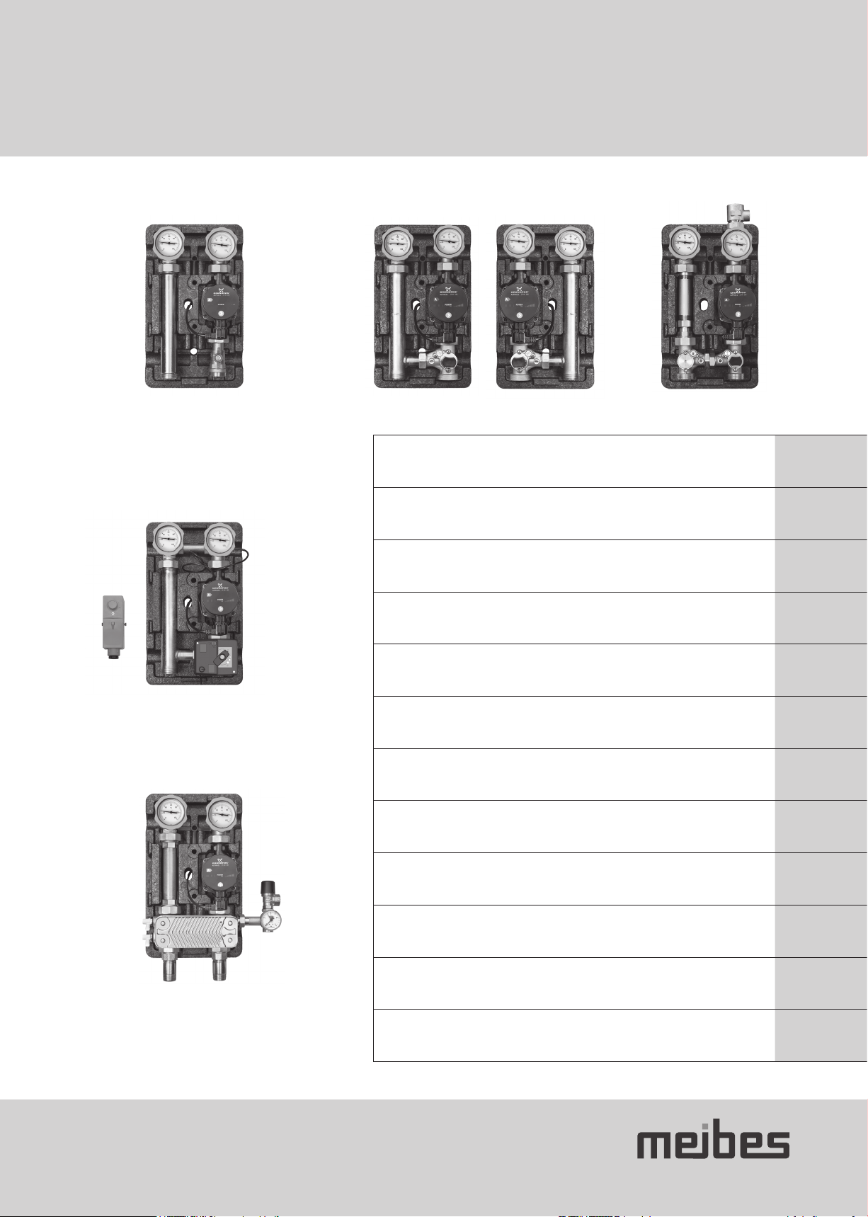
Pumpengruppen UK, UK-Z
Die Pumpengruppen UK und UK-Z sind konzipiert, Heizungswasser in ungemischten Heizkreisen umzuwälzen. Typische Anwendungen fin-
den sich bei Radiatorenheizung und Speicherladung.
Pumpengruppen MK, MK-Z
Die Pumpengruppen MK und MK-Z sind konzipiert, Heizungswasser in gemischten Heizkreisen umzuwälzen. Typische Anwendungen finden
sich bei Fußboden- und Wandheizungen. Ein Stellantrieb für den Mischer ist als Zubehör in verschiedenen Varianten zu ergänzen.
Konstantwertregelset
Einsatz wie MK, aber mit vormontiertem Stellantrieb mit Festwertregelung. Typische Anwendungen finden sich bei Heizsystem mit Tempe-
raturbegrenzung zum Schutz der Anlagenteile oder mit nachgeschalteter Regelung der bedarfsgerechten Wärmeversorgung.
Trennsystem
Einsatz wie UK, aber inklusive Plattenwärmetauscher zur hydraulischen Trennung des Heizkreises vom übrigen System. Absicherung gegen
Überdruck des separaten Heizkreises ist im Set enthalten. Die Umwälzpumpe ist korrosionsresistent. Typische Anwendungen finden sich
bei Heizkreisen mit diffusionsoffenem Kunststoffrohr (ältere Fußbodenheizungen) oder mit besonderem Wärmeträger (z.B. Frostschutz) oder
mit anderem Anlagendruck.
DE

4
1. Grundlagen
1.3 Funktionen
1
1 Wärmedämmung
Robuste Dämmschalen mit Rastmechanik minimieren die Wärmeverluste
bei gleichzeitiger Kühlung der Pumpen-Elektronik. Nachträglich
(de-)montierbar bei Montage auf Verteilern. Glatte, einheitliche Fronthaube
für einfache Reinigung und ansprechendes Erscheinungsbild verschiedener
Pumpengruppen im Heizsystem.
2 Kugelhähne
mit Thermometer. Integrierter, aufstellbarer Rückflussverhinderer im
Rücklauf-Kugelhahn.
3 Mischer
Standardmäßig mit Bypass bzw. mit Drosselblende im Zubehör für exakte
Regelung der Vorlauftemperatur. Verschiedene Stellantriebe (230V, 24V, etc.)
verfügbar. Stellantrieb mit integrierter Regelung beim Konstantwertregelset
bereits montiert
2
3

5
2. Montage und Betrieb
2.1 Montage
2.1.1 Allgemeine Montagehinweise
• Ausreichend Platz für Montage, Wartung und Service
• Verschraubungen ggf. bei Druckprobe oder nach dem ersten Aufheizen nachziehen
2.1.2 Allgemeine Montagehinweise zum Schutz der Pumpe
Bei der Montage der Pumpengruppe beachten Sie bitte auch die Hinweise der Pumpenhersteller:
• Pumpenwelle nur waagerecht montieren
• Mindestzulaufdrücke beachten: z.B. 0,5 bar bei 95°C. Z.B. 1,08 bar bei 110°C
• Betrieb der Pumpe nur im gefüllten und entlüfteten Zustand
• Anschlusskasten nicht zusätzlich dämmen (Kühlung der Pumpenelektronik erforderlich)
2.1.3 Montage an Heizkreisverteiler
Die Montage erfolgt an den flachdichtende Verschraubungen des Heizkreisverteilers. Dementsprechend sind Verteiler so zu fixieren, dass
sie das Gewicht der Pumpengruppen tragen.
(Achtung: nur möglich, wenn die Iso-Unterschale nachträglich von hinten aufgesteckt werden kann. Die Kombination mit unserem Heiz-
kreisverteiler bietet genügend Wandabstand)
1. Vor- und Rücklaufstrang aus der hinteren Iso-Unterschale nehmen
– ggf. mit weiterem Zubehör (z.B. Verschraubungen, Wärmemengenzähler) ergänzen
2. Pumpengruppe mit Flachdichtungen an montierten Verteiler verschrauben
3. Verrohrung zu den Anschlüssen herstellen
4. Iso-Unterschale von hinten aufstecken
5. Iso-Mittelschale in die Unterschale einrasten und Fronthaube aufstecken
2.1.4 Montage an einer Wand
1. Vor- und Rücklaufstrang aus der hinteren Iso-Unterschale nehmen –
ggf. mit weiterem Zubehör (z.B. Verschraubungen, Wärmemengenzähler)
ergänzen
2. Iso-Unterschale an der Wand positionieren und Bohrlöcher markieren
Alternativ: Bohrlöcher gemäß Zeichnung markieren
3. Bohrlöcher ø10mm herstellen und Dübel einschlagen
4. Netzleitung der Pumpe durch die Iso-Unterschale führen
5. Iso-Unterschale mit 6-kant-Schrauben und Unterlegscheiben
an die Wand montieren.
6. Vor- und Rücklaufstrang in die Iso-Unterschale einrasten –
ggf. gegen Herunterfallen sichern
7. Verrohrung zu den Anschlüssen herstellen
8. Iso-Mittelschale in die Unterschale einrasten und Fronthaube aufstecken
DE

6
2. Montage und Betrieb
2.1.5 Montage Wärmemengenzähler (nur UK-Z und MK-Z)
Im Auslieferungszustand befindet sich ein Rohrnippel 1“x130mm im Rücklauf der UK-Z bzw. MK-Z . Dieser
wird für die Montage eines Zählers entnommen. Achtung: Die Montage eines Zählers sollte nach dem Spülen
des Systems erfolgen. Ein Zähler 1“ und Baulänge 130mm wird statt des Rohrnippels montiert. Für einen
Zähler 3/4“ und Baulänge 110mm liegen zwei flachdichtende Reduzierungen 1“AG x3/4“IG bei. Diese werden
auf den Zähler montiert. Der Zähler hat mit Reduzierungen und ¾“-Dichtungen eine Baulänge 90+2*9= 108mm.
Durch Herausziehen des Teleskopstückes wird der Zähler zwischen den 1“-Überwurfmuttern montiert. Für
einen direkt tauchenden Vorlauffühler liegt ein T-Stück 1“AG x ½“IG x 1“IG inkl. Verlängerungsstück bei .
Dämmschalen bei Bedarf (z.B. bei WMZ ohne abnehmbares Bedienteil) freischneiden.
2.2 Hydraulischer Anschluss
Vor-und Rückläufe sind gemäß folgenden Abbildungen bzw. Anwendungsbeispielen anzuschließen. Die Seite mit 1 ½“ Außengewinde ist
für die direkte Montage auf Verteilern vorbereitet. Ohne Verteiler verwenden Sie Übergangsverschraubungen für den Anschluss an den
Wärmeerzeuger. An die Seite mit Innengewinde wird der Heizkreis angeschlossen.
UK, UK-Z MK, MK-Z Konstantwertregelset Trennsystem
Hinweise
UK, UK-Z: VL und RL-Strang sind tauschbar
MK: auch als Variante mit VL links
MK-Z: VL und RL-Strang sind tauschbar (mit Wechsel der Mischereinbauten von rechts nach links)
Konstantwertregelset: Das Rohr zwischen den Kugelhähnen ist keine hydraulische Verbindung, sondern dient der Fühleraufnahme.
Trennsystem: Unten mit Verschraubung und Doppelnippel zum direkten Anschluss an eine weitere Pumpengruppe mit
1“ Innengewinde und 125mm Abstand. MAG-Anschluss-Set (im Lieferumfang der Pumpengruppe) und
Abblaseleitung des SV an die Sicherheitsgruppe montieren.

7
2.3 Elektrischer Anschluss
Elektrische Anschlussarbeiten dürfen nur durch qualifiziertes Elektrofachpersonal ausgeführt werden. Die VDE-Richtlinie und die Vorgaben
des zuständigen EVU sind einzuhalten.
I. Die Umwälzpumpe an die Stromversorgung anschließen. Diese soll nur bedarfsgerecht betrieben werden, weshalb die Ansteuerung
meistens über die Kesselregelung. Manche Regelungen erlauben eine externe Drehzahlregelung der ausgewählten Pumpe.
II. Der Stellantrieb mit integrierter Temperaturregelung (Konstantwertregelset) wird mit der Stromversorgung der Pumpe (230V, 50Hz)
parallel geschaltet (kein Standby-Betrieb, kein gesteuertes Öffnung bei Pumpenstillstand, Dauerstrom möglich. Hinweise zum
Anschluss und Betrieb finden Sie in der beiliegenden „Technischen Information“ zum Stellantrieb. Bitte überprüfen Sie die Drehrichtung.
Ändern Sie ggf. per DIP-Schalter im stromlosen Zustand.
III. Der Stellantrieb ohne integrierte Temperaturregelung wird von einer externen Regelung gesteuert.
Je nachdem, welche Ader mit 230V/50Hz versorgt ist, schließt bzw. öffnet den Mischer.
Abraun Bblau Cweiß
CBA
123
L1 L1N
~
M
IV. Ein Sicherheitstemperaturwächter (STW) unterbricht die Stromzufuhr der Pumpe bei Überschreiten der eingestellten Temperatur
und schaltet selbstständig nach Unterschreiten wieder ein. Dafür wird der STW in Reihe mit der Pumpe geschaltet.
2.4 Inbetriebnahme
2.4.1 Kugelhahnstellungen / Rückflussverhinderer (Schwerkraftbremse)
In manchen Kugelhähnen sind Rückflussverhinderer (RV) bzw. Schwerkraftbremsen (SB) integriert. Diese sind extra gekennzeichnet. Durch
Verstellen des Drehgriffes um ca. 45° kann der RV manuell geöffnet werden
45° (Spülen, Entleeren):
Kugelhahn offen, RV offen 0° (Normalbetrieb):
Kugelhahn offen, RV geschlossen 90° (Service):
Kugelhahn geschlossen, RV offen
DE

8
2. Montage und Betrieb
2.4.2 Mischer
Mischerstellung
A) Mischer „offen“ voller Zulauf kesselseitig, keine Beimischung
rücklaufseitig
B) Mischer „geschlossen“ voller Zulauf rücklaufseitig, kein Zulauf
kesselseitig
D) Abflachung am Wellenende in dieser Position
F) Zugehörige Griffstellung
Bypass-Einstellung
Im Mischer ist ein Bypass integriert, der im Auslieferungszustand geschlossen ist (Bild links).
Der Bypasses kann stufenlos geöffnet werden (Bild rechts). Zum Verstellen muss die
Sicherheitsschraube (1) ca. 1 mm gelöst werden. Bypass in
Stellung ZU
Bypass in
Stellung AUF
Das Öffnen des Bypasses ist sinnvoll, wenn das angebotene Temperaturniveau des Wärmeerzeugers immer sehr viel höher als die
erforderliche Temperatur im Heizkreis ist (Bsp. Holzkessel in Verbindung mit Fußbodenheizung). Das permanente Beimischen von kal-
tem Rücklaufwasser senkt die Vorlauftemperatur im Heizkreis. Der Stellweg des Mischers ist größer, sodass der Stellmotor genauer
einregulieren kann.
1. Heizanlage muss im Normalbetrieb sein (Kesseltemperatur hoch (z.B. 70°C), Heizkreispumpe an.)
2. Bypass auf 100% öffnen.
3. Mischer auf Stellung A) = keine Beimischung rücklaufseitig.
4. Bypass sehr langsam so weit schließen bis im Heizkreis die maximale Vorlauf erreicht ist
(z.B. 40°C = Sicherheitstemperaturbegrenzung bei Fußbodenheizung)
2.4.3 Stellantrieb montieren
• Drehen Sie den Mischer in Stellung Zu (Abflachung zum Kesselvorlauf) und entfernen den Handbedienhebel.
• Mischer rechts: Drehen Sie den Stellantrieb gegen den Uhrzeigersinnn bis Anschlag.
• Mischer links: Drehen Sie den Stellantrieb im Uhrzeigersinnn bis Anschlag.
• Zum Drehen des Mischers den Pfeil auf Handbetrieb.
• Verdrehsicherung / Anbausatz am Mischer montieren
• Setzen Sie den Stellantrieb inklusive Adapter auf die Mischerwelle. Ausrichtung des Gehäuses entsprechend der Aussparung in der
Front-Dämmschale. Fixieren Sie den Stellantrieb mit der Schraube durch den Handhebel an der Mischerwelle.
• Wechseln Sie von Handbetrieb (Stellung A) auf Automatik (Stellung B).
• Kontrolle der Drehrichtung. Der Mischer sollte bei Wärmeanforderung in Stellung AUF drehen (Drehrichtung ändern: siehe Elektrischer
Anschluss)

9
2.5 Inbetriebnahme
1. Prüfen Sie die Dichtigkeit der Anlage
2. Spülen, Füllen und Entlüften Sie Rohrleitungen (Füllwasser gemäß VDI 2035).
Achtung!
Nach dem Befüllen und der anschließenden Druck- und Dichtheitsprüfung des Kessels bzw. Speichers darf der Heizkreis nur durch
Öffnen des Kugelhahns im Vorlauf erfolgen, da der Überdruck (Prüfdruck) im Kessel/Speicher den Rückflussverhinderer im Rücklauf-
Kugelhahn beschädigen könnte.
3. Wählen Sie die passende Einstellung der Umwälzpumpe.
4. Kontrollieren Sie die Funktionen
2.6 Betrieb
Beachten Sie die Einsatzgrenzen:
• zulässige Medien: Heizungswasser (gemäß VDI 2035, nicht korrosiv), max. Glykolgehalt: 50%
• zulässige Druckstufe: PN6
• zulässige Temperatur des Mediums: 0-110°C
Raumtemperatur 5°C bis 70°C bei UK(-Z) und Trennsystem (nicht kondensierend)
Raumtemperatur 5°C bis 50°C bei MK(-Z) und Konstantwertregelset (nicht kondensierend)
Vermeiden Sie Sauerstoffeintrag in das Medium.
2.7 Wartung
Die Pumpenguppen sind wartungsfrei. Wir empfehlen eine regelmäßige Kontrolle auf Dichtigkeit.
Thermometer
Die Thermometer sind nur eingesteckt und lassen sich einfach herausziehen. Es sollte beachtet
werden, dass ein entnommenes Thermometer durch ein gleichartiges ersetzt wird. Bitte auf die farbliche
Kennzeichnung achten. (rote Schrift = VL; blaue Schrift = RL)
Die Thermometer sind für exakte Messungen ungeeignet. Die Anzeige lässt sich durch Drehen des
Schlitzes am Messelement nachjustieren.
Pumpen
Pumpen lassen sich tauschen ohne die gesamte Heizungsanlage zu entleeren. Schließen Sie Pumpenkugelhähne und Mischer. Beim
Mischer muss der Bypass geschlossen werden und die Welle gedreht werden, dass die abgeflachte Seite in Richtung der verschlossenen
Seite zeigt.
Hinweis
Der geschlossene Mischer ist nicht 100% dicht. Tropfmengen können mit einem saugenden Tuch oder Eimer aufgefangen werden.
DE

10
Content
1. Basics 11
1.1 Safety instructions 11
1.2 Intended use 11
1.3 Functions 12
2. Installation and operation 13
2.1 Installation 13
2.1.1 General assembly instructions 13
2.1.2 General assembly instructions for protecting the pump 13
2.1.3 Installing on a heating circuit manifold 13
2.1.4 Installing on a wall 13
2.1.5 Installing a heat flow meter (UK-Z and MK-Z only) 14
2.2 Hydraulic connection 14
2.3 Electrical connection 15
2.4 Commissioning 15
2.4.1 Ball valve positions / backflow preventer (gravity break) 15
2.4.2 Mixer 16
2.4.3 Installing the actuator 16
2.5 Commissioning 17
2.6 Operation 17
2.7 Maintenance 17

11
1. Basics
1.1 Safety instructions
Please follow these safety instructions faithfully to eliminate hazards, personal injury and material damage. The installation, commissio-
ning, inspection, maintenance and servicing may only be performed by an approved, specialist company. Please familiarise yourself with
all the parts and their handling before starting work. Observe the applicable accident prevention regulations, environmental regulations
and legislation for the assembly, installation and operation of the system. In addition, observe the applicable safety provisions of the DIN,
EN, DVGW, VDI and VDE and all relevant country-specific standards, laws and guidelines.
When working on the system: Disconnect the system from the mains and monitor it to ensure that no voltage is being supplied (e.g. at the
separate cut-out or a main switch). Secure the system against being restarted. (With gas-fuelled systems, close the gas shut-off valve and
secure it to prevent it from being opened unintentionally). Repairs to components with a safety function are not permitted. The installation
location must be dry and frost proof. Hazards resulting from adjacent components must be avoided. Free access must be ensured.
1.2 Intended use
The components listed in the following instructions are intended for use in heating systems according to DIN EN 12828. Operation with a
contaminated heat transfer medium is prohibited - this includes, among other things, foreign particles, substances that cause scaling and
oxygen. The power supply for the recirculation pumps is managed on demand by an external controller – as is the control of the speed
regulation. A backflow preventer, usually integrated within a ball valve and manually adjustable, prevents the flow from travelling in the
wrong direction. Delivery includes the materials required for integration in systems with a suitable manifold. Accessories allow use as an
individual component
Pump groups UK, UK-Z
The pump groups UK and UK-Z are designed for the recirculation of heating water in unmixed heating circuits. Typical applications include
radiator heating and tank charging.
Pump groups MK, MK-Z
The pump groups MK and MK-Z are designed for the recirculation of heating water in mixed heating circuits. Typical applications include
underfloor and wall heating. Some variants require an actuator for the mixer as an accessory.
Constant heat regulation set
Used like an MK but with a pre-installed actuator and fixed set-point controller set. Typical applications include heating systems with tem-
perature limitation for protecting the system parts, or with a downstream controller for supplying heat on demand.
Separation system
Used like a UK, but includes a plate heat exchanger for the hydraulic separation of the heating circuit from the rest of the system. The set
includes protection against overpressure in the separate heating circuit. The recirculation pump is corrosion-resistant. Typical applications
include heating circuits with permeable plastic pipes (older underfloor heating systems) or with certain heat transfer media (e.g. antifreeze)
or with another system pressure.
GB

12
1. Basics
1.3 Functions
1
1 Thermal insulation
Robust insulation shells with locking mechanism minimise the heat losses
while keeping the pump electronics cool. Can be (dis-)assembled for
installation on manifolds at a later stage. Smooth, uniform front hood for
easy cleaning and attractive appearance of various pump groups in the
heating system.
2 Ball valves
with thermometer. Integrated, adjustable backflow preventer in backflow
ball valve.
3 Mixer
As standard with bypass or with throttle plate as an accessory for exact
control of the supply temperature. Various actuators available (230V, 24V, etc.).
Actuator with integrated controller already installed with constant heat
regulation set.
2
3

13
2. Installation and operation
2.1 Installation
2.1.1 General assembly instructions
• Sufficient space for installation, maintenance and service
• Tighten all screw fittings if necessary during a pressure test or following the initial heating
2.1.2 General assembly instructions for protecting the pump
When installing the pump group, please also refer to the instructions of the pump manufacturer:
• Only install a pump shaft horizontally
• Note the minimum supply pressures: e.g. 0.5 bar at 95°C; e.g. 1.08 bar at 110°C
• Only operate the pump when filled and bled
• Do not additionally insulate the connection box (the pump electronics must be kept cool)
2.1.3 Installing on a heating circuit manifold
The pump group is installed on the flat sealing screw fittings of the heating circuit manifold. Secure the manifold appropriately to ensure it
is capable of taking the weight of the pump groups.
(Warning: this is only possible if the lower insulation shell can be attached afterwards from the rear. The combination with our heating cir-
cuit manifold provides sufficient distance from the wall.)
1. Remove the supply and return line from the rear insulation shell
– extend with additional accessories as required (e.g. screw fittings, heat flow meter)
2. Screw the pump group with flat gaskets to the installed manifold.
3. Establish the piping to the connections.
4. Attach the lower insulation shell from the rear
5. Engage the central insulation shell into the lower shell and attach the front hood
2.1.4 Installing on a wall
1. Remove the supply and return line from the rear insulation shell - extend
with additional accessories as required (e.g. screw fittings, heat flow meter)
2. Position the lower insulation shell on the wall and mark the drill holes.
Alternatively: Mark the drill holes according to the drawing.
3. Drill the holes (ø 10 mm) and knock in a rawl plug.
4. Guide the pump power cable through the lower insulation shell.
5. Mount the lower insulation shell on the wall using hexagon head
screws and washers.
6. Engage the supply and return lines into the lower insulation shell.
Secure them as required to prevent them from falling off.
7. Establish the piping to the connections.
8. Engage the central insulation shell into the lower shell and attach the
front hood
GB

14
2. Installation and operation
2.1.5 Installing a heat flow meter (UK-Z and MK-Z only)
Delivery includes a 1" x 130 mm pipe nipple in the return line of the UK-Z or MK-Z . This is removed
to install a meter. Attention: A meter should only be installed once the system has been flushed through.
A 1" meter with an installation length of 130 mm is installed in place of the pipe nipple. For a 3/4" meter
with an installation length of 110 mm, two flat sealing reductions (1" male thread × 3/4" female thread)
are included. These are installed on the meter. With the reductions and the ¾" seals, the meter has an
installed length of 90 + 2*9 = 108 mm. By pulling out the telescopic piece the meter is installed
between the 1" union nuts. A T-piece (1" male thread x ½" female thread x 1" female thread) incl. extension
piece is included for a directly immersed supply sensor. Cut holes in the insulation shells as required
(e.g. in the case of a heat flow meter or removable control unit).
2.2 Hydraulic connection
Connect the supply and return lines according to the following illustrations or application examples. The side with the 1 ½" male thread is
prepared for direct installation on manifolds. Without a manifold, use the union fittings for connecting to the heat generator. The heating
circuit is connected to the side with the female thread.
UK, UK-Z MK, MK-Z Constant heat regulation set Separation system
Note
UK, UK-Z: Supply line and return line are interchangeable
MK: Also available as a variant with the supply line on the left
MK-Z: Supply line and return line are interchangeable (by swapping the mixing fitting from the right to the left)
Constant heat
regulation set: The pipe between the ball valves in not a hydraulic connection; it is used as a sensor mounting.
Separation system: At bottom with screw fitting and double nipple for direct connection to another pump group with 1" female thread
and 125 mm distance. Install the MAG connector set (included in the pump group scope of supply) and vent line of
the safety valve on the safety group.

15
2.3 Electrical connection
Electrical connection work may only be carried out by qualified electricians. The VDE guidelines and the provisions of the responsible ener-
gy utility company must be observed.
I. Connect the recirculation pump to the power supply. This should only be operated on demand, with it usually being controlled via
the boiler control unit. Some controllers enable the speed regulation of the selected pump to be externally controlled.
II. The actuator with integrated temperature regulation (constant heat regulation set) is connected in parallel with the power supply to the
pump (230V, 50 Hz); there is no standby operation and no controlled opening while the pump is not in operation. Continuous current is
possible. Connection and operation instructions can be found in the supplied "Technical Information" for the actuator. Please check the
direction of rotation. Adjust this if necessary using the DIP switch in a currentless state.
III. The actuator without an integrated regulation of the temperature is controlled by an external controller.
The mixer closes or opens depending on which wire is supplied with 230V / 50 Hz.
Abrown Bblue Cwhite
CBA
123
L1 L1N
~
M
IV. A safety temperature limiter (STW) interrupts the power supply to the pump if the set temperature is exceeded and switches it
back on if it drops below. The STW is therefore connected in series with the pump.
2.4 Commissioning
2.4.1 Ball valve positions / backflow preventer (gravity break)
Some ball valves include an integrated backflow preventer (RV) or gravity break (SB). These are individually marked. The RV can be opened
manually by turning the rotating handle by approx. 45°.
45° (flush, drain):
Ball valve open, RV open 0° (normal operation):
Ball valve open, RV closed 90° (service):
Ball valve closed, RV open
GB

16
2. Installation and operation
2.4.2 Mixer
Mixer position
A) Mixer "open" full inlet on boiler side, no mixing on return line side
B) Mixer "closed" full inlet on return line side, no inlet on boiler side
D) Flat face on shaft end in this position
F) Associated handle position
Bypass position
A bypass is integrated into the mixer, which is closed in its delivered state (left‐hand image).
The bypass can be opened steplessly (right-hand image). To adjust it, the safety screw (1) needs
to be loosened by approx. 1 mm. Bypass in
CLOSED position
Bypass in
OPEN position
It makes sense to open the bypass when the heat generator temperature level provided is always much higher than the required tem-
perature in the heating circuit (e.g. wood-fired boiler in combination with underfloor heating). The continuous mixing of cold return
water lowers the supply temperature of the heating circuit. The adjustment travel of the mixer is greater to enable the servomotor to
make more accurate adjustments.
1. The heating system must be in normal operation mode (boiler temperature high (e.g. 70°C), heating circuit pump on).
2. Open the bypass to 100%.
3. Set the mixer to position A) = no mixing on the return line side.
4. Close the bypass very slowly until the maximum supply is achieved in the heating circuit
(e.g. 40°C = safety temperature limitation for underfloor heating)
2.4.3 Installing the actuator
• Rotate the mixer to the CLOSED position (flat face towards boiler supply) and remove the handoperated lever.
• Mixer right: Rotate the actuator counter-clockwise to the stop.
• Mixer left: Rotate the actuator clockwise to the stop.
• To rotate the mixer, have the arrow pointing to manual mode.
• Install the locking device / assembly kit on the mixer
• Place the actuator, including adapter, onto the mixer shaft. Align the housing according to the recess on the front insulation shell.
Secure the actuator with the screw through the hand lever to the mixer shaft.
• Switch from manual mode (position A) to automatic (position B).
• Check the direction of rotation. The mixer should rotate to the OPEN position when heat is required (to change the direction of rotation:
see "Electrical connection")

17
2.5 Commissioning
1. Check the leak tightness of the system
2. Flush, fill and bleed the pipework (with filling water in accordance with VDI 2035).
Warning!
Once the boiler or tank has been filled and has undergone a pressure and leak-tightness test, the heating circuit may only be operated by
opening the ball valve in the supply line, because the overpressure (test pressure) in the boiler/tank could damage the backflow preventer
in the backflow ball valve.
3. Select the appropriate recirculation pump setting.
4. Check the functions
2.6 Operation
Please note the application limits:
• Permissible media: Heating water (in accordance with VDI 2035, non-corrosive), max. glycol
• content: 50%
• Permissible pressure rating: PN6
• Permissible temperature of the medium: 0-110°C
Room temperature 5°C to 70°C for UK(-Z) and separation system (non-condensing)
Room temperature 5°C to 50°C for MK(-Z) and constant heat regulation set (non-condensing)
Prevent oxygen from entering the medium.
2.7 Maintenance
The pump groups are maintenance-free. We recommend performing regular leak-tightness tests.
Thermometer
The thermometers are simply inserted and can be removed easily.
It should be ensured that any thermometer that is removed is replaced with a similar one.
Please observe the colour coding. (Red lettering = SL; blue lettering = RL)
The thermometers are not suitable for taking exact measurements. The display can
be adjusted by rotating the groove on the measurement element.
Pumps
Pumps can be exchanged without having to drain the entire heating system. Close the pump ball valve and mixer. In the case of the mixer,
the bypass must be closed and the shaft rotated so that the flat face points in the direction of the closed side.
Note
The closed mixer is not 100% leak-tight. Any drops can be caught by an absorbent cloth or bucket.
GB

18
Contenu
1. Notions de base 19
1.1 Consignes de sécurité 19
1.2 Usage conforme 19
1.3 Fonctions 20
2. Montage et Fonctionnement 21
2.1 Montage 21
2.1.1 Instructions générales de montage 21
2.1.2 Instructions générales de montage pour protéger la pompe 21
2.1.3 Montage sur distributeur de circuit de chauffage 21
2.1.4 Montage mural 21
2.1.5 Montage du compteur calorimétrique (uniquement UK-Z et MK-Z) 22
2.2 Raccordement hydraulique 22
2.3 Raccordement électrique 23
2.4 Mise en service 23
2.4.1 Positions du robinet à boisseau sphérique /
clapet anti-retour (frein à gravité) 23
2.4.2 Mélangeur 24
2.4.3 Montage de l’entraînement de commande 24
2.6 Fonctionnement 25
2.7 Maintenance 25

19
1. Notions de base
1.1 Consignes de sécurité
Veuillez suivre à la lettre les présentes consignes de sécurité afin d'éviter tout danger et dommage pour les hommes et les équipements.
Seule une société spécialisée et agréée est autorisée à effectuer le montage, la première mise en service, l'inspection, l'entretien et la
maintenance. Avant de commencer le travail, familiarisez-vous bien avec les pièces et leur fonctionnement. Respectez les dispositions en
vigueur relatives à la prévention des accidents et la réglementation légale concernant le montage, l'installation et l'exploitation. Veuillez
également respecter les consignes de sécurité des normes en vigueur DIN, EN, DVGW, VDI et VDE ainsi que toutes les normes, lois et
directives locales en vigueur.
Interventions sur l'installation: Éteignez l'installation de chauffage et vérifiez qu'elle est bien hors tension (par exemple au niveau du
fusible séparé ou de l'interrupteur principal). Protégez l’installation de toute remise en marche involontaire. (Si du gaz est utilisé en
tant que combustible, fermez le robinet d'arrêt du gaz et protégez-le contre une réouverture involontaire). Les travaux de réparation sur
des composants relevant de la sécurité ne sont pas autorisés. Le lieu de montage doit être sec et à l’abri du gel. Évitez tout danger
pouvant émaner des éléments de construction avoisinants. Un accès dégagé doit être garanti.
1.2 Usage conforme
Les composants mentionnés dans les instructions ci-dessous sont définis pour une utilisation dans des installations de chauffage suivant
DIN EN 12828. Il est interdit de faire fonctionner l’installation avec un fluide caloporteur impur, pouvant contenir entre autres des particu-
les étrangères, des substances contribuant à la dureté et de l’oxygène. L’alimentation électrique de la pompe de circulation est assurée
selon ses besoins par une régulation externe, de même, le cas échéant, que la commande pour la régulation de la vitesse de rotation.
Un clapet anti-retour, intégré la plupart du temps dans un robinet à boisseau sphérique et pouvant être installé manuellement, empêche
le flux dans le sens opposé. L’étendue de la livraison comprend le matériel nécessaire à une intégration dans des systèmes équipés d’un
distributeur adéquat. Des accessoires permettent une utilisation en tant que composant individuel.
Groupes de pompe UK, UK-Z
Les groupes de pompe UK et UK-Z sont conçus pour faire circuler l’eau de chauffage dans des circuits de chauffage non mélangés. Les
applications typiques sont les chauffages par radiateurs et la charge du ballon.
Groupes de pompe MK, MK-Z
Les groupes de pompe MK et MK-Z sont conçus pour faire circuler l’eau de chauffage dans des circuits de chauffage mélangés. Les
applications typiques sont les chauffages au sol et les chauffages muraux. Un entraînement de commande pour le mélangeur doit être
ajouté comme accessoire disponible en différentes versions.
Kit de régulation à valeur constante
Utilisation identique à MK mais avec entraînement de commande pré-installé équipé d'une régulation à valeur fixe. Les applications
typiques sont les systèmes de chauffage avec limitation de la température pour la protection des pièces de l’installation ou avec régulation
montée en aval pour l’alimentation en chaleur adaptée au besoin.
Système de séparation
Utilisation identique à UK, mais avec un échangeur de chaleur à plaques pour l’isolation hydraulique du circuit de chauffage par rapport au
reste du système. Le kit comprend une protection contre la surpression du circuit de chauffage séparé. La pompe de circulation est résis-
tante à la corrosion. Les applications typiques sont les circuits de chauffage avec tube en plastique ouvert à la diffusion (anciens planchers
chauffants) ou avec un fluide caloporteur particulier (p. ex. protection anti-gel) ou avec une autre pression d’installation.
FR

20
1. Notions de base
1.3 Fonctions
1
1 Isolation thermique
Des coques isolantes robustes avec dispositif d’encliquetage mécanique
minimisent les pertes de chaleur et refroidissent en même temps le
système électronique de la pompe. Peut être (dé)montée ultérieurement
en cas de montage sur des distributeurs. Cache frontal lisse et uniforme
permettant un nettoyage aisé et donnant un aspect élégant aux différents
groupes de pompe dans le système de chauffage.
2 Robinets à boisseau sphérique
avec thermomètre. Clapet anti-retour réglable intégré dans le robinet à
boisseau sphérique du retour.
3 Mélangeur
Standard avec bypass et/ou avec limiteur de débit en accessoires pour une
régulation exacte de la température de départ. Différents entraînements de
commande (230V, 24V, etc.) disponibles. Entraînement de commande avec
régulation intégrée en cas de kit de régulation à valeur constante déjà monté. 2
3
This manual suits for next models
3
Table of contents
Languages:
Other meibes Water Pump manuals
Popular Water Pump manuals by other brands

Mitek Sports Medicine
Mitek Sports Medicine FMS SOLO Quick setup guide

Q-MAX
Q-MAX MAX-FLO MY1-80 METAL Series Assembly, installation and operation manual

AMT
AMT 3680 Series Specifications information and repair parts manual

Graco
Graco SaniForce 24N300 Instructions - parts

Flotec
Flotec FPSE3500A owner's manual

EINHELL
EINHELL 41.802.83 operating instructions