MELING BIOMEDICAL YC-55L User manual

Pharmacy/Medical Refrigerator
Operation Manual
The following product models are applicable:
Zhongke Meiling Cryogenics Company Limited
YC-55L YC-55EL
YC-56L YC-56EL
YC-75L YC-75EL
YC-76L YC-76EL
YC-130L YC-130EL
YC-315L YC-315EL
YC-330L YC-330EL
YC-395L YC-395EL
YC-400L YC-400EL
YC-525L YC-525EL
YC-725L YC-725EL
YC-1015L YC-1015EL
YC-1320L YC-650L
YC-1505L


1. Application Notes
2. Safety Instructions
3. Precautions in Use
4. Installation and Commissioning
4.1 Installation Environment
4.2 Installation Site
4.3 Preparation before Use
4.4 First Power-on
4.5 Operation after Power Failure
5. Product Composition and Overview
6. Operating Instructions
6.1 Function Introduction
6.2 Optional Function
7. Maintenance and Service
7.1 Equipment Maintenance
7.2 Equipment Discontinuation
7.3 Maintenance, Replacement, and Recovery of Rechargeable Batteries
8. Troubleshooting and Maintenance Services
9. Specifications
10.Packing List
1
2
4
4
4
4
5
5
6
7
10
10
19
19
20
19
21
Table of Contents
26
19
18

Thank you for choosing and using MELING BIOMEDICAL products! For your safe and convenient use and
reasonable maintenance of the equipment, please read the Operation Instructions carefully before use and
keep it properly for reference.
The equipment operator can copy some chapters of this operation manual, but only for internal use, for
example, to instruct the user how to deal with emergencies. These chapters are clearly marked in the catalog
of the manual.
MELING BIOMEDICAL has no obligation and responsibility for any instrument damage caused by the user's
failure to use the equipment according to the instructions or the method specified by the manufacturer.
Due to the rapid improvement of MELING BIOMEDICAL products, the functions described in the
instructions may be inconsistent with those of the products you purchased. Please refer to the
physical functions.
®During transportation or use, no violent vibration or collision is allowed and the refrigerator shall
be kept away from rain. Store in a clean room with humidity no more than 80 %, no corrosive
gas and good ventilation.
®Maintenance of the equipment can only be completed by MELING BIOMEDICAL or an agent
authorized by MELING BIOMEDICAL.
®Please read carefully the Attention and Safety Precautions (in 2. Safety Instructions).
®Pharmacy/Medical refrigerators (hereinafter referred to as equipment) can only be operated by
trained and authorized personnel.
®If the operator encounters any situation not mentioned in this manual, please contact MELING
BIOMEDICAL or the agent authorized by MELING BIOMEDICAL for the correct handling
method.
®If the equipment is not used according to the method specified in the specification, it may be
damaged.
®Try to use the accessories provided by MELING BIOMEDICAL. If users would like to use other
accessories, MELING BIOMEDICAL will not be responsible for the adverse consequences
caused therefrom.
®Equipment must be inspected and maintained regularly to ensure good operation of the
equipment.
®Do not use mechanical devices or other means to accelerate the defrosting process, other than
those recommended by the manufacturer.
1. Application Notes
Tips
¿Properly use protective equipment (including protective clothing, protective gloves,
goggles, etc.)
¿Keep clear of obstruction all ventilation openings in the appliance enclosure or in the
structure for building-in.
¿Do not damage the refrigerating circuit.
¿Keep good hygiene habits.
¿Recommended by the manufacturer.
¿Do not use mechanical devices or other means to accelerate the defrosting process,
other than those recommended by the manufacturer.
¿Please pay attention to safety when using this product.
¿Do not use electrical appliances inside the food/ice storage compartments unless they
are of the type.
1 2
When using this product for the first time, please pay attention to the meaning of the following warning signs
and carefully read the safety precautions, so that you can use this equipment safely and correctly.
Warning: Failure to observe the precautions may result in serious personal injury
or death.
Do not touch the equipment with wet hands to avoid electric shock; Equipment shall not be grounded through
gas pipeline, water supply pipeline, telephone line or lightning rod, which may easily cause electric shock.
This equipment can only be installed by professional technicians or after-sales maintenance personnel, it
may cause electric shock or fire.
Be sure to install the equipment on a solid and flat ground and take due care to prevent tipping over. If the
ground is not solid enough or the installation location is not appropriate, it may cause the equipment to fall
over and cause equipment damage or personal injury.
Please handle the power cord carefully to avoid short circuits or open circuits. Please turn off the power
before pulling out the power plug. Hold the power plug carefully and pull it out. Do not pull the wires of the
power plug. Otherwise, it may cause electric shock or fire due to the short circuit.
Don't bundle the power cord, don't press it under furniture or heavy objects, and don't get close to heat
sources such as compressors.
Please insert the power plug into the outlet tightly to ensure firmness and reliability, so as to avoid electric
leakage; After installation, the power plug must be within reach, so that the power plug can be unplugged in
time in case of emergency.
Separate special outlets must be used and grounded reliably. The cross-sectional area of the copper
2
conductor in the wall connected with the outlet must be more than 4mm . Do not lengthen the power cord
without authorization to avoid heating or fire.
Do not use the power supply that is not specified in the equipment design, so as to avoid overheating, short
circuit and other faults. For example, connecting 110 V rated voltage products to 220 V power supply may
cause faults such as overheating and equipment burning. For detailed input voltage AC please refer to
Specification(Rated voltage ±10%).If the operating voltage is too low or too high, a suitable automatic voltage
stabilizer must be installed for cooperative use.
Please place the equipment stably and avoid shaking.
Do not place the equipment in a dangerous area, and do not operate the equipment near flammable items to
prevent explosion or fire accidents.
2. Safety Instructions
Manufacturer Series NO Date of production
Warning: crushing of hands.
Beware of fire.Warning;flammable material
3
Do not place the equipment in areas exposed to the sun or rain, so as to prevent danger such as short circuit
or overheating.
Do not tilt or lay the equipment sideways, and do not impact the equipment body; Refrigeration systems are
installed in the equipment, which is easy to be damaged by tilt or impact.
Please place the equipment in a dry and dust-free environment to avoid risks such as overheating, and short circuit.
In case of unexpected sound, smell, smoke, etc. when the power is turned on, please unplug the power in
time and contact the manufacturer or supplier.
Please place the equipment in a dry and ventilated environment, and ensure that the equipment vents and
instrument surfaces are not blocked or shielded by walls or other objects; Do not use it in a poorly ventilated
environment to prevent damage caused by heat released by equipment.
It is forbidden to disassemble and modify this equipment without authorization, so as to avoid potential safety
hazards. In this case, MELING BIOMEDICAL will not bear any responsibility for quality accidents.
It is forbidden to put inflammable and explosive dangerous goods, strong corrosive acids, alkalis and other
items unsuitable for the equipment in the equipment.
When storing toxic, harmful or radioactive materials, please use the equipment in safe areas. Improper use
may cause harm to human health or environment.
Metal objects such as nails or iron wires shall not be inserted into any aperture and gap or any outlet of the
equipment, otherwise electric shock or injury may be caused due to accidental contact between the above
objects and moving parts.
In order to ensure the normal operation and ventilation and heat dissipation of the equipment, the back, left
and right sides of the cabinet shall be at least 30cm away from the wall, and the air inlet and air outlet must
not be blocked by obstacles.
This equipment must be connected to a ground wire.
Note: Failure to observe the precautions may result in personal injury or equipment failure and
related property losses.
It is forbidden to store living animals, flowers or other items with strict temperature requirements in the
equipment.
When the equipment is running, do not touch the inner surface of the cabinet without wearing protective gear.
Hold the handle and close the door to avoid pinching your fingers; When the equipment is not used for a long
time, please unplug it and pack it for storage.
When restarting the equipment after power failure or power off, please check the equipment settings first,
otherwise the stored items may be damaged due to the change of settings.
The equipment can be used for item preservation, not as production equipment.
Keep the keys properly, so as to avoid accidents when children open the door accidentally.
When handling the equipment, please be careful not to tip over the equipment, so as to prevent equipment
damage or personal injury.
When handling, it shall be lifted from the bottom, with the inclined plane not be greater than 45°, and it shall
be handled with care. Please use the equipment in safe areas. Improper use may cause harm to human
health or environment.
4
3. Precautions in Use
®The equipment temperature display value is the temperature at the temperature sensor in the freezer storage
chamber. There is a certain gap between the displayed temperature and the actual temperature at the center of the
equipment when the equipment just starts running, but as the equipment enters a stable state, the displayed temperature
will gradually approach the actual temperature.
®When the equipment is not used for a long time, the power supply shall be cut off.
®Before putting the items into the equipment, please confirm that the temperature in the freezer storage chamber has
reached the set value first, and then put the articles in batches. Every time you put in items, they shall not exceed 1/3 of
the inner volume of the freezer storage chamber so as to prevent excessive temperature rise.
®Please use a diluted neutral cleaner to clean the equipment, and do not use brushes, acid, gasoline, soap powder,
polishing agent or hot water to clean the equipment, otherwise the painted surface and plastic rubber parts may be
damaged. Be careful not to wipe plastic rubber parts with volatile solvents such as gasoline.
4. Product Installation
4.1 Installation Environment
òAvoid rocking or shaking the equipment.
òRelative humidity: ≤80%RH.
òThere is no direct sunlight, other cold and heat sources and strong electromagnetic interference, which will
affect the normal operation of the control system and directly damage the system in severe cases.
òFor detailed input voltage AC please refer to Specification(Rated voltage ±10%).
òThere is no strong vibration and corrosive gas around.
òIndoor use, pollution degree 2, and overvoltage category II.
òAvoid the existence of a large amount of dust.
òElevation of the working position of the equipment: less than 2000m.
òAmbient temperature: 16℃ ~ 32℃, the most ideal temperature is 18℃ ~ 25℃, and the air conditioning system
shall be used when necessary.
4.2 Installation Site
In order to operate the equipment normally and obtain the best performance level, the installation
site of the equipment shall meet the following requirements:
òThe installation floor must be solid, flat, non-combustible and able to bear the weight of the
equipment during operation;
òIt shall be with good ventilation, and direct sunlight shall be avoided;
òIt cannot be installed in a narrow and closed space, and the door of the room shall not be
smaller or lower than this equipment, which shall at least ensure the normal access of the
equipment, so as to avoid the maintenance difficulties in case of equipment failure, which may
result in damage to stored items due to the failure to repair the equipment in time;
òEach equipment needs to use a power outlet independently. Please ensure that the plug and
outlet are firmly connected;
òCheck the working voltage before use. In areas with unstable voltage, consider using a voltage
stabilizer suitable for the equipment load to ensure that the input voltage requirements in the
installation environment are met;
Attention: Since the ambient temperature has great influence on the equipment, if the above
environmental requirements cannot be met, the equipment may not run normally. Please improve
the environment before using the equipment; The equipment is operated intermittently.

6
®The equipment is an item storage equipment, which cannot be used for routine production operations. It is
strictly forbidden to put too many items which are relatively hot into the equipment at one time, otherwise
the compressor will run for a long time, and be burned due to high temperature. Items must be put in
batches, so as to ensure that the Refrigerator is cooled step by step until the temperature required for
storing items is reached.
®Do not change the set temperature frequently in a short time, otherwise the expected setting effect may not
be achieved due to the large temperature inertia; Ensure that there is a certain air circulation space around
the cabinet when putting in items, especially do not block the temperature sensor in the cabinet (for
collecting the temperature of the cabinet), otherwise it will affect the stability and accurate control of the
temperature in the cabinet!
®Electrical appliances without production license shall not be used inside the equipment.
®Due to the refrigeration inertia, there is a certain difference between the actual display temperature and the
set temperature of the equipment, which is a normal phenomenon.
®Items shall not be placed directly at the bottom of the Refrigerator, but on the bottom shelf, otherwise the
refrigeration effect of the equipment will be affected.
®A special person shall be responsible for checking and recording the running status of the equipment every
day (record and check once every 2-4 hours). In case of failure or shutdown, the temperature in the
Refrigerator will rise. If it cannot be repaired in a short time, please take out the stored items and transfer
them to a place that meets the temperature requirements for storage to avoid damage to the items.
®When putting in items, if the moisture content of the items is too much or too little, it will affect the humidity
change in the cabinet, so it is best to keep the items sealed; The humidity of the working environment will
affect the change of humidity in the cabinet, especially if the door is opened too frequently and the door is
not closed properly.
®Before putting items into the equipment, it shall be confirmed in advance whether the temperature range of
the equipment meets the temperature requirement of the items, so as to avoid damage to stored items due
to the difference between the settable temperature of the equipment and the required temperature of the
items. Please pay attention not to block the air outlet and air inlet when putting items into the equipment.
Notes:
Warning:
4.5 Operation after Power Failure
3. We guarantee the normal operation of this equipment under certain conditions, but we are not responsible for any loss or
damage of stored items after power failure.
1. The equipment has a memory function for the set value. When the power is restored after power failure, the equipment
will continue to operate before power failure.
2. Once the equipment is powered off, it requires 5 minutes before it can be switched on again, so as to avoid damaging the
compressor.
®Keep all ventilation openings in the enclosure or, in the structure for building in, clear of obstruction.
®Do not damage the refrigerant circuit.
®Protection impairment if used in a manner not specified by the manufacturer.
®Protection impairment if used in a manner not specified by the manufacturer.
®The instructions concerning persons (including children) with reduced physical, sensory or mental
capabilities, or lack of experience and knowledge and children playing with the appliance are not required.
®To avoid the risk of electric shock, this equipment must only be connected to a supply mains with protective
earth.
®Do not use mechanical devices or other means to accelerate the defrosting process, other than those
recommended by the manufacturer.
®Children are not allowed to play with this equipment as a game prop, otherwise the injury or loss caused
therefrom will be at their own risk.
®Do not modify this equipment without authorization of the manufacturer.
®No modification of this equipment is allowed.
5
6.Install the fixing plates(Apply to YC-725L、YC-725EL(110V 60Hz)).
2.Inventory of accessories: Please check the accessories and materials according to the packing list.
1.Remove the outer packaging of all products (including the protective foam in the packaging box).
4.Before use, remove the small wire shelf and put it at the bottom of the cabinet (applicable to YC-55L/YC-
55EL /YC-56L/YC-56ELand YC-75L/YC-75EL/YC-76L/YC-76EL).
YC-1505L).
Firstly, open the door handle as shown in the following figure;
Then, remove the screw for installing the door handle on the cabinet, and install the handle seat with this screw;
Finally, install the handle cover, insert both ends of the handle cover into the corresponding grooves of
the handle seat, and then press it to close it.
a.Firstly take out the two fixing plates and check if consistent.
Warning: Don't put the plastic bags within the reach of children, so as to prevent suffocation
accidents.
b.Remove the bolts from the fixing plate,and then fix the plate on the back of the refrigerator.
In order to install handles, the handles shall be placed together with accessories.
3. Cleaning: Clean the product once before use.
5. Installation of door handles (YC-650L,YC-725L, YC-725EL, YC-1015L,YC-1015EL,YC-1320L,
Handle installation method:
c.Connect the fixing plate to the immovable wall or bracket on the back of the refrigerator and finally
check whether it is fixed.
4.3 Preparation before use
4.4 First Power-on
Door handle
Mounting hole
Screw
Mounting hole
Screw
Fixing plate
2. Under no-load condition, connect the power cord to a special outlet with appropriate specifications.
3. After powering on, turn on the power switch of the equipment.Toggle the on/off battery switch to the ON position
located in the back of the unit.
5. Please store items in batches, with the items not exceeding 1/3 of the cabinet volume each time. Ensure that the
equipment is running properly after shutdown for more than 12 hours before putting in the next batch of items).
When using the equipment for the first time, please follow these steps:
6. Try not to open the door during cooling, otherwise the temperature will rise.
4. Check whether the operating temperature of the equipment reaches the required value, observe the normal start
and stop of the equipment for more than 24 hours, and put a small amount of items in the Refrigerator after
confirming the normal performance.
1. After the equipment is placed, leveled and cleaned, it shall stand for more than 24 hours, and then power it on to
ensure the normal operation of the equipment.

7
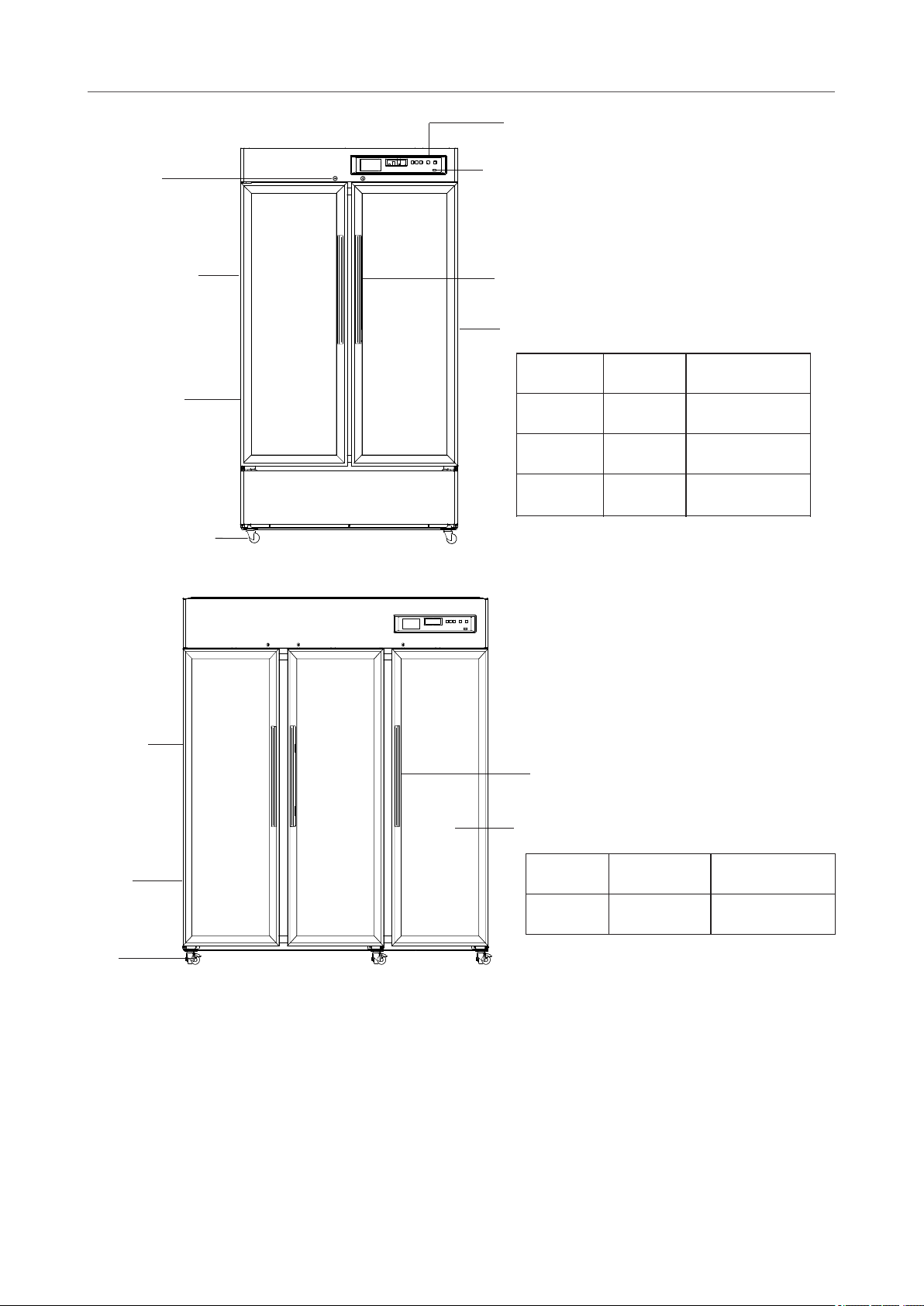
5. Product composition and overview
Figure I YC-55L (It can be used as reference for YC-55EL, YC-56L,YC-56EL,YC-75L,YC-76L, YC-75EL, YC-76EL)
Figure II YC-130L
Door lock
Door handle
Cabinet
Adjust feet
Caster
Door body
USB interface
Display panel
The YC-55L/YC-56L/YC-55EL/YC-56EL refrigerator has two shelves, each with a capacity of 13Kg.
The YC-75L/YC-76L/YC-75EL/YC-76EL refrigerator has three shelves, each with a capacity of 13Kg.
The YC-130L/ YC-130ELrefrigerator has 2 shelves, the carrying capacity of each shelf and suspension frame is 21Kg.
Adjust feet
Door lock
USB interface
Door body
Display panel
(It can be used as reference for YC-130EL)
8
Figure III YC-395L(It can be used as reference for YC-315L,YC-315EL,YC-330L,YC-330EL, YC-395EL,
YC-400L, YC-400EL and YC-525L,YC-525EL)
Caster Adjust feet
Caster
Door handle
Door body
Figure VI YC-650L
Model
Shelves
Loading capacity
(kg)
YC-650L
5
36
access port
Model
Shelves
Loading capacity
(kg)
YC-315L
4+1
25
YC-330L
5
20
YC-395L
YC-395EL
6+1
25
YC-400EL
YC-400L
6
22
YC-525EL
YC-525L
6
32
Graph recorder
(optional)

7
5. Product composition and overview
Figure I YC-55L (It can be used as reference for YC-55EL, YC-56L,YC-56EL,YC-75L,YC-76L, YC-75EL, YC-76EL)
Figure II YC-130L
Door lock
Door handle
Cabinet
Adjust feet
Caster
Door body
USB interface
Display panel
The YC-55L/YC-56L/YC-55EL/YC-56EL refrigerator has two shelves, each with a capacity of 13Kg.
The YC-75L/YC-76L/YC-75EL/YC-76EL refrigerator has three shelves, each with a capacity of 13Kg.
The YC-130L/ YC-130ELrefrigerator has 2 shelves, the carrying capacity of each shelf and suspension frame is 21Kg.
Adjust feet
Door lock
USB interface
Door body
Display panel
(It can be used as reference for YC-130EL)
8
Figure III YC-395L(It can be used as reference for YC-315L,YC-315EL,YC-330L,YC-330EL, YC-395EL,
YC-400L, YC-400EL and YC-525L,YC-525EL)
Caster Adjust feet
Caster
Door handle
Door body
Figure VI YC-650L
Model
Shelves
Loading capacity
(kg)
YC-650L
5
36
access port
Model
Shelves
Loading capacity
(kg)
YC-315L
4+1
25
YC-330L
5
20
YC-395L
YC-395EL
6+1
25
YC-400EL
YC-400L
6
22
YC-525EL
YC-525L
6
32
Graph recorder
(optional)
9
Except for the metal shell at the bottom, the contact time of the external accessible parts is t≥1 min, while the contact time
of the metal at the bottom is 1 s ≤ t < 10 s.
Intended use:
*Structure and composition: The product consists of cabinet, door (glass door structure or foam door structure),
refrigeration system and control system.
*Scope of application: It is suitable for storing items in hospitals, pharmacies, epidemic prevention stations, research
institutions, biopharmaceuticals and other units.
* Due to the improvement of products and model differences, the actual products may be different from the diagram.
Please refer to the actual products! The diagram is only used for functional parts description.
Caster
Door handle
Door body
access port
Cabinet
Model
Shelves
Loading capacity
(kg)
YC-1505L
18
32
Figure IV YC-1505L
Figure V YC-725L((It can be used as reference forYC-725EL,YC-1015L,YC-1015EL,YC-1320L)
Door handle
Door body
Cabinet
Door lock
access port
Display panel
(power switch
on the back)
USB interface
Model
Shelves
(kg)
Loading capacity
YC-725EL
YC-725L
12
21
YC-1015L
YC-1015EL
12
27.5
YC-1320L
10
35
Caster
This series of products include two control systems, based on which different adjustment methods apply. Please select the
proper adjustment method according to the type of control system with the storage box you purchased.
6. Operating Instructions
c.Defrosting indicator
f.Print indicator
i.Mute indicator
a. Door switch indicator
If the compressor is in working condition, the refrigeration indicator is on; If the compressor is in a shutdown state,
the cooling indicator is off.
j.Low battery level indicator
When the battery voltage is less than 8V, the buzzer will be triggered, the low battery indicator will be on, and the
digital tube will flash the low battery code "BL" alternately at intervals of 3s; When the battery voltage is greater than
12V, the buzzer will be turned off, the low battery indicator will be off, and the digital tube will resume normal display.
k.Serial port indicator
l.Fan indicator
When the evaporator fan is turned on, the fan indicator is on; when the evaporator fan is turned off, the fan indicator
is off.
When the refrigerator enters the defrosting state, the defrosting indicator is always on; When the refrigerator exits the
defrosting state, the defrosting indicator is always off.
d. Key lock indicator
When the keys are in lock state, none of the keys respond, and the key lock lights up. In this case, after pressing the
up key+down key for 3s, you will be prompted to enter the password, which is defaulted as "005." After entering it
correctly, press the Set/Mute Multiplex key, and the key lock will be released. At this time, the key lock indicator will
be off. In the unlock state, if no key is pressed for 60s, the key lock is started, and the key lock indicator is on. Long
press the up key + down key for 3s, and the keys are locked.
The refrigerator is normally powered by 220V/110V. When the input power is turned off, the buzzer will be triggered,
the digital tube flashes the power-off code "PF" alternately at 3s intervals, and the power-off indicator is on. When the
input power is turned on, it returns to normal, and the power-off indicator is off.
g.Door heating indicator
b. WIFI indicator
When the door heating is turned off, the door heating indicator is off; When the door heating is turned on, the door
heating indicator is on.
When the alarm tone key is muted, the indicator is on; When the alarm mute function is canceled, the indicator is
off.
e.Power-off indicator
When the door is opened, the door switch indicator is on; When the door is closed, the door switch indicator is off.
WIFI Pilot Lamp is on when WIFI is connected; it's off when WIFI is disconnected.
When the printer is not working, the indicator is off; When the printer is working, the indicator is on.
h.Refrigeration indicator
When the reserved RS-485 serial port is not connected to the equipment, the serial port indicator will be off; When
the equipment is successfully connected to the reserved RS-485 serial port, the serial port indicator will be on.
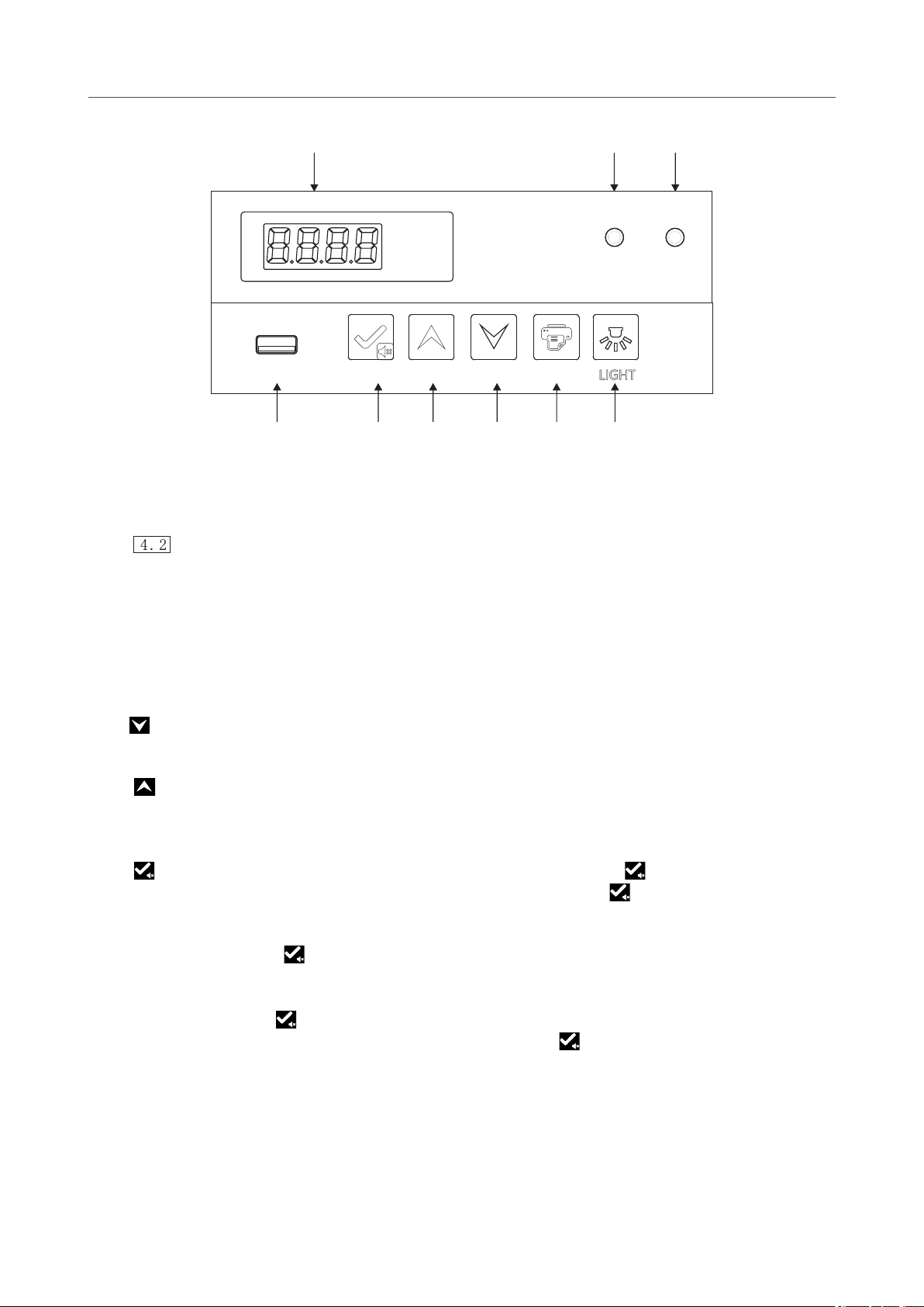
1) Description of display icon indicator
(as shown in the right diagram);
1. Function description of Type A control panel (Except YC-130L,YC-130EL)
10
6.1 Function Introduction
Type A control panel
Printer (optional)
Door
switch
Power
failure
Mute
WIFI
Print
Electric
quantity
Defrosting
Door
heating
Serial
port
Key lock
Refrigeration
Fan

9
Except for the metal shell at the bottom, the contact time of the external accessible parts is t≥1 min, while the contact time
of the metal at the bottom is 1 s ≤ t < 10 s.
Intended use:
*Structure and composition: The product consists of cabinet, door (glass door structure or foam door structure),
refrigeration system and control system.
*Scope of application: It is suitable for storing items in hospitals, pharmacies, epidemic prevention stations, research
institutions, biopharmaceuticals and other units.
* Due to the improvement of products and model differences, the actual products may be different from the diagram.
Please refer to the actual products! The diagram is only used for functional parts description.
Caster
Door handle
Door body
access port
Cabinet
Model
Shelves
Loading capacity
(kg)
YC-1505L
18
32
Figure IV YC-1505L
Figure V YC-725L((It can be used as reference forYC-725EL,YC-1015L,YC-1015EL,YC-1320L)
Door handle
Door body
Cabinet
Door lock
access port
Display panel
(power switch
on the back)
USB interface
Model
Shelves
(kg)
Loading capacity
YC-725EL
YC-725L
12
21
YC-1015L
YC-1015EL
12
27.5
YC-1320L
10
35
Caster
This series of products include two control systems, based on which different adjustment methods apply. Please select the
proper adjustment method according to the type of control system with the storage box you purchased.
6. Operating Instructions
c.Defrosting indicator
f.Print indicator
i.Mute indicator
a. Door switch indicator
If the compressor is in working condition, the refrigeration indicator is on; If the compressor is in a shutdown state,
the cooling indicator is off.
j.Low battery level indicator
When the battery voltage is less than 8V, the buzzer will be triggered, the low battery indicator will be on, and the
digital tube will flash the low battery code "BL" alternately at intervals of 3s; When the battery voltage is greater than
12V, the buzzer will be turned off, the low battery indicator will be off, and the digital tube will resume normal display.
k.Serial port indicator
l.Fan indicator
When the evaporator fan is turned on, the fan indicator is on; when the evaporator fan is turned off, the fan indicator
is off.
When the refrigerator enters the defrosting state, the defrosting indicator is always on; When the refrigerator exits the
defrosting state, the defrosting indicator is always off.
d. Key lock indicator
When the keys are in lock state, none of the keys respond, and the key lock lights up. In this case, after pressing the
up key+down key for 3s, you will be prompted to enter the password, which is defaulted as "005." After entering it
correctly, press the Set/Mute Multiplex key, and the key lock will be released. At this time, the key lock indicator will
be off. In the unlock state, if no key is pressed for 60s, the key lock is started, and the key lock indicator is on. Long
press the up key + down key for 3s, and the keys are locked.
The refrigerator is normally powered by 220V/110V. When the input power is turned off, the buzzer will be triggered,
the digital tube flashes the power-off code "PF" alternately at 3s intervals, and the power-off indicator is on. When the
input power is turned on, it returns to normal, and the power-off indicator is off.
g.Door heating indicator
b. WIFI indicator
When the door heating is turned off, the door heating indicator is off; When the door heating is turned on, the door
heating indicator is on.
When the alarm tone key is muted, the indicator is on; When the alarm mute function is canceled, the indicator is
off.
e.Power-off indicator
When the door is opened, the door switch indicator is on; When the door is closed, the door switch indicator is off.
WIFI Pilot Lamp is on when WIFI is connected; it's off when WIFI is disconnected.
When the printer is not working, the indicator is off; When the printer is working, the indicator is on.
h.Refrigeration indicator
When the reserved RS-485 serial port is not connected to the equipment, the serial port indicator will be off; When
the equipment is successfully connected to the reserved RS-485 serial port, the serial port indicator will be on.
1) Description of display icon indicator
(as shown in the right diagram);
1. Function description of Type A control panel (Except YC-130L,YC-130EL)
10
6.1 Function Introduction
Type A control panel
Printer (optional)
Door
switch
Power
failure
Mute
WIFI
Print
Electric
quantity
Defrosting
Door
heating
Serial
port
Key lock
Refrigeration
Fan

3) is the set/mute key;
For example, when setting the set temperature, reduce the set temperature.
In parameter setting mode, move to the next parameter or increase the parameter value. For example, when setting
the set temperature, increase the set temperature value. When setting the parameter value, long press the up
button, and the parameter will increase rapidly. Under normal conditions, long press the up key for 3 seconds to
import the data of the USB flash drive in 12 months.
View ambient temperature:
In parameter setting mode, move to the previous parameter or decrease the parameter value.
Humidity check: key unlocked state, long press and , digital tube display humidity, no press any Key
operation after 5 seconds or press and , return to normal display.
When setting the parameter value, long press the down button, and the parameter will decrease rapidly.
7) is a light switch key;
4) is a up key;
When the equipment is powered on, the lights are turned off by default.
8) USB data export;
Note: When there is less data, the digital tube will not display "on" and "End".
Manual export: In the key unlock state, and when the USB flash drive is connected and the file is not being
generated, press the key up for 3 seconds, and the digital tube will display "d01." Press the up key or down key to
adjust "d00~d12," and press key to obtain the file generation (d00) or generate the PDF file of the record data
of the previous months (1-12).
In the key lock state, press key, and digital tube displays the ambient temperature, and returns to normal
display after 5 s without key operation, or pressing and . In the key unlock state, press key, and digital
tube displays ambient temperature, and returns to normal display after 5s without key operation.
In unlock state and parameter setting mode, press this key to display parameter values and parameter names. If the
pressing time is longer than 3 seconds, save the settings and return to the normal interface.
5) is a down key;
6) is a print key;
Automatic export: when the U disk is connected to the USB interface, the recorder buzzer will chirp once and
display "on". PDF files of data that not currently exported will be generated in the U disk. After data transmission,
the buzzer will chirp once again and display "End".After 6s, it will return to normal display.
The system can keep 7 days of data for printing, and press the print key to print the temperature within the set time
period.
2) temperature display window, which displays the average temperature inside the cabinet in °C under normal
operation;
In case of no alarm state and key unlock state, press , and display the ambient temperature for 5s and then
return to normal display; In the unlock state, press for more than 3s, and enter the user menu.
When buzzer is triggered (including cabinet high temperature alarm, door opening alarm, sensor failure alarm, etc.)
and in the key unlock state, press for the first time, and the buzzer stops ringing, and the ambient temperature
is displayed for 5s, after which the normal display is resumed (pressing the mute button is only to turn off the buzzer
for alarming this abnormal state, for example troubleshooting, and the buzzer will be triggered next time for any
abnormality). Then press again, trigger the buzzer, display the ambient temperature for 5s, and resume the
display of chamber temperature and alarm state. In the key unlock state, can be used as a setting key.
11
2) User parameter settings:
1) After powering on, the equipment can enter the working state;
3) Press for more than 3s, or press no key in 60s to exit the parameter setting program.
Unlock:under normal operating state,simultaneously press and keys for 3s and the digital tube will
display the parameter code”0000";By pressing to enter the password”0005"and holding to unlock.
Then press key for 3s,the digital tube will display the parameter code”PS1"and enter the setting and
adjustment parameters.Use or key to scroll the parameters;
b. Press key to display the corresponding parameter value;
d. Use to temporarily store the modified values and return to the display parameters;
e. If other parameters are modified, repeat steps ① to ④;
2. Function setting of Type A control panel
c. Use or key to scroll the parameters;
a. Use or key to scroll the parameters;
f. Press for more than 3s, save the modified parameters and return to the display parameter category.
4)Parameter display
12
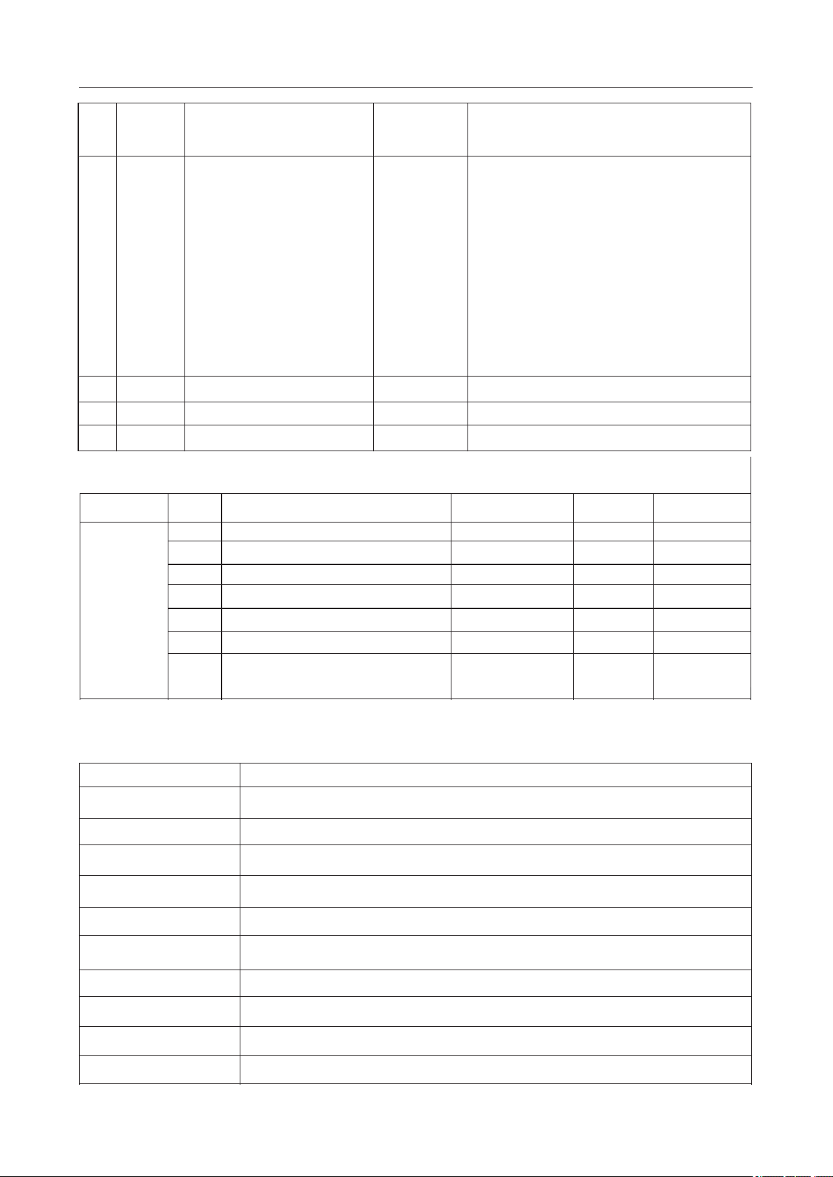
No.
Menuitem
Parameter Range
Suggested
settings
Remarks
1
MAX
_
_
The highest temperature since last clerance
2
MIN
_
_
The lowest temperature since last clerance
3
CLR
_
_
Clearance of the Max and Min temperature
records
4
Set
0.0-10.0
5.0
Temperature setting
5
H
0.0-10.0
5.0
Set value of high temperature alarm set+H;
When H =0, High temp alarm is disabled; When
the alarm is over high temp alarm set, H1 will be
displayed on the controller
6
L
0.0-10.0
5.0
Set value of low temperature alarm set-L; When
L =0, Low temp alarm is disabled; When the
alarm is below low temp alarm set, L1 will be
displayed on the controller
7
n
Set logger module time - year
_
_
8
y
Set logger module time - month
_
_
9
r
Set logger module time - day
_
_
10
s
Set logger module time - hour
_
_
11
F
Set logger module time - minute
_
_
12
Pt
0-240min
20
Print interval
13
tH1
20.0-50.0℃
40.0
Upper limit of ambient temperature alarm

3) is the set/mute key;
For example, when setting the set temperature, reduce the set temperature.
In parameter setting mode, move to the next parameter or increase the parameter value. For example, when setting
the set temperature, increase the set temperature value. When setting the parameter value, long press the up
button, and the parameter will increase rapidly. Under normal conditions, long press the up key for 3 seconds to
import the data of the USB flash drive in 12 months.
View ambient temperature:
In parameter setting mode, move to the previous parameter or decrease the parameter value.
Humidity check: key unlocked state, long press and , digital tube display humidity, no press any Key
operation after 5 seconds or press and , return to normal display.
When setting the parameter value, long press the down button, and the parameter will decrease rapidly.
7) is a light switch key;
4) is a up key;
When the equipment is powered on, the lights are turned off by default.
8) USB data export;
Note: When there is less data, the digital tube will not display "on" and "End".
Manual export: In the key unlock state, and when the USB flash drive is connected and the file is not being
generated, press the key up for 3 seconds, and the digital tube will display "d01." Press the up key or down key to
adjust "d00~d12," and press key to obtain the file generation (d00) or generate the PDF file of the record data
of the previous months (1-12).
In the key lock state, press key, and digital tube displays the ambient temperature, and returns to normal
display after 5 s without key operation, or pressing and . In the key unlock state, press key, and digital
tube displays ambient temperature, and returns to normal display after 5s without key operation.
In unlock state and parameter setting mode, press this key to display parameter values and parameter names. If the
pressing time is longer than 3 seconds, save the settings and return to the normal interface.
5) is a down key;
6) is a print key;
Automatic export: when the U disk is connected to the USB interface, the recorder buzzer will chirp once and
display "on". PDF files of data that not currently exported will be generated in the U disk. After data transmission,
the buzzer will chirp once again and display "End".After 6s, it will return to normal display.
The system can keep 7 days of data for printing, and press the print key to print the temperature within the set time
period.
2) temperature display window, which displays the average temperature inside the cabinet in °C under normal
operation;
In case of no alarm state and key unlock state, press , and display the ambient temperature for 5s and then
return to normal display; In the unlock state, press for more than 3s, and enter the user menu.
When buzzer is triggered (including cabinet high temperature alarm, door opening alarm, sensor failure alarm, etc.)
and in the key unlock state, press for the first time, and the buzzer stops ringing, and the ambient temperature
is displayed for 5s, after which the normal display is resumed (pressing the mute button is only to turn off the buzzer
for alarming this abnormal state, for example troubleshooting, and the buzzer will be triggered next time for any
abnormality). Then press again, trigger the buzzer, display the ambient temperature for 5s, and resume the
display of chamber temperature and alarm state. In the key unlock state, can be used as a setting key.
11
2) User parameter settings:
1) After powering on, the equipment can enter the working state;
3) Press for more than 3s, or press no key in 60s to exit the parameter setting program.
Unlock:under normal operating state,simultaneously press and keys for 3s and the digital tube will
display the parameter code”0000";By pressing to enter the password”0005"and holding to unlock.
Then press key for 3s,the digital tube will display the parameter code”PS1"and enter the setting and
adjustment parameters.Use or key to scroll the parameters;
b. Press key to display the corresponding parameter value;
d. Use to temporarily store the modified values and return to the display parameters;
e. If other parameters are modified, repeat steps ① to ④;
2. Function setting of Type A control panel
c. Use or key to scroll the parameters;
a. Use or key to scroll the parameters;
f. Press for more than 3s, save the modified parameters and return to the display parameter category.
4)Parameter display
12
No.
Menuitem
Parameter Range
Suggested
settings
Remarks
1
MAX
_
_
The highest temperature since last clerance
2
MIN
_
_
The lowest temperature since last clerance
3
CLR
_
_
Clearance of the Max and Min temperature
records
4
Set
0.0-10.0
5.0
Temperature setting
5
H
0.0-10.0
5.0
Set value of high temperature alarm set+H;
When H =0, High temp alarm is disabled; When
the alarm is over high temp alarm set, H1 will be
displayed on the controller
6
L
0.0-10.0
5.0
Set value of low temperature alarm set-L; When
L =0, Low temp alarm is disabled; When the
alarm is below low temp alarm set, L1 will be
displayed on the controller
7
n
Set logger module time - year
_
_
8
y
Set logger module time - month
_
_
9
r
Set logger module time - day
_
_
10
s
Set logger module time - hour
_
_
11
F
Set logger module time - minute
_
_
12
Pt
0-240min
20
Print interval
13
tH1
20.0-50.0℃
40.0
Upper limit of ambient temperature alarm
13
Code
Error Description
H1
High temperature alarm
L1
Low temperature alarm
H2
Alarm for high ambient temperature
H3
Condenser overheat alarm
do
Door opening alarm
PF
Power failure alarm
bL
Battery low alarm
Er
The recorder is not connected
LoF
Recorder did not start
EE
Communication failure
4. Alarm display
After the power-on self-test on the display board is completed, the quick setting menu is displayed.
Quick setting of time after power on
If there is no operation for 60 seconds under the quick setting menu, it will automatically exit the quick setting
menu and return to normal display.
Menu item
Menu
Menu description
Set range
Default
Unit
menu
Settings
Quick
n
Set logger module time - year
10~50
/
y
Set logger module time - month
1~12
--
/
r
Set logger module time - day
01~31
--
/
S
Set logger module time - hour
00~23
--
/
F
Set logger module time - minute
00~59
--
/
Pt
Print interval
0~240
20
min
SCY
Temperature data recording period
0~240
0: shielded
recorder
10
min
When buzzer is triggered (including cabinet high alarm, door opening alarm, sensor failure alarm, etc.) and in the
button unlock state, press for the first time, and the buzzer stops ringing, and the ambient temperature is
displayed for 5s, after which the normal display is resumed (pressing the mute button is only to turn off the buzzer
for alarming this abnormal state, for example trouble removal, and the buzzer will be triggered next time for any
abnormality). Then press again, trigger the buzzer, display the ambient temperature for 5s, and then resume the
display of cabinet temperature and alarm state. In the key unlock state, can be used as a setting key.
1. Function description of Type B control panel (Applicable to YC-130L YC-130EL)
a. It is temperature display window, which displays the average temperature inside the cabinet in °C under
normal operation; Different prompt characters can be displayed in the setting state (see below for details).
f.: In parameter setting mode, reduce the parameter value. For example, when setting the set temperature,
reduce the set temperature. When setting the parameter value, long press the down button, and the parameter will
decrease rapidly.
h. :is the set/mute key; In case of no alarm state and key unlock state, press , and display the ambient
temperature for 5s and then return to normal display; In the unlock state, press for more than 3s, and enter the
user menu.
d.“LIGHT” : After the machine is powered on, the light is off by default, and the on-off of the light can be adjusted by
the on-off key.
b.Door opening indicator: When the refrigerator door is opened, the indicator lights up. After more than 1 minute,
the door opening alarm indicator will be on and the buzzer triggered, displaying "do".
c.Fault indicator: When the product runs normally, the indicator is off; The indicator is on for operation abnormality.
e. “PRINT “ (optional): The system can keep 7 days of data for printing. Press the print key to print the temperature
within the set time period.
g. : In parameter setting mode, increase the parameter value. For example, when setting the set temperature,
increase the set temperature value. When setting the parameter value, long press the up button, and the parameter
will increase rapidly. Under normal conditions, long press the up key for 3 seconds to import the data of the USB
flash drive in 12 months.
Type B control panel
ac
b
e
f
g
h
i d
14
(optional) (optional)
TEMPERATURE CONTROL PRINT
USB
DOOR ALARM
°C
Ref.
No.
Menuitem
Parameter Range
Suggested
settings
Remarks
14
P1
5. Always off
1. Automatic heating mode 1
4. Always on
2. Automatic heating mode 2
3. Automatic heating mode 3
1.(Set to 4
when
the door is with
condensation)
(Set to 5 when
the door is a
foaming door)
(Set to 1 when
the door is a
glass door)
Mode 4: Door heating is always on;
Mode 5: Door heating is always off.
Mode 1: It shall be judged as once after the door
is opened and closed once and heated for 5min
(time setting). If the door is opened and closed
again during the heating period, the heating time
will be updated again;
Mode 2: When the compressor runs, heater is
on;When the compressor stops, the heater Will
automatically off after one min
Mode 3: When the humidity in the cabinet is
more than 80%, the door heating is on, and
when the humidity in the cabinet is moderately
less than 60%, the door heating is off;
15
Ps1
0000-9999
0005
User menu password settings
16
b1
_
_
Repair Information 1
17
b2
_
_
Repair Information 2

In unlock state and parameter setting mode, press this key to display parameter values and parameter
names. If the pressing time is longer than 3 seconds, save the settings and return to the normal interface.
i. USB interface
Automatic export of USB data: When the USB interface is connected to the USB flash drive, the buzzer of
the recorder beeps once, displaying "ON", and PDF files of the data of the current month and the previous
month are generated in the USB flash drive. After the data transmission is completed, the buzzer beeps
once, displaying "End," and the normal display resumes after 6s.
Note: When there is less data, "on" and "end" prompts are not displayed.
Note: When the alarm of the digital tube flashes and displays "LoF," the recorder is not started;
Meanwhile press and key for 3s,and "LoF" disappears, the recorder is started.
Manual export of USB data: In the key unlock state, when the USB flash drive is connected and the file is not being
generated, press the up key for 3 seconds, and the digital tube in the lower chamber will display "d01." Press the
key up or down key to adjust "d00~d12," and press key to cancel the file generation (d00) or generate the PDF
file of the record data of the previous months (1-12).
15 16
3. Parameter display
No.
Menuitem
Parameter Range
Suggested
settings
Remarks
1
MAX
_
_
The highest temperature since last clerance
2
MIN
_
_
The lowest temperature since last clerance
3
CLR
_
_
Clearance of the Max and Min temperature
records
4
Set
0.0-10.0
5.0
Temperature setting
5
H
0.0-10.0
5.0
Set value of high temperature alarm set+H;
When H =0, High temp alarm is disabled; When
the alarm is over high temp alarm set, H1 will be
displayed on the controller
6
L
0.0-10.0
5.0
Set value of low temperature alarm set-L; When
L =0, Low temp alarm is disabled; When the
alarm is below low temp alarm set, L1 will be
displayed on the controller
7
n
Set logger module time - year
_
_
8
y
Set logger module time - month
_
_
9
r
Set logger module time - day
_
_
10
s
Set logger module time - hour
_
_
11
F
Set logger module time - minute
_
_
12
Pt
0-240min
20
Print interval
13
tH1
20.0-50.0℃
40.0
Upper limit of ambient temperature alarm
14
P1
5. Always off
2. Automatic heating mode 2
1. Automatic heating mode 1
4. Always on
3. Automatic heating mode 3
1.(Set to 4
when
the door is with
condensation)
(Set to 1 when
the door is a
glass door)
(Set to 5 when
the door is a
foaming door)
Mode 5: Door heating is always off.
Mode 3: When the humidity in the cabinet is
more than 80%, the door heating is on, and
when the humidity in the cabinet is moderately
less than 60%, the door heating is off;
Mode 4: Door heating is always on;
Mode 2: When the compressor runs, heater is
on;When the compressor stops, the heater Will
automatically off after one min
Mode 1: It shall be judged as once after the door
is opened and closed once and heated for 5min
(time setting). If the door is opened and closed
again during the heating period, the heating time
will be updated again;
15
Ps1
0000-9999
0005
User menu password settings
16
b1
_
_
Repair Information 1
17
b2
_
_
Repair Information 2
b. Press key to display the corresponding parameter value;
2. Function setting of Type A control panel
c. Use or key to scroll the parameters;
3)Press for more than 3s, save the modified parameters and return to the display parameter category.
a. Use or key to scroll the parameters;
Unlock:under normal operating state,simultaneously press and keys for 3s and the digital tube will
display the parameter code”0000";By pressing to enter the password”0005"and holding to unlock.
Then press key for 3s,the digital tube will display the parameter code”PS1"and enter the setting and
adjustment parameters.Use or key to scroll the parameters;
1) After powering on, the equipment can enter the working state;
2) User parameter settings:
d. Use to temporarily store the modified values and return to the display parameters;
e. If other parameters are modified, repeat steps ① to ④;
4) Press for more than 3s, or press no key in 60s to exit the parameter setting program.
This manual suits for next models
26
Table of contents


