MEMMINGER-IRO MSF 3 User manual

English translation of the original
German instruction manual
English
08-920-002-01
20.02.13
MSF 3
*08-920-002-01*


1
Introduction
Congratulations and thank you for choosing a quality product from MEMMINGER IRO. To ensure that you get the
optimum performance from this product you should be fully familiar with all its features and functions.
For this reason we ask you to read this instruction manual carefully before starting to use the product. This manual
containsimportantinformationandinstructions,whichmustbeobservedwhenusingthisequipment.Keepthismanual
for future reference.
Introduction / Contents
Contents
Introduction................................................................................................................................................................1
Contents.....................................................................................................................................................................1
Safety..........................................................................................................................................................................2
Permitted Uses............................................................................................................................................................2
Safety Precautions ......................................................................................................................................................2
Warranty......................................................................................................................................................................2
Disposal.......................................................................................................................................................................2
Symbols used in this manual.......................................................................................................................................2
General Description ..................................................................................................................................................3
Unit components..........................................................................................................................................................3
Function.......................................................................................................................................................................3
Features ......................................................................................................................................................................3
Installation..................................................................................................................................................................4
Connecting the contact cable......................................................................................................................................4
Fitting the at ring holder.............................................................................................................................................4
MEMMINGER-IRO GMBH Power Supply Units..........................................................................................................5
Fitting the round tube holder........................................................................................................................................5
Function check ............................................................................................................................................................5
Installing the input tensioner (optional)........................................................................................................................6
Fit the compensation tensioner (optional) ...................................................................................................................6
Fit the brush tensioner (optional).................................................................................................................................6
Fitting the output stop device (optional).......................................................................................................................7
Operation....................................................................................................................................................................8
Switching on................................................................................................................................................................8
Switching off................................................................................................................................................................8
Threading ....................................................................................................................................................................8
Adjusting the yarn tension at the outlet .......................................................................................................................9
Yarn changeover.........................................................................................................................................................9
Calibrating the unit.....................................................................................................................................................10
Servicing ..................................................................................................................................................................11
Changing the magnetic tensioner..............................................................................................................................11
Cleaning the yarn sensors.........................................................................................................................................11
Cleaning the remaining parts of the unit....................................................................................................................11
Dimensions..............................................................................................................................................................12
Technical Data.........................................................................................................................................................12
Troubleshooting......................................................................................................................................................13
Declaration of incorporation and conformity .......................................................................................................14

2
Safety
Permitted Uses
The MSF 3 storage feeder is designed solely for feeding
yarntotextilemachines.Anyotherusesarenotpermitted.
Themanufacturerwillnotacceptanyliabilityfordamages
resulting from non-permitted uses. The user is liable for
damages resulting from non-permitted uses.
Safety Precautions
The safety risks inherent in the equipment must be
reevaluated once it has been installed in the nal unit.
This equipment must only be operated by suitably quali-
ed and authorised personnel. Operators must receive
detailed instructions in the use of the equipment. Opera-
tors must be informed of any hazards related to the use
oftheequipmentandtheprotectivemeasuresnecessary.
The operator is responsible for ensuring that all instruc-
tions regarding the electrical installation, tting, operation
and maintenance are implemented.
Cautionisadvisedin theimmediatevicinityofthedevice.
Donottouchtheequipmentwhenitisrunning.Themoving
parts can cause injury. Turn off the unit before working
in this area. In the normal operating mode the unit can
start to operate without warning.
For your own safety wear safety footwear, a hair net, ear
protectors and close-tting clothing. Due to the increased
risk of injury, please do not wear loose hanging clothing,
such as ties, scarves, long hair, rings or other jewellery.
Only operate the device when it is problem-free.
Check the device for damage and other changes once
every shift. The device should not be operated if it is
damaged.
Do not carry out any cleaning when the knitting machine
is running. Before maintenance or servicing, switch off
and lock out the knitting machine. Take precautions to
prevent accidental or unauthorised start-up. The main
switch can be secured with a padlock so that it cannot
be switched back on.
Only qualied electricians working in accordance with
current electrical engineering practices and regulations
are permitted to perform installation and servicing.
Check that the operating voltage is within the permitted
range of the device and that there is a high speed (HS)
protection fuse for the knitting machine.
The device has electronic components which
are sensitive to interference from electrostatic
charges. Before you open the unit casing, you
shouldtakeprecautions topreventelectrostatic charges.
You can discharge any electrostatic charges beforehand
by touching a metal surface (e.g. the machine or the
knitting cylinder).
The power supply for the device must be taken from the
circularknitting machine.The powersupply tothe device
must be switched on and off from the main switch of the
circular knitting machine. This means that it can only
receive power when the machine is switched on.
Youmustdisconnecttheknittingmachinefromthepower
supply before moving it, however small the distance.
Reconnect the power supply before restarting.
The unit complies with the EMC Directive for use in
industrial environments.
The device should not be used in an area where there is
a risk of re or an area classed under European Direc-
tive 94/9/EC. Please contact MEMMINGER-IRO GMBH,
if you would like a product for this type of environment.
We operate a policy of continuous improvement and
reserve the right to make product changes without prior
notice. Functions and compatibility remain unchanged.
Only use original spare parts and accessories.
Warranty
Failure to follow the instructions in this manual will void
yourwarranty.Themanufacturerwillnotacceptanyliability
for damages or operating faults resulting from failure to
follow the instructions in this manual.
Disposal
Decommission and dispose of old equipment in com-
pliance with the current regulations for the disposal of
electrical equipment with electronic parts.
Symbols used in this manual
CAUTION!
This symbol marks important instructions
where failure to follow the instructions can
cause personal injury or damage to the equipment.
NOTE!
This symbol marks useful information which
willhelpyoutogetthebestfromtheequipment.
i
!

3
General Description
Function
The reeling device within the winding reel transports and
separatestheyarnwindingsmakingitpossibletoprocess
even the most difcult yarns.
The conical magnetic tensioner ensures a constant yarn
tension at the output.
Thehigh-performance,brushlessDCmotorismicroproc-
essor controlled. Sensors on the winding reel monitor
andcalculate theaverageyarn usagerateandadjustthe
motor speed to the yarn usage accordingly.
Features
►Yarn control on the winding reel using contactless
sensors to prevent yarn tension peaks. The MSF 3
operates continuously, without starting and stopping.
►The stationary winding reel eliminates the need for
extra yarn windings and can operate at higher yarn
speeds than those possible with rotary winding reels.
The yarn separation is 1 mm.
►Theadjustableconical magnetictensionerat theyarn
outfeedisanew,patenteddevelopment,whichmakes
it possible to work with a wide range of yarn tensions
and which can be used for all yarn types.
Unit components
1 - Outlet eyelet
2 - Tension selector knob
3 - Tensioner
4 - Cover
5 - ON/OFF button
6 - Light cover lens
7 - Sensors
8 - Reector
9 - Ceramic eyelet
10 - Contact pins
11 - Inlet eyelet
12 - Winding plate
13 - Winding reel
14 - Tension cone
15 - Yarn tension scale
16 - Threading needle
MSF 3
4
Installation
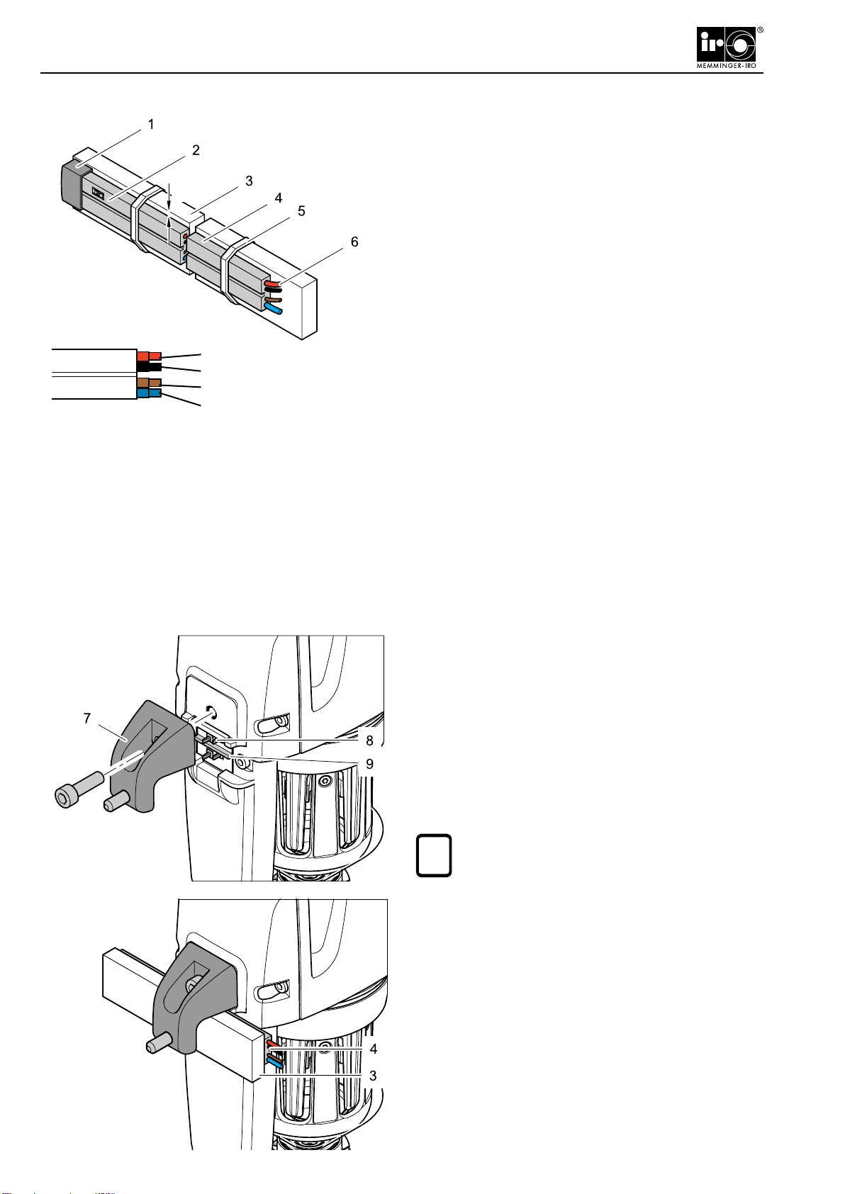
Connecting the contact cable
►Fix the contact cable (4) with cable ties (5) to the
feeder support ring (3) (3 to 10 mm thick, 25 to 30
mm wide).
The red wire (6) of the contact cable must be at the top.
The text (2) on the contact cable must be visible.
The contact cable must be positioned 3 mm below the
top edge of the feeder ring.
►Switchon the powersupply.Use a voltmeterto check
that the contact cable has been installed correctly.
Forstandardunits,thevoltagemeasuredbetweenthered
and blue wires must be 57 V DC ±10% when the knitting
machine is switched on. For reduced powered units the
voltage tested should be 35 V DC ±10%.
►Ensure that the polarity is correct.
►Insulate the ends of the cables using MEMMINGER-
IRO GMBH insulating caps 000-721-116 (1).
Voltage 57 V DC
Bus A
Bus B
0 V DC
red
black
brown
blue
MEMMINGER-IRO GMBH
3 mm
Fitting the at ring holder
► Screw the at ring holder (7) to the unit.
►Switch off the power supply.
► Fit the unit to the at ring (3).
The contact cable (4) must be located in the guide (9).
This is the only way of ensuring that the contact pins
(8) effectively make contact with the wire in the contact
cable.
NOTE!
Do not crush the contact cable during this
operation.
i
5
Installation
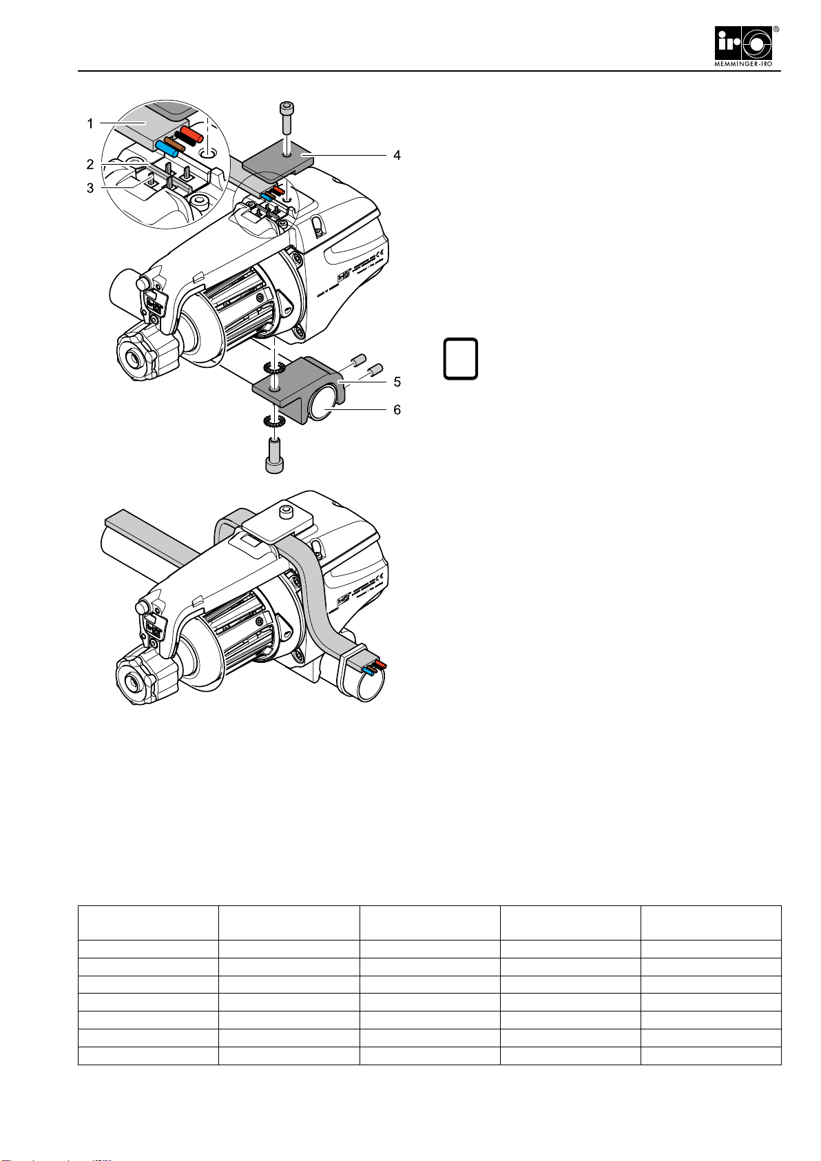
Fitting the round tube holder
►Screw the round tube holder (5) to the unit.
►Fit the unit to the round tube (6).
►Switch off the power supply.
►Clampthecontactcable(1)tothecontactbase.Screw
on the cable clamping plate (4).
The contact cable (1) must be located in the guide (2).
This is the only way of ensuring that the contact pins
(3) effectively make contact with the wire in the contact
cable.
NOTE!
Do not crush the contact cable during this
operation.
Function check
►Switch on the power supply.
► Check that the stop motion device operates ef-
ciently.
►Switch off the power supply.
►Install the remaining units.
►Switch on the power supply at regular intervals and
check the functional efciency of up to 10 units.
i
MEMMINGER-IRO GMBH Power Supply Units
Max. number of
MSF 3 Item no. Power Number of fuse units Max. number per
fuse unit
4 021-000-200 200 VA 1 4
8 021-000-205 320 VA 1 8
10 021-000-210 500 VA 1 10
30 021-000-220 924 VA 1 30
48 021-000-225 1386 VA 2 24
72 021-000-230 1980 VA 2 36
108 021-000-235 3119 VA 2 54
MSF 3
F 3
6
Installation
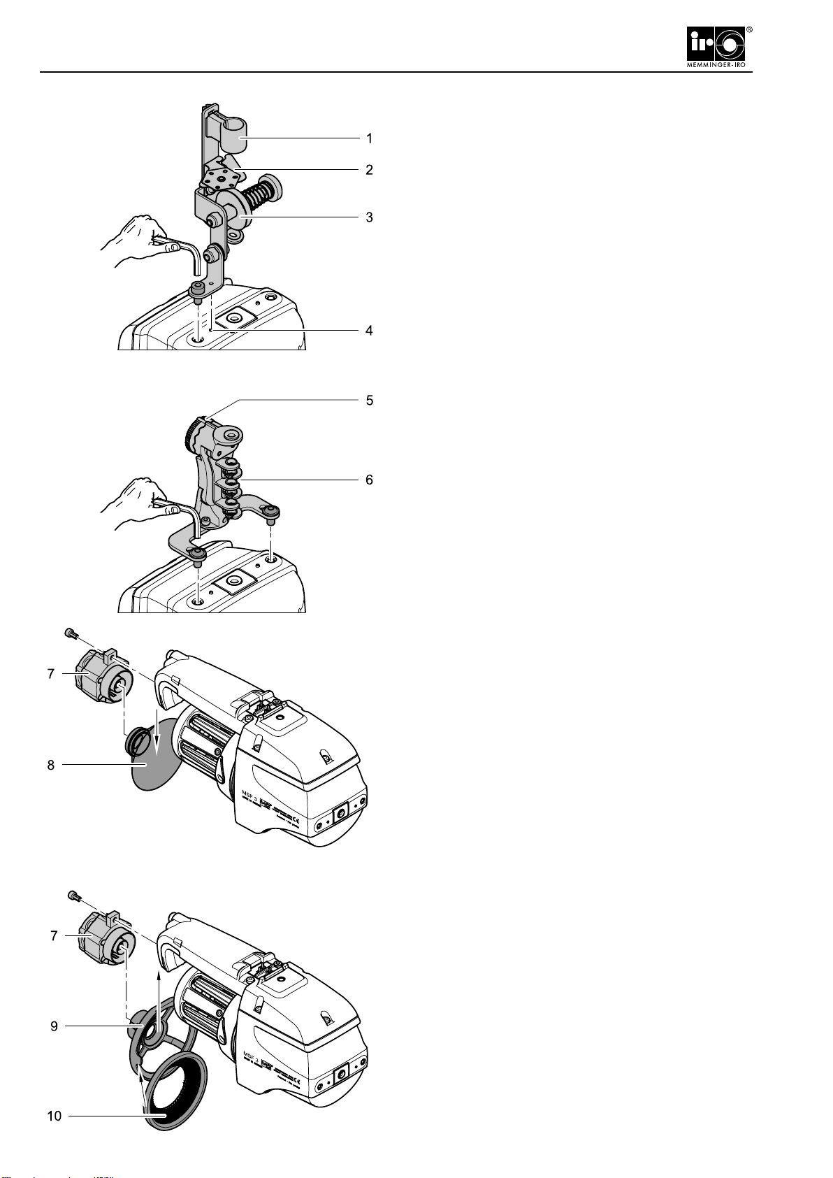
Installing the input tensioner
(optional)
The input tensioner is xed at the yarn inlet of the unit.
Fit the rotation stop (4) to ensure that the input tensioner
does not rotate out of position.
The input tensioner has the following components:
►Tube holder (1).
►Adjustable knot catcher (2).
►Cymbal tensioner (3).
Fit the brush tensioner (optional)
►Remove the tension cone (8).
►Remove the tensioner (7) from the unit.
Fit the compensation tensioner
(optional)
►Screw the compensation tensioner (6) to the unit.
►Set the yarn tension using the setting wheel (5).
►Slide the brush tensioner (10) into the holder (9).
►Screw the tensioner with the holder and the brush
tensioner to the unit.
7
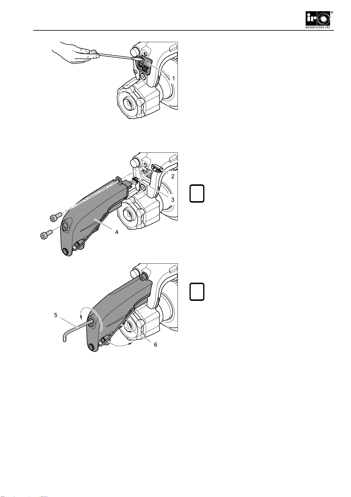
Fitting the output stop device
(optional)
►Remove the cover (1).
►Push the plug (3) into the contact socket (2). Ensure
that the plug engages fully into the socket.
►Screw the output stop device (4) to the unit.
NOTE!
Take care not to crush the cable during this
operation.
Use a 2.5 Alley key (5) to set the force of the output stop
spring.
NOTE!
Check to ensure that the output stop device
can detect a yarn stoppage by releasing the
output sensor (6) from the catch.
i
i
Installation
8
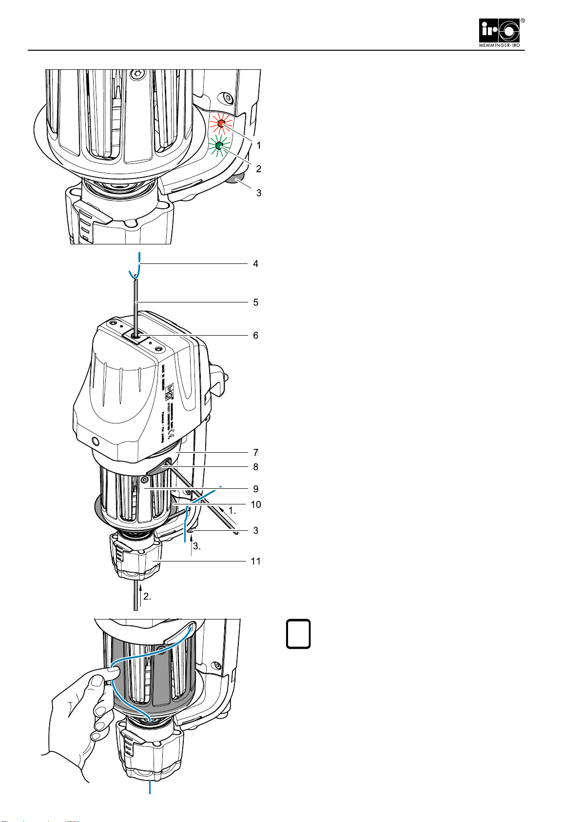
NOTE!
At low yarn tensions it is possible that no yarn
will be fed out.
►Movethestationarypieceofyarnawayfromthewind-
ing reel as shown.
The unit will then wind the yarn onto the winding reel.
Operation
Switching on
►Press the ON/OFF button (3) once.
The unit will check if there are enough yarn windings on
thewindingreel.Iftherearenotenough,themissingwind-
ings will be wound onto the winding reel automatically.
The red LED (1) lights up during this function.
When the unit is ready for operation, the green LED (2)
lights up.
Switching off
►Press and hold down the ON/OFF button for at least
two seconds.
The green LED will switch off.
Threading
►Insert the threading needle (5) through the ceramic
eyelet (8) on the winding plate (7) until the threading
needle comes out through the inlet eyelet (6).
►Pull the yarn (4) through the unit using the threading
needle.
►Push the threading needle from below through the
tensioner (11) until you can see the threading needle
between the winding reel (9) and the tension cone
(10).
►Pull the yarn (4) through the unit using the threading
needle.
►Press the ON/OFF button (3).
The unit will automatically wind the yarn onto the wind-
ing reel.
i
MSF 3
9
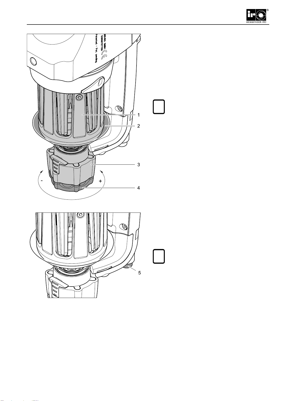
Operation
Adjusting the yarn tension at the
outlet
The yarn tension must be adjusted to match the yarn
type and hardness.
►Turn the knob (4) on the tensioner (3).
The pressure exerted by the tension cone (2) on the
winding reel (1) increases or decreases depending on
the direction in which the knob is rotated.
NOTE!
To ensure a uniform yarn tension, make sure
that the knob engages fully with the tensioner.
i
Yarn changeover
You must reset the unit when changing over to different
yarn types and hardness.
►Press the ON/OFF button (5) once.
NOTE!
Where the yarn changeover involves multiple
unitsyoucanresettheunitscentrallybysimply
switching the knitting machine off and on.
i
10
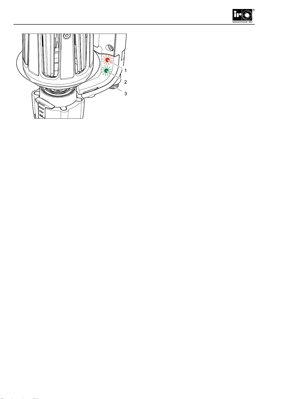
Operation
Calibrating the unit
The unit must be calibrated again if one of the following
faults occur:
- The winding reel runs empty
- The winding reel will not wind on fully
- The winding reel is overwound
►Switch off the unit (3). Press the ON/OFF button for
at least two seconds.
►Remove all the yarn from the unit.
► Press the ON/OFF button ve times in quick succes-
sion.
The unit will start, the red LED (1) will light up ashing and
the green LED (2) will light up for a short time. When the
red LED is permanently on the unit will run continuously.
►Switch off the unit. Press and hold down the ON/OFF
button for at least two seconds.
The unit is now calibrated.
►Thread the unit.
►Switch on the unit.
If calibration is not successful:
The unit starts to run, the red LED ashes slowly and
the green LED lights up permanently. After this the unit
continues to run.
►Clean the yarn sensor.
►Calibrate the unit again.

11
Changing the magnetic tensioner
You can remove the tension cone for cleaning.
►Pull the knob (1).
►Remove the tension cone (3) from the tensioner (2).
Servicing
MSF 3
Cleaning the yarn sensors
Only use the sensor cleaner 09-270-001 or the optional
cleaning brush 000-680-098 to clean the yarn sensors.
►Switch off the unit (4).
►Remove the yarn from the unit.
►Push the sensor cleaner (6) or the cleaning brush (9)
betweenthewindingreel(5)andtheyarnsensors(7).
►Usingthecleaningbrush(8),cleantheoutleteyelet(9).
►Wind the yarn on the unit.
►Switch on the unit.
NOTE!
Do not use chemical cleaners for cleaning the
yarn sensors.
Cleaning the remaining parts of the
unit
►Switch off the unit.
► Blow off any bre dust or dirt with compressed air.
► Wash off the parafn wax and other deposits with
spirits or with a soap solution.
►Switch on the unit.
i
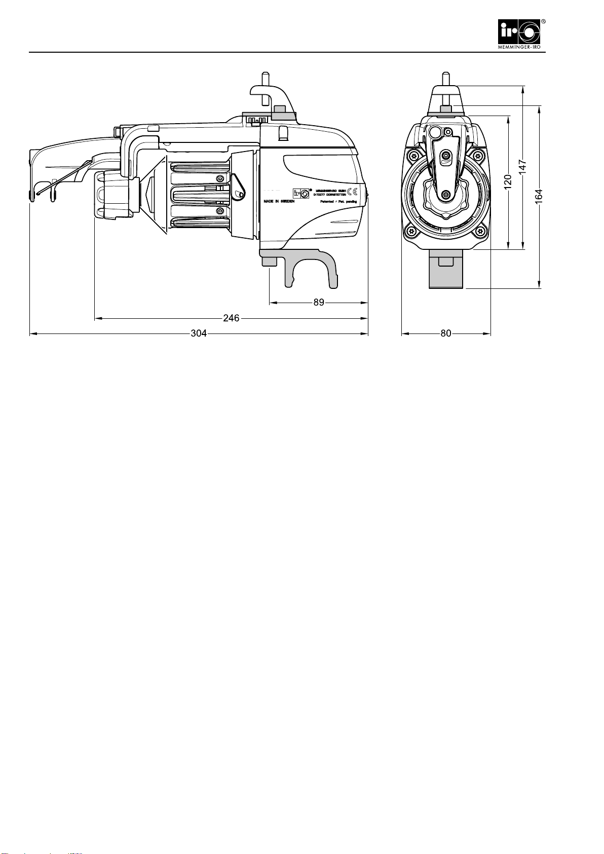
12
Technical Data
Power supply: 57 V DC (35 V DC for reduced power version)
Average current: 0.44 A
Max. power: 85 VA (at a yarn speed of 1100 m/min)
Average power: 25 VA
Max. yarn speed: 1100 m/min (600 m/min for reduced power version)
Yarn gauge range: 17 - 500 dtex
Ambient temperature for operation and storage: +5 °C to +45 °C
Weight: 1.9 kg
Dimensions / Technical data
MSF 3
13
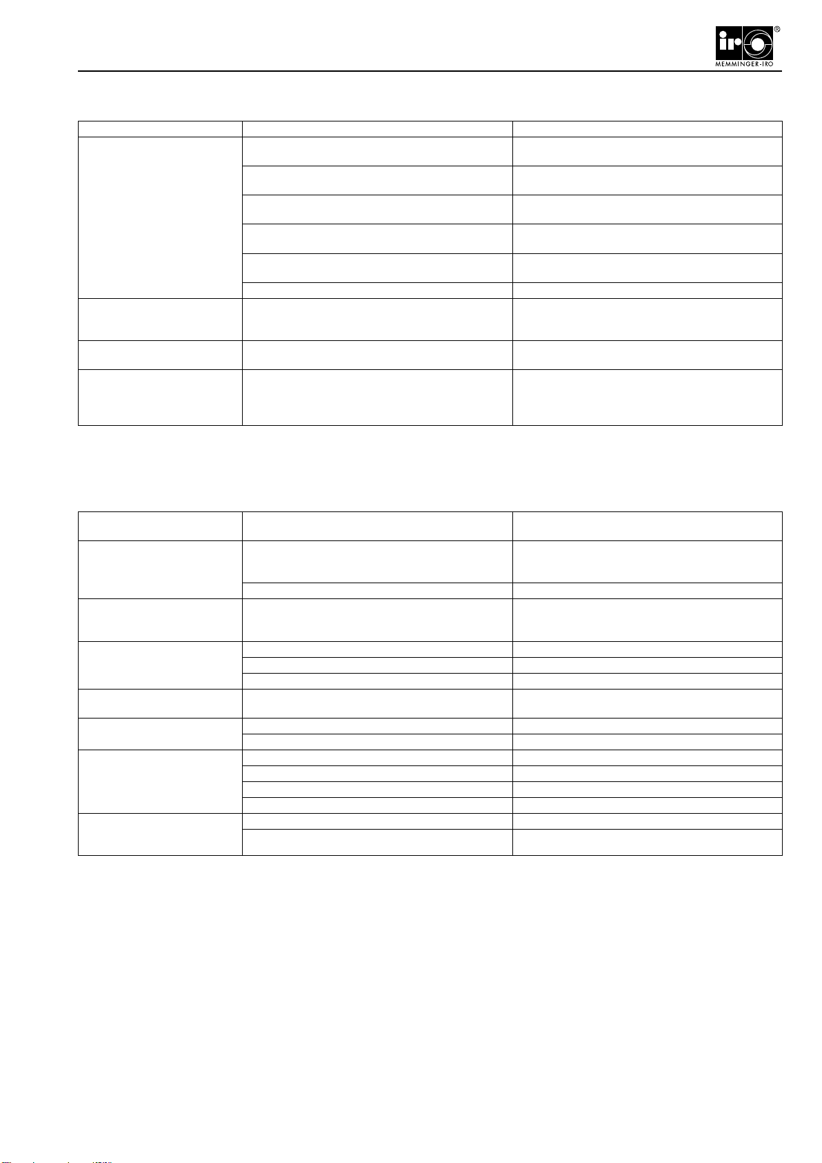
Fault after installation Possible Cause Solution
The unit does not operate. The unit is switched off. Press the ON/OFF button once. The green LED is lit
when the unit is switched on.
The power supply to the power supply unit and the
unit is switched off. Switch on the power supply to the power supply unit.
The contact cable between the power supply unit and
the unit is disconnected. Connect the contact cable to the power supply unit
(see the section, Connecting the contact cable)
The fuses on the power supply unit have blown. Trace and remove the cause. The contact cable may
have caused a short-circuit. Change the fuses.
There is no contact between the unit and the contact
cable. Remove the unit and check that the contact pins t
correctly into the contact cable and make a contact.
Fault in the unit electronics. Change the complete unit.
The unit will not operate and
the stop light is ashing rapidly
(0.12 seconds)
The voltage to the power supply unit is too high or
too low. Check the power supply unit.
The unit winds, but the stop
light remains on. The unit is in the time out mode. Press the ON/OFF button once to reset the unit.
The unit will not operate and
the stop light is lit. The output sensor of the output stop motion device is
in the stop position. Check the yarn guide on the output stop motion
device.
Change the spring tension on the output stop motion
device.
Fault / message during oper-
ating cycle Possible Cause Solution
The winding reel does not wind
up. The winding reel is rotated out of position. The sen-
sors cannot scan the winding reel because the reec-
tors are not directly under the sensors.
Rotate the winding reel until the reector is directly
under the sensor.
The yarn has been changed. Press the ON/OFF button once to reset the unit.
The stop light is ashing slowly
(0.5 seconds). The knitting
machine continues to operate.
The sensors are dirty. Clean the sensors. Press the ON/OFF button once to
reset the unit.
The unit stops the knitting
machine for no obvious reason. A piece of yarn is jammed in the winding plate. Remove the jammed piece of yarn.
The yarn tension before entering the unit is too high. Check the yarn path to the unit.
The sensors are dirty. Clean the sensors.
The knitting machine cannot be
started after troubleshooting. The unit stops the knitting machine from starting. Press the ON/OFF button once to reset the unit.
There are too many windings
on the winding reel. The sensors are dirty. Clean the reector and the sensors.
The yarn has been changed. Press the ON/OFF button once to reset the unit.
The unit stops the knitting
machine because the winding
reel is empty.
The sensors are dirty. Clean the reector and the sensors.
The tension cone is damaged. Change the tension cone.
The yarn demand speed is over 1100 m/min. Reduce the yarn speed.
The yarn has been changed. Press the ON/OFF button once to reset the unit.
The unit stops the knitting
machine and the stop light is
ashing rapidly (0.12 seconds)
Voltage too low or too high. Check the power supply.
Software error. Contact your sales representative.
Troubleshooting
Troubleshooting

14
Declaration of incorporation and conformity
Declaration of incorporation
In conformity with EU Machinery Directive 2006/42/EC, Annex II B
In conformity with the EU Low Voltage Directive 2006/95/EC
also
Declaration of conformity
In conformity with the EU Electro Magnetic Compatibility (EMC) Directive, 2004/108/EC
The manufacturer: MEMMINGER-IRO GMBH
Jakob-Mutz-Straße 7
72280 Dornstetten, Germany
hereby certies that the following subassembly
Product name: MSF 3, MSF 3 CAN
conforms to the requirements of the above named directives.
The subassembly is supplied complete with an original instruction manual and original technical documentation.
The subassembly may not be put into service until the machinery into which it is to be incorporated has been declared
as being in conformity with the provisions of the EU Machinery Directive 2006/42/EC, Annex II A.
______________________________
Dornstetten, 20.02.2013 M. Kleindorp, Company Management


MEMMINGER-IRO GMBH Tel.: +49 7443 281-0
Postfach 1240 Fax: +49 7443 281-101
Jakob-Mutz-Straße 7 Internet: www.memminger-iro.de
72280 Dornstetten - Germany
© 2011 MEMMINGER-IRO GMBH / 72277 Dornstetten - Germany
Nachdruck, auch auszugsweise, nur mit schriftlicher Genehmigung der MEMMINGER-IRO GMBH.
Änderungen vorbehalten.
Reprint, even in extracts, shall require the written approval of MEMMINGER-IRO GMBH.
Subject to modications.
Table of contents
Other MEMMINGER-IRO Sewing Machine manuals


