MENEGOTTI MPT 36 User manual

Point your cell phone or tablet camera
to access the updated version of
Technical Manuals
and
Parts
Catalogs
online, or click the link below
to access the website.
QR-Code:
www.sites.google.com/view/menego-engenharia-docs
MENEGOTTI TECHNICAL MANUAL
Attention:
Illustrave images.
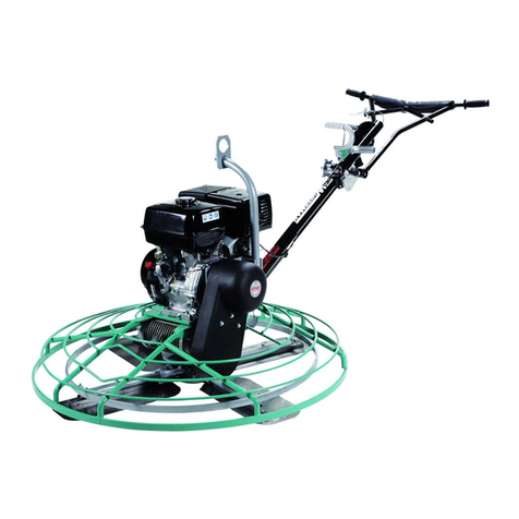
POWER TROWEL
MPT 36 | MPT 46
40730148 - Power Trowel MPT 36 without Engine (Prepared for Honda GX160 Engine)
40730149 - Power Trowel MPT 36 with Menego 200 6,5hp Engine
40730158 - Power Trowel MPT 46 with Menego 270 9,0hp Engine
40730159 - Power Trowel MPT 46 without Engine (Prepared for Honda GX270 Engine)
Before operate
Menego
equipament, read this
Technical Manual
, itself will inform and instruct the
operator about the operaon.
By the way, you avoid possible working accidents
and early maintenance on at the equipment.
Discount-Equipment.com

We sell worldwide for the brands: Genie, Terex, JLG, MultiQuip, Mikasa, Essick, Whiteman,
Mayco, Toro Stone, Diamond Products, Generac Magnum, Airman, Haulotte, Barreto, Power
Blanket, Nifty Lift, Atlas Copco, Chicago Pneumatic, Allmand, Miller Curber, Skyjack, Lull,
Skytrak, Tsurumi, Husquvarna Target, Stow, Wacker, Sakai, Mi-T-M, Sullair, Basic, Dynapac,
MBW, Weber, Bartell, Bennar Newman, Haulotte, Ditch Runner, Menegotti, Morrison, Contec,
Buddy, Crown, Edco, Wyco, Bomag, Laymor, EZ Trench, Bil-Jax, F.S. Curtis, Gehl Pavers, Heli,
Honda, ICS/PowerGrit, IHI, Partner, Imer, Clipper, MMD, Koshin, Rice, CH&E, General Equip-
ment ,Amida, Coleman, NAC, Gradall, Square Shooter, Kent, Stanley, Tamco, Toku, Hatz,
Kohler, Robin, Wisconsin, Northrock, Oztec, Toker TK, Rol-Air, APT, Wylie, Ingersoll Rand /
Doosan, Innovatech, Con X, Ammann, Mecalac, Makinex, Smith Surface Prep,Small Line,
Wanco, Yanmar
Discount-Equipment.com is your online resource for
commercial and industrial quality parts and equipment sales.
561-964-4949
visit us on line @ www.discount-equipment.com
TO PURCHASE THIS PRODUCT PLEASE CONTACT US
Select an option below to find your Equipment
Equipment Financing and
Extended Warranties Available
Discount-Equipment.com

02
Index
Aenon: For beer comodity, store and keep this manual in a properly
spot so it can be easily checked.
Aer sales Departament
and Technical Assistance MENEGOTTI.
With the highest quality, projected and built especially to serve your
needs.
This manual was elaborated to provides the informaons and key instruc-
ons to use and mantain our product, in addicon presents their technical
characteriscs.
Before use the product for the first me, read and pay aenon at the
informaons in this manual.
The product durability only depends the way you treat it in service (opera-
on) and the sasfactory working is consequence of yours regular work
carefully.
Menego is preparaded to offer you all technical assistance, and aend
all your needs about replacement parts.
Welcome, you are part of the huge Menego “customers familiy”.
Congratulaons, you have just purchased a Menego product!
Menego Group
The Product
Safety Informaon
Component and Control Localizaon
Product Dimensions
Technical Specificaons
Machine Inspecon
Assembly and Installaon of the Components
Starng the Engine
Turning off the Engine
Machine Operaon
Periodic Maintenance Plan
Machine Transport
Machine Lubricaon
Troubleshoong
Product Warranty
Warranty Term
03
03
04
07
08
09
09
10
12
15
16
18
22
23
25
27
27
Discount-Equipment.com

03
The Product
Menego is reference in the development of soluons in machines and tools for the Construcon
machinery, Handling and Lawn | Garden Segments.
A Brazilian company, present in more than 40 countries, has its headquarters in Jaraguá do Sul, Santa
Catarina, units in Brazil and in the United States.
With more than 80th years of history, it is in the fourth generaon of consistent and successful family
management.
Naonal leader in sales of concrete and cement mixers, it stands out in the resale and rental market.
Through its Innovaon Program, it fosters creavity and compeveness, with disrupve acons and
partnerships, aimed at connuous professional and business growth.
With an organizaonal culture that values and encourages its constant professional and personal develop-
ment, Menego is acve in sustainable projects, which make its purpose of contribute “to build a beer
and more sustainable world”, a reality.
Menego Group
The Power Trowel MPT was developed exclusively for smoothing and finishing concrete floors where greater speed and uniformity in the surface finish is
required. The equipment performs the smoothing and straightening of the concrete floor by means of the circular rotaon of the trowel blades.
• Menego reserves the right to make changes to the products without prior noce. Illustraons may include oponal equipment and accessories, which
may not be included in all standard equipment. If any informaon in this manual is not consistent with the physical product, consider the current product
and manual for reference only.
For more up-to-date informaon, just access our website: hps://sites.google.com/view/menego-engenharia-docs, or use the QR code on the cover
of this manual.
Main features:
* Construcve shape of the gearbox guarantees a long service life;
* Its more robust design guarantees a superior finish;
* Adjustable handlebar height, ensuring operator comfort and ease of equipment control;
* It has a handle for liing and a front carrying handle which allows the machine to be carried by only 2 people (with the other person liing by the operang
handlebar);
* It has a safety switch, which allows the engine to stop in case the operator loses control of the equipment;
* It has adjustment of the posioning of the straightening blades.
Discount-Equipment.com

04
Safety Informaon
See in more detail some features of this equipment:
a) SAFETY SWITCH: Its purpose is to stop the engine in an unstable situaon. Example: if the operator releases the operang handlebars;
b) ADJUSTABLE THROTTLE: This speed control (''push-pull'' buon) can provide a speed between 50 and 130 rpm on the trowels;
c) BLADE FIXING ARM ADJUSTMENT: Allows the blades to be adjusted if the blade fixing arms are damaged, caused by a fall or misuse of the equipment. It
can be easily adjusted in the field for a uniform finish;
d) BLADES PROTECTION GRID: protects the operator and the machine, providing a lower center of gravity, which contributes to the stability and
performance of the trowel;
e) BLADES FIXING ARM SUPPORT: it is more robust to ensure alignment. It also contributes to lowering the center of gravity or increasing blade performance;
f) ADJUSTMENT OF OPERATING HANDLEBAR: can be posioned to provide comfort and control for any operator height;
g) BLADES ANGLE ADJUSTMENT KNOB: adjusts the angle of the blades for different stages and condions of concrete curing. Turning the handle clockwise
increases the angle of the blades to the concrete. Turning the handle counterclockwise flaens or decreases the angle of the blades.
This equipment, if not observed the safety recommendaons, presents risks of intoxicaon, burns, crushing and cuts of limbs.
This manual contains notes, cauons and warnings that must be followed to avoid the possibility of misuse, damage to the machine or personal injury.
NOTES: Contains addional informaon for important procedures.
CAUTIONS: Important informaon to prevent errors that could damage the machine or its components.
WARNINGS: Alert you to condions or pracces that could lead to personal injury or even death!
Operaonal Security
For the safe operaon of the equipment, the operator must be trained or qualified.
Equipment operated improperly, or by unauthorized persons, can be dangerous. Training is the responsibility of the employer and must be provided by a
qualified professional.
Discount-Equipment.com

05
* NEVER allow untrained people to operate the equipment;
* ALWAYS read, understand and follow the Instrucon Manual procedures before operang the equipment;
* ALWAYS make sure that the operator is familiar with proper safety precauons and operang techniques before using the equipment.
* NEVER operate the trowel in applicaons it is not intended for;
* NEVER change or disable operaonal and safety funcons;
* NEVER use accessories not recommended by Menego for the trowel. It can cause damage to the equipment and/or injury to the user;
* Menego will NOT be responsible for any accident due to equipment modificaons. Such changes will void the warranty;
* ALWAYS use cauon and common sense when operang the trowel.
* ALWAYS in case of damaged or missing parts, contact Menego immediately, for replacement;
* ALWAYS with the machine off, carry out a daily inspecon of the parts of the equipment. In case of problems, immediately contact the
Menego Authorized Service.
* ALWAYS avoid contact with hot surfaces, contact with these areas can cause severe burns;
* ALWAYS before performing any operaon or maintenance, allow the engine to cool down.
* NEVER use the equipment in closed places (without venlaon). Engine exhaust gases contain carbon monoxide; exposure to carbon
monoxide can cause loss of consciousness and can lead to death;
* NEVER ingest fuel or inhale its vapors, and avoid skin contact. In case of skin contact, wash the affected surface immediately. If fuel comes
into contact with operator's eyes, flush immediately with water and seek medical aenon as soon as possible.
* NEVER leave the machine running unaended;
* ALWAYS wear protecve clothing when operang equipment. Wear safety glasses or goggles, ear protecon and safety shoes;
* ALWAYS keep hands, feet and loose clothing away from the moving parts of the equipment.
Discount-Equipment.com

06
* DO NOT refuel the engine when it is hot or running;
* DO NOT refuel near a confined area, areas with sparks, flames, smoke or any restricted area;
* DO NOT spill fuel when refueling the engine. Always clean up any fuel spills.
* DO NOT smoke when operang the trowel and/or refueling the engine;
* DO NOT smoke near a confined area, areas with sparks, flames, smoke or any restricted area.
* ALWAYS replace the fuel tank cap aer refueling;
* ALWAYS check the fuel hoses, fuel tank cap and fuel tank for leaks before starng the engine. Do not start the machine if there are fuel
leaks or the fuel tank cap or tank is loose.
* ALWAYS turn off the engine when the trowel is not being operated;
* ALWAYS ALWAYS avoid contact with the exhaust and engine parts, and wait unl it has cooled down before doing any maintenance or
service;
* NEVER use the choke to stop the engine.
WARNINGS:
Services security:
Poorly maintained equipment can become a safety hazard! In order for the equipment to operate safely and properly for a long period of me, periodic
maintenance and occasional repairs are necessary.
* DO NOT aempt to clean or repair the equipment while it is in operaon;
* DO NOT operate the equipment without safety devices and protecons or without operang condions;
* DO NOT operate the equipment without the air filter;
* DO NOT remove the air filter element, pre-filter or air filter cover while the equipment is operang, as this may damage the engine;
* DO NOT allow anyone to stand or lean on the machine during operaon;
* ALWAYS stop the engine and disconnect the spark plug wire before doing any procedure;
* ALWAYS keep the safety switch set and in good operang condion at all mes. Do not use the Power Trowel if this switch is not working. The equipment
will automacally stop if the operator loses control of it;
* ALWAYS make sure the safety stop switch has the lever released (in the down posion) before starng to use the Power Trowel. Keep your hands firmly
on the operang handlebars while operang the equipment;
*ALWAYS perform periodic maintenance as recommended in the Instrucon Manual.
WARNINGS:
Discount-Equipment.com

07
BLADE HEIGHT
ADJUSTMENT RATCHET
BLADE LOAD ADJUSTMENT
OPERATING
HANDLEBAR
RATCHET
HANDLEBARS
(OPTIONAL - SOLD SEPARATELY)
Component and Control Localizaon
*In case of losing machine control or
emergency, acvate the safety switch, it
will stop the engine automacally.
The safety switch, has an automac
actuaon system in case of losing control
of the machine.
FRONT
CARRYING
HANDLE
TROWELS BLADES
PROTECTION
GRID
THROTTLE ERGONOMIC HANDLEBAR
OPERATING
HANDLEBAR
ERGONOMIC
HANDLEBAR
ADJUSTMENT
*SAFETY
SWITCH
BLADES ANGLE
ADJUSTMENT KNOB
Discount-Equipment.com

08
Product Dimensions
1085
1024
601
2078
SIDE VIEW
MPT 36
TOP VIEW
1100
711
1183
2184
MPT 46
SIDE VIEW
TOP VIEW
Discount-Equipment.com

09
Inspecon must be performed before each operaon of the equipment and in accordance with the maintenance plan. For more informaon, consult the
maintenance secon. If one of the following items is found, the error must be corrected before using the equipment.
1. Read the trowel manual and also the engine manual equivalent to the equipment purchased;
2. Analyze if there are signs or defects present in the equipment, verify that all protecons are posioned in their correct places;
3. Check the engine and gearbox oil level, top up if necessary. The engine will not start without oil. The Power Trowel blades are already lubricated;
4. Check the fuel level and top up if necessary. Always use clean fuel. The use of adulterated fuel can damage the fuel system, make an adequate supply to
avoid a risk of fire. Do not mix oil with gasoline;
5. Check for oil and fuel leaks;
6. Check that the air filter is clean. Excessive dust in the filter will cause the engine to not work under normal condions and cause damage to the engine;
7. Check if the blades are correctly fixed;
8. Perform a visual inspecon of the trowel. Check that all screws are ght and the mechanical components are in perfect working order;
9. The safety stop switch must operate freely and must always be kept in that state;
10. With the key in the OFF posion, the engine must not start or run.
Machine Inspecon
Technical Specificaons
SPECIFICATIONS
Code 40730148 4073014940730159 40730158
Motor Honda GX160* Menego200 Honda GX270* Menego270
Power - hp 5,5 6,5 9,09,0
Operang mass - kg
Reach diameter - cm
Number of blades
Flotaon disk - cm
Total weight (with packaging and motor) - kg
MPT 46MPT 36
89
90
4
94
113
117
4
119,4
*Equipment prepared to receive the respecve engine.
115 128
Discount-Equipment.com

10
STEP 1 - Unpack the assembled operang handle.
Make sure that no damage was done during transport.
Assemble the operang handle on the bracket, aached to the gearbox, using:
02 M12x70mm bolts + 04 M12 washers + 02 M12 locking hex nuts.
Assembly and Installaon of the Components
STEP 2 - With the operang handlebar assembled, connect the blade lt adjustment cable,
using the 02 M6x8mm allen screw.
Discount-Equipment.com

11
A
A
STEP 4 - Make sure the operang handlebar throle lever moves forward when it is operated. Remove the engine breather cap. Loosen the cable adjustment
lock (A). Then make sure that the engine throle lever (B) moves forward when operated. Insert the cable into the hole outlet (C). With the parts in place,
put the cable exit clasp (A) and ghten the screw.
STEP 3 - Connect the blue wire of the safety device (which comes from the operang handlebars) to the engine and connect the terminal of the brown wire
to the screw (A), as shown in the images below.
Discount-Equipment.com

12
Starng the Engine
1. Open the fuel valve located under the fuel tank, moving the switch from the “OFF” posion to “ON”, as shown in the figures below;
2. Posion the engine stop switch from the “OFF” posion to the “ON” posion, as shown in the figures below;
Discount-Equipment.com

13
OPEN
CLOSED
ACCELERATING
SLOWING DOWN
3. Move the throle lever/rod to approximately 1/4 of its full travel (25% throle), as indicated in the following figure;
ATTENTION: If this value is exceeded (25%), there is
a risk that, when starng the engine, it will have
enough capacity to make the machine work without
the operator being prepared to start operaons, a
fact that can result in accidents or damage to the
machine.
4. To start a cold engine, move the choke lever to the CLOSED posion.
- To restart a warm engine, leave the choke lever in the OPEN posion.
If the choke lever was moved to the CLOSED posion to start the engine, gradually move it back to the OPEN posion as the engine warms up.
Note: This can change its physical appearance and posion depending on the machine, including the direcon for opening or closing, so pay aenon
to the signs containing informaon regarding acons, movements and direcons.
ATTENTION: Step 4 is valid only in cases of cold start, in case of hot start, disregard this step, that is, it is NOT necessary to acvate the choke. In cases
where the engine is at an "average temperature" to the point that it does not fit into any of the starng categories, that is, hot or cold, open the choke
in order to have 50% of its actuaon, soon aer, just follow the instrucons for the other steps as normal.
Discount-Equipment.com

14
ATTENTION: This first movement must be smooth for the correct fing of the components shown in the following figures. Once the rods open and
fit into the liming walls, if the movement is sudden and not connuous, the fing may not occur as it should, a fact that compromises the internal
walls of this system, and also reduces the life of the retractable starter rope.
5. Pull the starter rod/handle slightly to correctly fit the internal components unl it offers a slight resistance to movement, as shown in the following
figures;
Discount-Equipment.com

15
6. Pull the starter rod/knob connuously, quickly and firmly to start the engine;
ATTENTION: Both the pulling and returning movement of the retractable starter rod/handle must be firm and connuous, in order to avoid breakage
of internal components. To perform the correct movement, just pull the rod to the posion that offers a lile resistance, which indicates the ideal fit
of the internal components, and from this point on, connue the movement in a connuous, fast and firm way, without sudden movements, the same
is valid for returning the rod to the inial posion, that is, do not release the rod/handle while the rope is stretched out of the housing.
7. When the engine starts, return the choke rod to the “Closed” posion, and move the throle rod to a posion of 50 to 75% of the throle so that
it is connuous;
8. If the engine does not start aer 3 aempts, open the choke slightly to prevent drowning and repeat the enre engine starng process;
9. Let the engine warm up for 3 to 5 minutes before using it under load, that is, in full operaon;
10. Always operate the engine with the throle rod fully open (100%) when the machine/equipment is in operaon.
Turning off the Engine
1. Turn off the throle to the idle posion;
Discount-Equipment.com

16
Machine Operaon
Never remove or alter safety guards, as they play an important safety role for the operator. Always check the state of conservaon of the equipment's
protecve shields.
If any of these are damaged or missing, do not use the equipment unl it has been replaced or repaired.
Do not operate the equipment if you are sick, red or under the influence of alcohol.
If the operator finds himself in a risky situaon, the equipment must be turned off immediately and the supervisor or person in charge takes measures to
eliminate these risks. It is necessary to inform the manufacturer of any risk event or accident with the equipment.
Operang the machine:
Aer starng the engine as instructed, hold the operang handlebars firmly with one hand and move the throle to the ACCELERATE posion to acvate the
trowels blades.
Smoothing operaon:
When the concrete is already at the ideal curing stage to receive the trowel's weight, place the equipment over this area. Turn on the equipment and adjust
the blades as previously explained.
Use the lt adjuster to adjust the blades - they must be as close to the concrete as possible and the operator must hold the equipment strong enough to
prevent it from losing its stability.
Guide the blades over the concrete in a circular a circular, backward moon. Under normal condions, it should be able to float in a 30 x 30 meter area in
approximately 15 minutes. This operaon will bring the water to the surface, allowing for a finer finish to the smoothed area.
Maneuver Operaon:
During final finishing, adjust the height of the blade inclinaon to approximately 6 to 10mm. If the blades begin to sink into the concrete, decrease the lt
height.
As the following explanaon shows, it is possible to understand the applicaon of the Power Trowel in the backward direcon.
2. Place the engine switch in the “0” (OFF) posion, turning it counterclockwise;
3. Close the fuel cock by moving the tap level switch to the closed (OFF) posion, being to the le.
NOTE: These starng instrucons are general guidelines only. Consult the engine manual for specific instrucons.
Discount-Equipment.com

17
VOLVER
• To move the trowel to the le of the operator, li the operang handlebar and to move it to the right, push the handlebar down;
• The best method for finishing concrete is to slowly maneuver the trowel backwards, swiveling the blades from side to side. This will cover any marks that
sll exist in the wet cement;
• Remember! If you stop operang the Power Trowel, step away from the machine, and only when it has stopped completely can you resume using it.
NEVER use the trowel on surfaces that are already dry/cured, as this may damage the blades, and will not produce any troweling effect.
BACKWARDS
BACKWARDS
Discount-Equipment.com

18
Periodic Maintenance Plan
General machine maintenance plan:
Daily and
before starng
Every2 weeks
or 50 hours
Everymonthor
every100 hours
Every2 months
or 200 hours
Annually or every
2000 hours
Visual inspecon of all equipment X
Check crankcase and engine oil level X
Check that the fuel hose iscracked or leaking X
Check fuel level X
Check and reghten screwsX
Check the beltsX
Check and clean air filter,if necessaryX
Check and change blades, if necessaryX
Lubricate the blade fixing arm,bearing seat
and clutch
X
Clean and check sparkplug X
Grease all grease pointsX
Remove,clean,reinstall and lubricate the
blade fixing armand bearing seat
X
Remove,clean and reinstall the clutch X
Check and replace the armbushingsand
shaseals, if necessary
X
Check throle cable wear X
Adjusng the speed of the bladesX
Discount-Equipment.com

19
General engine maintenance plan:
In all operaons
First monthor
20Hrs
Every3 months
or 50Hrs
Every6 months
or 100Hrs
Everyyear or
300Hrs
Check level
Change
Check level
Change
Check
Clean
Replace
Sediment cup Clean
Check and adjust
Check and clean
Replace
Sparkarrestor (oponal) Clean
Idle speed Check and adjust
Valve clearance Check and adjust
Combuson chamber Clean
Fuel tankand filter Clean
Fuel tube Check
H - Every500hrs[2] | M - Every300hrs[2]
ITEM H - HONDA ENGINE | M - MENEGOTTI ENGINE
Engine oil
Gearboxoil (applicable types)
Air filter
Sparkplug
[2] These items must be performed by the maintenance service or trained professionalswith appropriate tools.
H [2] and M [2] - Every2years(Replace if necessary)
* Internal vent carburetor with dual element type only;
• Cyclone type every6 monthsor 150 hours;
** Replace onlythe paper filter element;
• Cyclone type every2yearsor 600 hours;
[1] More frequent service when used in dustyareas
H|M
H|M H |M
H|M
H|M H |M
H|M
H [1] |M[1] H*[1]
H** |M**
H |M
H
M
H |M
H|M
H [2] |M [2]
H [2] |M [2]
H [2] M [2]
Discount-Equipment.com
This manual suits for next models
5
Table of contents
Languages:
Popular Trowel manuals by other brands

Euro Shatal
Euro Shatal ST 122 Operating instructions/spare parts list

MQ Multiquip
MQ Multiquip J36E2 Operation and parts manual

MULTIQUIP
MULTIQUIP Whiteman J36H55 Operation manual

Bartell
Bartell B430 Instruction manual & parts book

Husqvarna
Husqvarna Wacker Neuson CRT60-74LX Operator's manual

Wacker Neuson
Wacker Neuson CT 36-400E Operator's manual

Husqvarna
Husqvarna BG Combi Operator's manual
MULTIQUIP
MULTIQUIP Whiteman series Operation manual

MBW
MBW F24/4 Operator's safety and service manual

Flextool
Flextool FP846 operating instructions

Bartell Global
Bartell Global BXR-836P owner's manual
MULTIQUIP
MULTIQUIP Whiteman JWN Series Operation and parts manual
