Menred Mair IT90 User manual
10701.5162_L1.1
Wall Mounted Ventilator
User Manual
( IT90)
01
www.menred.com
CENTRAL VENTILATOR SYSTEM
Host
User Manual
Serial number
Bar code
Certificate of quality
Screws package
Wall pipe
1
1
2
2
1
1
2
Packing list
Unit(pcs)
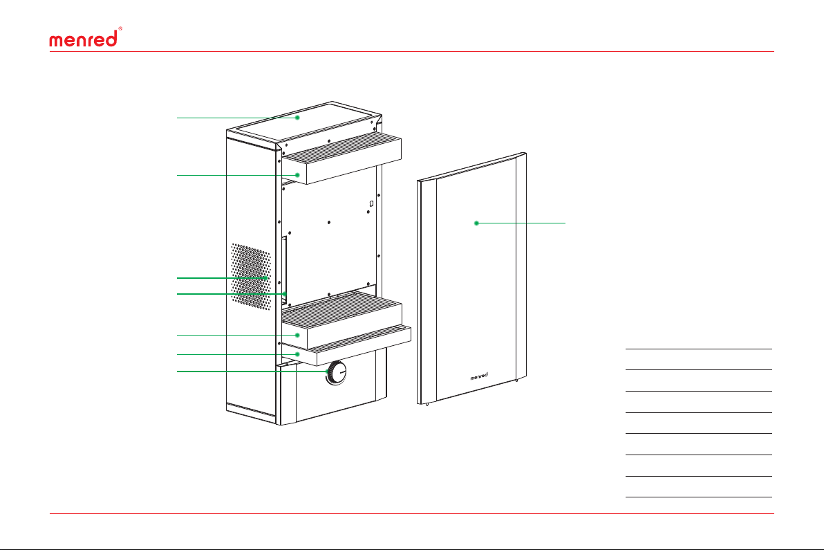
Medium efficiency filter
Primary efficiency filter
Rotary switch
High efficiency filter
Front panel
Return air inlet
Return air primary filter
Air outlet
Attention
menred central ventilator system
1.In order to use the ventilation equipment safely and reasonably, users and installers must read the instruction manual carefully.
2.MENRED ventilation equipment must be installed by professional technicians.
3.If users install the product by themselves, or by their own installation material, MENRED will not be responsible for any consequence
or loss (such as pipe leakage, machine crash, abnormal operation or use because of improper installation, damage etc.).
4.After the product is installed, users should check and maintain it often according to the service condition. Any abnormal condition,
please contact after-sales service department of local installation company to repair and make sure the product can operate normally,
safely and reliably.
5.Filters should be checked and replaced regularly. Users can contact local installation company to check and replace.
The recommended inspection period is 6 months.
6.Please cut off power before maintenance or repairing the product. Non-professionals should not adjust and repair products.
7.If the power cord is damaged, in order to avoid danger, it must be replaced by the professional technicians.
8.The equipment uses fixed wiring connection mode. Connect a switch with contact above 3mm space when installation.
9.After installation, users should test the equipment immediately to check if the product get damaged or not during the transportation.
10.The power outlet must have a reliable ground connection. It is prohibited using the outlet without a reliable ground connection.
CENTRAL VENTILATOR SYSTEM
02
www.menred.com

01
www.menred.com
CENTRAL VENTILATOR SYSTEM
Host
User Manual
Serial number
Bar code
Certificate of quality
Screws package
Wall pipe
1
1
2
2
1
1
2
Packing list
Unit(pcs)
Medium efficiency filter
Primary efficiency filter
Rotary switch
High efficiency filter
Front panel
Return air inlet
Return air primary filter
Air outlet
Attention
menred central ventilator system
1.In order to use the ventilation equipment safely and reasonably, users and installers must read the instruction manual carefully.
2.MENRED ventilation equipment must be installed by professional technicians.
3.If users install the product by themselves, or by their own installation material, MENRED will not be responsible for any consequence
or loss (such as pipe leakage, machine crash, abnormal operation or use because of improper installation, damage etc.).
4.After the product is installed, users should check and maintain it often according to the service condition. Any abnormal condition,
please contact after-sales service department of local installation company to repair and make sure the product can operate normally,
safely and reliably.
5.Filters should be checked and replaced regularly. Users can contact local installation company to check and replace.
The recommended inspection period is 6 months.
6.Please cut off power before maintenance or repairing the product. Non-professionals should not adjust and repair products.
7.If the power cord is damaged, in order to avoid danger, it must be replaced by the professional technicians.
8.The equipment uses fixed wiring connection mode. Connect a switch with contact above 3mm space when installation.
9.After installation, users should test the equipment immediately to check if the product get damaged or not during the transportation.
10.The power outlet must have a reliable ground connection. It is prohibited using the outlet without a reliable ground connection.
CENTRAL VENTILATOR SYSTEM
02
www.menred.com
03
www.menred.com
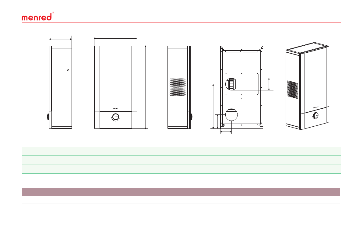
Performance parameter
Dimension
IT90 220/50 90 30 37 23
Model Power V/Hz)( 3
Air volume m /h)( Noise dB(A))(
Power W)( Weight kg)(
B
C
A
C
75 0
Outline dimension
IT 90
B
20 5
A
38 5
Note: if the design changes, the above data will be modified without prior notice. Please refer to the product for the exact size.
F
D
E
G
D
11 0
E
13 0
F
405
G
10 0
Repair and maintenance
Make sure that there is no obstacle within 50mm in the right
side of the machine when repairing and maintaining.
04
www.menred.com
Installation diagram
1.Press the installation board on the wall and draw the positions
of installation holes and screw holes.
2.Use the drill to punch the hole in the marked position by leaning
down 3°. The hole size should be greater than Ø120 but less than
Ø130. Then punch the screw holes by the drill with diameter Ø8
and put expansion screws.
3.Fix the mounting board on the wall by tapping screws.
4.Insert the wall pipe into the wall and the outdoor air vent should
be installed downwards. Tightening the fixing part clockwise, put
foaming agent in the four holes and cut off the redundant wall pipes.
5.Hang the machine on the mounting board and fix it by screws.
Unit(mm)

03
www.menred.com
Performance parameter
Dimension
IT90 220/50 90 30 37 23
Model Power V/Hz)( 3
Air volume m /h)( Noise dB(A))(
Power W)( Weight kg)(
B
C
A
C
750
Outline dimension
IT 90
B
205
A
385
Note: if the design changes, the above data will be modified without prior notice. Please refer to the product for the exact size.
F
D
E
G
D
110
E
130
F
405
G
100
Repair and maintenance
Make sure that there is no obstacle within 50mm in the right
side of the machine when repairing and maintaining.
04
www.menred.com
Installation diagram
1.Press the installation board on the wall and draw the positions
of installation holes and screw holes.
2.Use the drill to punch the hole in the marked position by leaning
down 3°. The hole size should be greater than Ø120 but less than
Ø130. Then punch the screw holes by the drill with diameter Ø8
and put expansion screws.
3.Fix the mounting board on the wall by tapping screws.
4.Insert the wall pipe into the wall and the outdoor air vent should
be installed downwards. Tightening the fixing part clockwise, put
foaming agent in the four holes and cut off the redundant wall pipes.
5.Hang the machine on the mounting board and fix it by screws.
Unit(mm)
05
www.menred.com
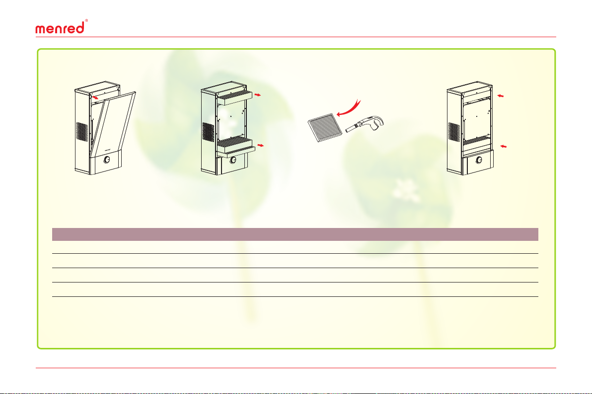
Filter element change
2.Take out the filter elements
in the direction of the figure.
4.Put the clean filter elements
into the corresponding slots
and close the front panel.
3.Clean the dust in the filter
by the vacuum cleaner or
change the filter element.
Primary efficiency filter: effectively block particles greater than PM10.
Medium efficiency filter: intercept particles with diameter above 2.5um, efficiently protect filters and prolong the high efficiency
filter working life.
High efficiency filter: efficiently filter PM2.5. Large dust capacity and low wind resistance.
Filter function introduction
G4
F9
H11
G4
Size(mm)
347x165x35
347x165x50
347x165x55
180x165x16
6
6
6
6
F167
F166
F165
F168
1.Open the front panel as
shown in the figure.
Wiring diagram
220V/50Hz
N
L
Panel open-power off switch
MC
Transformer
F
Speed switch
IN
OUT
Model Class Maintenance period(month) Maintenance method
06
www.menred.com
Rotary switch
When the switch is in the figure 1 position, the ventilator is in
closed state.
When the switch is in the figure 2 position, the ventilator is in
gear 1 and the air volume is 30m3/h.
When the switch is in the figure 3 position, the ventilator is in
gear 2 and the air volume is 50m3/h.
When the switch is in the figure 4 position, the ventilator is in
gear 3 and the air volume is 70m3/h.
When the switch is in the figure 5 position, the ventilator is in
gear 4 and the air volume is 90m3/h.
Figure 1 Figure 2 Figure 3
Figure 4 Figure 5
Filter position
Primary efficiency filter
Medium efficiency filter
High efficiency filter
Return air primary filter
Change
Change
Change
Change

05
www.menred.com
Filter element change
2.Take out the filter elements
in the direction of the figure.
4.Put the clean filter elements
into the corresponding slots
and close the front panel.
3.Clean the dust in the filter
by the vacuum cleaner or
change the filter element.
Primary efficiency filter: effectively block particles greater than PM10.
Medium efficiency filter: intercept particles with diameter above 2.5um, efficiently protect filters and prolong the high efficiency
filter working life.
High efficiency filter: efficiently filter PM2.5. Large dust capacity and low wind resistance.
Filter function introduction
G4
F9
H11
G4
Size(mm)
347x165x35
347x165x50
347x165x55
180x165x16
6
6
6
6
F167
F166
F165
F168
1.Open the front panel as
shown in the figure.
Wiring diagram
220V/50Hz
N
L
Panel open-power off switch
MC
Transformer
F
Speed switch
IN
OUT
Model Class Maintenance period(month) Maintenance method
06
www.menred.com
Rotary switch
When the switch is in the figure 1 position, the ventilator is in
closed state.
When the switch is in the figure 2 position, the ventilator is in
gear 1 and the air volume is 30m3/h.
When the switch is in the figure 3 position, the ventilator is in
gear 2 and the air volume is 50m3/h.
When the switch is in the figure 4 position, the ventilator is in
gear 3 and the air volume is 70m3/h.
When the switch is in the figure 5 position, the ventilator is in
gear 4 and the air volume is 90m3/h.
Figure 1 Figure 2 Figure 3
Figure 4 Figure 5
Filter position
Primary efficiency filter
Medium efficiency filter
High efficiency filter
Return air primary filter
Change
Change
Change
Change
Table of contents
Popular Fan manuals by other brands


Vortice
Vortice VORT HR 300 NETI Instruction booklet

Vaventis
Vaventis Fresh-r On-The-Wall Maintenance manual

Ebmpapst
Ebmpapst W2G107-AD03-02 operating instructions

Ebmpapst
Ebmpapst R2E250-AS47-09 operating instructions

Ebmpapst
Ebmpapst W3G800-GO84-01 operating instructions

System air
System air fantech bathfan Select Fit SF Series Installation, operation and maintenance instructions