SpeedComfort Trio Set User manual
Installation and
User Instructions
February 2021
Version 03.00

Disclaimer
SpeedComfort makes no representations or warranties with respect to this manual and, to the maximum
extent permitted by law, expressly limits its liability for breach of any warranty that may be implied to
the replacement of this manual with another. Furthermore, SpeedComfort reserves the right to revise
this publication at any time without incurring an obligation to notify any person of the revision.
The information provided in this documentation contains general descriptions and technical
characteristics of the performance of the products contained herein. This documentation is not intended
as a substitute for and is not to be used for determining suitability or reliability of these products
for specic user applications. Neither SpeedComfort nor any of its aliates or subsidiaries shall be
responsible or liable for misuse of the information that is contained herein. If you have any suggestions
for improvements or amendments or have found errors in this publication, please notify us.
Failure to observe this information can result in injury or equipment damage.
Copyright © 2021 by SpeedComfort
All rights reserved. No part of this publication may be reproduced, distributed, or transmitted in any
form or by any means, including photocopying, recording, or other electronic or mechanical methods,
without the prior written permission of the manufacturer. For permission requests, write to the
publisher, addressed “Attention: Permissions Coordinator,” at the address below.
SpeedComfort
Antwoordnummer 7200
3734 ZW Den Dolder
The Netherlands
Tel: +31 85 666 62 23
Email: info@speedcomfort.com
Website: www.speedcomfort.com

3
Table of Contents
1. Preface 4
1.1. Description of the User 4
1.2. Conventions Used in this Manual 4
1.3. Explanation of Safety Warnings 4
1.4. Retaining Instructions 4
1.5. Obtaining Documentation and Information 5
2. Description of the Product 6
2.1. Intended Use and Reasonably Foreseeable Misuse 6
2.2. System Overview 6
2.3. Technical Data 7
2.4. Main components 8
3. Safety Instructions 9
3.1. How to Use the Product Safely 9
4. Installation 11
4.1. Determine the type of your radiator 11
4.2. Connect the SpeedComfort to the Radiator 12
4.3. Optimize the Central Heating 18
5. Maintenance 19
5.1. How to Maintain the SpeedComfort 19
6. Troubleshooting 20
7. Disposal 23
7.1. Disposal of the Product 23
7.2. Disposal of Packaging Waste 23

1. Preface
1.1. Description of the User
This installation manual is intended for the end-user, the general homeowner, who wants to
install one or more SpeedComforts on the radiators in his home. The user does not need to
be skilled, trained or certied to install the SpeedComfort.
1.2. Conventions Used in this Manual
The following style conventions are used in this document:
Bold
Names of product elements
Italic
Emphasis (for example a new term)
1.3. Explanation of Safety Warnings
Caution indicates a hazard with a low level of risk which, if not avoided, could result in minor
or moderate injury.
Notice indicates information considered important, but not hazard-related.
1.4. Retaining Instructions
Read and understand this manual and its safety instructions before using this product.
Follow all the instructions. This will avoid re, explosions, electric shocks or other hazards
that may result in damage to property and/or injuries.
The product shall only be used by persons who have fully read and understand the contents
of this user manual.

5
Ensure that each person who uses the product has read these warnings and instructions and
follows them.
Keep all safety information and instructions for future reference and pass them on to
subsequent users of the product.
The manufacturer is not liable for cases of material damage or personal injury caused
by incorrect handling or non-compliance with the safety instructions. In such cases, the
warranty will be voided.
1.5. Obtaining Documentation and Information
1.5.1. Internet
The latest version of the documentation is available at the following address:
https://www.speedcomfort.nl/media/downloads/SpeedComfort_manual.pdf
1.5.2. Ordering documentation
Documentation, user instructions and technical information can be ordered by calling
SpeedComfort at +31 85 666 62 23.
1.5.3. Documentation feedback
If you are reading SpeedComfort product documentation on the internet, any
comments can be submitted on the support website. Comments can also be sent to
UKsupport@speedcomfort.com.
We appreciate your comments.
1.5.4. Support and service
For information, questions, technical assistance, service or ordering user instructions please
contact:
SpeedComfort
Antwoordnummer 7200
3734 ZW Den Dolder
The Netherlands
Tel: +31 85 666 62 23
Website: www.speedcomfort.com

2. Description of the Product
2.1. Intended Use and Reasonably Foreseeable Misuse
The SpeedComfort is intended to be used as a ventilator that is intended to be attached to a
radiator or convector, which is connected to the central heating system. The SpeedComfort is
intended to draw heat from the radiator to help heat the room more eectively.
The product may only be used in accordance with the instructions described in this manual.
Any use other than those described in this manual is considered as non-intended use. This
will also invalidate the warranty.
2.2. System Overview
This product contains several components that form a system.
The SpeedComfort is the main component. The SpeedComfort is connected to a power
adapter and a temperature sensor. For a wide radiator (plates 70mm or more apart) this is
all that is needed, except for some optional cables. For other radiators, simply reposition the
magnetic sliders or feet:
•For a narrow radiator (plates less than 70mm apart), position the magnetic sliders
with the magnet facing upwards, two on each side.
•For a single plate radiator, position the magnetic sliders with all four on one side
and the magnet facing up.
•For a convector, position the four integrated feet in the holes provided on the
underside of the SpeedComfort.
Additional SpeedComforts can be connected to each other making use of the cables (30cm,
60cm or 120cm). These cables can also be used to extend the power adapter or temperature
sensor cables.

7
2.3. Technical Data
Parameter Unit
Product name SpeedComfort
Technical lifespan: SpeedComfort 10 years
Technical lifespan: Power adapter 4 years
Power 0.55 W
Annual energy consumption < 1 kWh
Noise level < 20 dB(A)
Airow 30 m3/hour
Width x length 7cm x 34cm
Output 12 V/DC
Power supply 100-240V; 0.25A 230V AC
Operating temperature range -20°C to +85°C
Storage temperature range -40 °C to +85°C
Relative humidity during use and storage max. 80% (non-condensing)
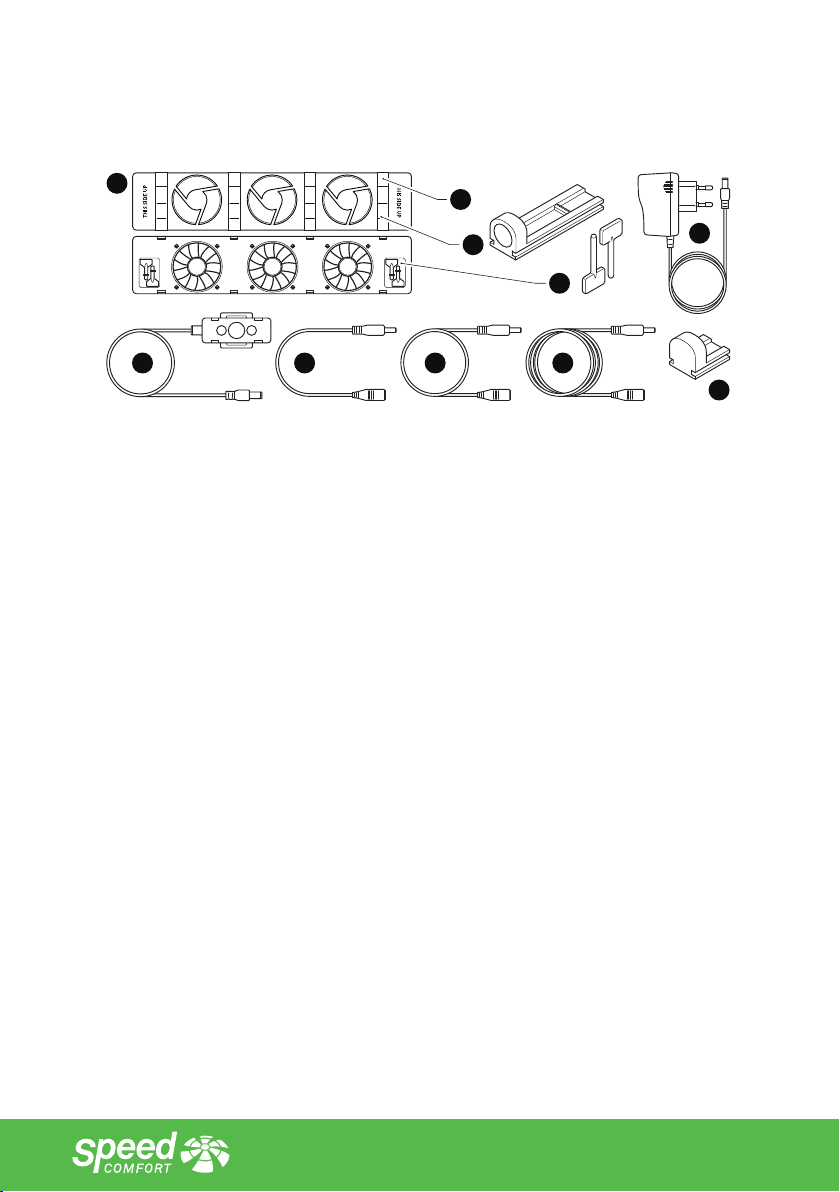
2.4. Main components
D
E F G H
I
A
C
B
I
A. SpeedComfort
B. Adjustable magnets (4x)
C. Feet (4x)
D. Power adapter
E. Temperature sensor (with Velcro)
F. Connecting cable (included with Duoset, Trioset and Extension Set)
G. 60 cm cable (optional)
H. 120cm cable (optional)
I. Dummy blocks (4x - without function)

9
3. Safety Instructions
Read and understand this manual and its safety instructions before using the
SpeedComfort and matching components.
3.1. How to Use the Product Safely
3.1.1. Safety information for vulnerable people
•Never leave children alone with packaging material. There is a risk of
suocation.
•Children should not play with the product. This product is not a toy.
•Do not install the product if you have reduced physical, sensory or mental
capabilities.
•Do not allow installation of the product by persons (including children) with
reduced physical, sensory or mental capabilities.
3.1.2. Safety information related to the intended use
•Use this product only as a radiator ventilator by attaching it to a radiator. Follow
the instructions in this manual to do so.
3.1.3. Product limitations and restrictions
•Do not use any sharp objects near the fans.
•Keep the product away from open re, soldering irons, or other hot tools as this
could damage the product.
3.1.4. Installation safety information
•Lift, handle and transport the product with great care.
•Pay attention and be careful when installing an electrical product. Do not
install the product if you are not able to concentrate properly, or if you may
faint or if you are under the inuence of medication, alcohol or drugs.
•Before connecting the power adapter to the wall socket, ensure that the local
voltage corresponds to the value on the product. The maximum permissible
voltage is 230V.
•Connect the product to a properly installed and easily accessible wall socket.
Make sure the product can be disconnected from the power supply at any time.

3.1.5. Safety information regarding the use
•Never use the product outdoors. The product is intended for indoor use only.
•Check all components (including cables) for any damages before installing the
product. Immediately remove the power adapter from the wall socket in the
event of visible damage, strong odour or overheating of the components.
3.1.6. Maintenance safety information
•Never touch the product or power adapter with wet hands.
•Keep the product away from moisture. Take care when cleaning the product or
radiator to which it is attached. Make sure no water enters the product through
the fans.
3.1.7. Service and repair safety information
•Do not attempt to open, modify or repair the product. Alterations or
modications of this product are not permitted. This will void the warranty.

11
4. Installation
4.1. Determine the type of your radiator
The SpeedComfort can be installed on dierent types of radiators. Each type of radiator
requires its own way of installation.
Determine the type of your radiator:
1. Determine the radiator types on which you want to install the SpeedComfort.
1 2
3 4
≥ 70 mm <70 mm
This is a radiator where the distance between the plates is 70mm or more.
Narrow radiators are radiators where the distance between the plates is less
than 70mm.
Single plate radiators are radiators with only one plate.
Convectors are radiators where the hot water is circulated through a tube,
surrounded by small ns. It is normally installed inside a convector housing or
a convector duct.

4.2. Connect the SpeedComfort to the Radiator
The SpeedComfort can be installed on dierent types of radiators. Each type of radiator
requires its own way of installation. Follow the specic installation steps for this type of
radiator.
4.2.1. Connect the SpeedComfort to a wide radiator (plates ≥ 70mm apart)
1. Make sure that the SpeedComfort (A) faces upwards and that the female
connectors (1) point towards the wall socket (see g.1).
≥ 70mm
A
1
Fig.1 - Position the SpeedComfort (A).
13
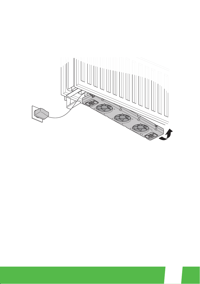
2. Identify a space where the radiator wall brackets and connecting clips are not in
the way. Attach the SpeedComfort (A) at the bottom between the radiator plates
with the adjustable magnets (B) (see g.2). The SpeedComfort (A) can also be
attached on top of the radiator and under a cover. NOTICE Make sure the fans still
face upwards!
Fig.2 - Attach the SpeedComfort (A).
3. Connect the temperature sensor cable (E) to one of the SpeedComfort (A)
female connectors (1).
4. Attach the temperature sensor (E) with its adjustable magnets (B) on the back of
the radiator, close to the warm water supply pipe, or on the pipe itself (see g.3).
Adjust the magnetic sliders to the correct width.
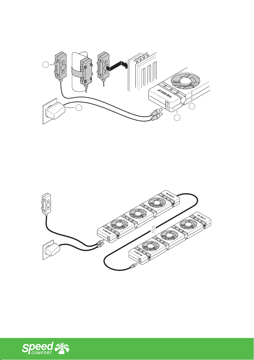
5. Connect the power adapter (D) to the remaining female connector (1) and the
wall socket (see g.3).
D
E
A
1
Fig.3 - Connect the power adapter (D) and temperature sensor (E).
6. On long radiators, connect additional SpeedComforts (A) with the 30cm
connecting cables (F) (see g.4). Multiple SpeedComforts (A) (up to 20) can be
connected to one power adapter (D). Additional temperature sensors (E) are not
required. The Duoset and the Trioset include several SpeedComforts.
Fig.4 - Connect additional SpeedComforts (A).
7. Turn on your central heating system. Wait for the SpeedComfort (A) to
automatically switch on. This happens when the radiator temperature exceeds
33°C. It automatically switches o when the radiator cools down to 25°C.

15
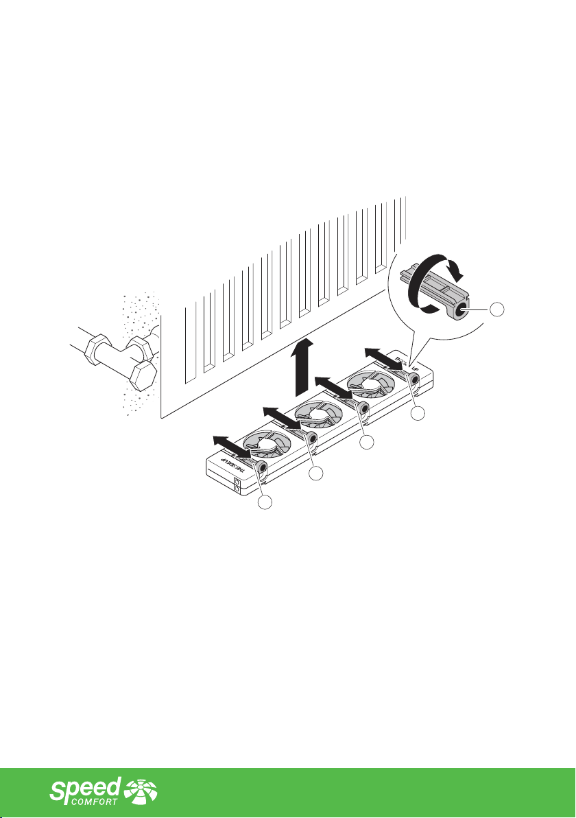
4.2.2. Connect the SpeedComfort to a narrow radiator (plates < 70mm apart)
1. Turn the adjustable magnets (B) until the magnet (1) is on top (see g.5). Remove
the small block located opposite to the adjustable magnets in the housing. Please
dispose of the block as plastic waste.
2. Adjust the adjustable magnets (B) to the correct width.
3. Repeat step 1 – 7 as for the wide radiator. Use the adjustable magnets (B) to hang
the SpeedComfort (A) between the plates (see g.5 and 6). You can align the
SpeedComfort on the front of the radiator.
B
B
B
B
1
Fig.5 - Return the adjustable magnets into the SpeedComfort (A).
Fig.6 - Hang the SpeedComfort (A) between radiator plates.
4.2.3. Connect the SpeedComfort to a Single plate radiator
1. Position the adjustable magnets (B) until the magnets (1) are on the same side
and all four magnets (1) are facing up. Remove the small block located opposite to
the adjustable magnets in the housing. Please dispose of the block as plastic waste.
2. Repeat step 1 – 7 as for the wide radiator.
3. Use the adjustable magnets (B) to attach the SpeedComfort (A) to the single plate
radiator (see g.7).
1
B
B
B
B
Fig.7 - Attach the SpeedComfort (A) to a single plate radiator.
4.2.4. Connect the SpeedComfort to a convector
1. Attach the feet (C) by pushing them into the slots (2) of the SpeedComfort (A).
2. Make sure that the SpeedComfort (A) faces upwards and that the female
connectors (1) point towards the wall socket (see g.9).
3. Place the SpeedComfort (A) on top of the convector and allow space between
the convector sides and the SpeedComfort (A) to reduce noise (see g.9). The
SpeedComfort can also be placed on the ground below the convector if space
allows.

17
4. If the convector block is made of magnetic material, the temperature sensor (E)
can be easily positioned on it with its magnets. The temperature sensor can also be
clamped between two plates of the convector block to ensure good heat transfer.
The sensor can be attached to a copper pipe or any other non-magnetic location
using the provided Velcro.
Fig.8 - Attach a foot (C).
Fig.9 - Position the SpeedComfort (A) on the convector.
4 × C
2
1
A

4.3. Optimize the Central Heating
The SpeedComfort draws heat from the radiator, heating the room quicker and more evenly.
This can reduce the energy usage in your house by up to 22%. However, to realize this saving,
a few things need to be optimized: The SpeedComforts must be distributed throughout the
house; the central heating temperature setpoint must be lowered; and the central heating
system must be hydronically balanced.
4.3.1. Distribute the SpeedComforts
1. Install 3 to 5 SpeedComforts (A) (with matching components) in an (average)
living room.
2. Install SpeedComforts (A) in all regularly used rooms.
This ensures that all the air in the room circulates once per hour (since one SpeedComfort
circulates 30m3/h).
4.3.2. Lower the temperature setpoint
1. Manually lower the central heating setpoint temperature to at least 60°C. Refer to
the manual of your central heating system or ask your service technician to do this.
If preferred, this can be done in small steps to nd the optimal setpoint. A lower
setpoint saves more energy.
2. Make sure your central heating service technician does not change this back to
factory settings (75 – 90°C).
The SpeedComfort draws heat from the radiator, heating the room more quickly. This allows
the boiler to shut down sooner, saving energy.
4.3.3. Hydronic balancing
Balance the central heating system by making use of either the radiator screw, standard
thermostat setting or a separate radiator valve. CAUTION!
Ask the central heating service technician to help with the central heating system hydronic
balancing. This is not a standard procedure and requires expertise.
Hydronic balancing optimizes the distribution of water in a heating system. This is necessary
for ecient use of energy and to ensure that room temperatures do not vary.
To learn more about saving energy and reducing losses visit: www.speedcomfort.com.

19
5. Maintenance
5.1. How to Maintain the SpeedComfort
5.1.1. Cleaning the product
The SpeedComfort and matching components can be cleaned if necessary.
To clean the product:
1. Clean the product with a vacuum cleaner, when dirty. CAUTION! Make sure to use
the lowest power setting on the vacuum cleaner.
2. Clean the product with a damp cloth only if required. CAUTION! Make sure no
water enters the SpeedComfort through the fans.
5.1.2. Replacing components
If any components break, they must be replaced. CAUTION! Do not attempt to open, modify
or repair the product.
To replace components:
1. Exchange broken components, still under warranty, at the supplier. The
SpeedComfort has a ten year guarantee and the power adapter has a 2 year
warranty. NOTICE For safety- and control reasons (CE), alterations or modications
of this product are not permitted.
2. Dispose of broken components that are not under warranty and buy new
components.

6. Troubleshooting
Problem Cause Solution
SpeedComfort (A)
does not t between
the radiator plates.
It is a narrow radiator. Follow the installation steps for
Speedcomfort with a narrow radiator.
SpeedComfort
(A) does not t at
the bottom of the
radiator.
There is too little space. Place the SpeedComfort (A) on top
of the radiator. This will not inuence
performance. The bottom is only
preferred as it is less visible. Make
sure the SpeedComfort (A) still faces
upwards.
The SpeedComfort
(A) need to be
attached at the top of
the radiator, but the
radiator has a cover.
NA Place the SpeedComfort (A)
underneath the cover. Keep in mind
that this exposes the SpeedComfort
(A) to higher temperatures, which
may slightly limit its lifespan.
Cannot connect the
SpeedComfort (A) to
the wall socket.
The SpeedComfort (A)
was placed with the two
female connections on
the wrong side or the
power adapter cable (D)
is not long enough.
Turn the SpeedComfort (A) around
so that the two female connections
face in the other direction or buy and
connect the power adapter cable
(D) to a longer cable (G or H).
Cannot connect two
SpeedComforts
(A) with the
supplied 30cm long
connecting cable (F).
The distance is too big /
cable is too short.
Buy an additional 60cm or 120cm
long cable (G or H) to connect the
SpeedComforts (A).
The temperature
sensor (E) cannot
reach the warm water
supply pipe.
The temperature sensor
cable is too short.
Buy an additional 60cm or 120cm
long cable (G or H) and connect to
the temperature sensor cable. Else,
the temperature sensor (E) may
also be attached on the back of the
radiator.
Table of contents
Popular Fan manuals by other brands


System air
System air MUB-EC Series Installation and operating instructions

Ebmpapst
Ebmpapst W3G630-DQ37-35 operating instructions

TriStar
TriStar VE-5933 instruction manual

Ebmpapst
Ebmpapst R1G175-AF29-04 operating instructions

Ebmpapst
Ebmpapst K3G310-AV52-06 operating instructions

Ebmpapst
Ebmpapst DV5214 N operating manual