GE BF230UQ User manual

a
BF230UQ, BF270UQ, BF375UQ
e
Ultra Quiet Bath Fan User’s Guide
210572117 Rev. B 5-06
Item Stock Number(s): BF230UQ, BF270UQ, BF375UQ
READ AND SAVE THESE INSTRUCTIONS
READ CAREFULLY BEFORE ATTEMPTING TO ASSEMBLE, INSTALL, OPERATE OR MAINTAIN THE PRODUCT DESCRIBED.
PROTECT YOURSELF AND OTHERS BY OBSERVING ALL SAFETY INFORMATION. FAILURE TO COMPLY WITH
INSTRUCTIONS COULD RESULT IN PERSONAL INJURY AND/OR PROPERTY DAMAGE!
RETAIN INSTRUCTIONS FOR FUTURE REFERENCE.
GENERAL SAFETY INFORMATION
When using electrical appliances, basic precautions should always be followed to reduce
the risk of fire, electric shock and injury to person, including the following:
1. Read all instructions before installing or using
exhaust fan.
2. Use this unit only in the manner intended by the
manufacturer. If you have questions, contact the
manufacturer.
3. Before servicing or cleaning the unit, switch power
off at service panel and lock the service disconnecting
means to prevent power from being switched on
SAVE THESE INSTRUCTIONS
IMPORTANT INSTRUCTIONS -
OPERATING MANUAL
accidentally. When the service disconnecting means
cannot be locked, securely fasten a prominent warning
device, such as a tag, to the service panel.
4. Installation work and electrical wiring must be done
by qualified person(s) in accordance with all applicable
codes and standards, including fire-related construction.
5. Sufficient air is needed for proper combustion and
exhausting of gases through the flue (chimney) of
1 of 8
www.geelectrical.com

210572117 Rev. B 5-06
GENERAL SAFETY INFORMATION
(Continued)
fuel burning equipment to prevent back drafting. Follow
the heating equipment manufacturer’s guideline and
safety standards such as those published by the National
Fire Protection Association (NFPA) and the American
Society for Heating, Refrigeration, and Air Conditioning
Engineers (ASHRAE), and the local code authorities.
CAUTION: FOR GENERAL VENTILATING USE
ONLY. DO NOT USE TO EXHAUST HAZARDOUS OR
EXPLOSIVE MATERIALS AND VAPORS.
6. When cutting or drilling into wall or ceiling, do not
damage electrical wiring and other hidden utilities.
7. Ducted fans must always be vented to the outdoors.
8. This unit must be grounded.
9. To avoid motor bearing damage and noisy and/or
unbalanced impellers, keep drywall spray, construction
dust, etc. off power unit.
WARNING: TO REDUCE THE RISK OF FIRE,
ELECTRIC SHOCK, DO NOT USE THIS FAN WITH ANY
SOLID-STATE SPEED CONTROL DEVICE.
10. Acceptable for use over a bathtub or shower when
installed in a GFCI protected branch circuit.
11. NEVER place a switch where it can be reached from
a tub or shower.
WARNING: DO NOT USE IN KITCHENS
INSTALLATION INSTRUCTIONS
CAUTION: MAKE SURE POWER IS SWITCHED OFF
AT SERVICE PANEL BEFORE STARTING INSTALLATION.
SECTION 1
Preparing the Exhaust Fan
1. Unpack fan from the carton and confirm that all
pieces are present. In addition to the exhaust fan
you should have:
1 - Grill
1 - Damper Assembly (attached)
2 - Mounting Brackets
1 - Mounting Flange
4 - 10-32 Nuts
1 - Instruction/Safety Sheet
2. Choose the location for your fan. To ensure the best
air and sound performance, it is recommended that
the length of ducting and the number of elbows be
kept to a minimum, and that insulated hard ducting
be used. Larger duct sizes will reduce noise and
airflow restrictions. This fan will require at least 10"
of clearance in the ceiling or
wall, and will mount through
drywall up to 3/4" thick.
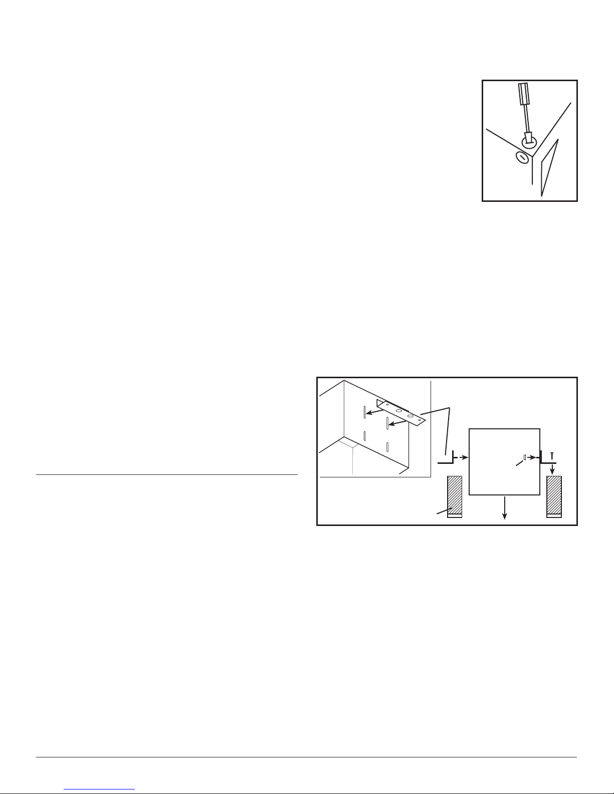
3. Select the most convenient
electrical knockout and
remove using a straight-blade
screw driver (Figure 1).
SECTION 2
Mounting the Housing
1a. Installation on 2x4 Joists on 16" Centers: Install the
mounting brackets through the second set of slots
on the fan housing and secure in place with the four
included #10-32 nuts as shown. Center the fan
housing between the joists and secure the mounting
brackets with screws or nails (not included) to the
joist. Adjust the height of the housing so that it is
flush with the finished ceiling by loosening the
mounting bracket nuts and sliding the housing up or
down on the bracket. Full tighten all four nuts to
secure the housing in place (Figure 2).
1b. Installation on 2x6 Joists on 16" Centers: Install the
mounting brackets through the second set of slots
on the fan housing and secure in place with the four
included #10-32 nuts as shown. Center the fan housing
between the joists and secure the mounting brackets
with screws or nails (not included) to the joist. Adjust
the height of the housing so that it is flush with the
finished ceiling by loosening the mounting bracket
nuts and sliding the housing up or down on the
bracket. Fully tighten all four nuts to secure the
housing in place (Figure 3).
Figure 1
Figure 2 Joist
Housing
Bracket
Nut
2 of 8
www.geelectrical.com

210572117 Rev. B 5-06
1c. Installation on 24" Centers Joists or Larger than 2x6
Joists on 16" Centers: Install two - 2x4 headers (not
included) between the joists (Figure 4). Install the
mounting brackets through the top set of slots on
the fan housing and secure in place with the four
included #10-32 nuts as shown. Position the fan
housing between the headers and secure the
mounting brackets with screws or nails (not included)
to the header. Adjust the height of the housing so
that it is flush with the finished ceiling by loosening
the mounting bracket nuts and sliding the housing
up or down on the bracket. Fully tighten all four nuts
to secure the housing in place (Figure 5).
SECTION 3
Ducting
CAUTION: ALL DUCTING MUST COMPLY WITH
LOCAL AND NATIONAL BUILDING CODES.
1. Connect the ducting to the fan’s duct collar (Figure
6). Secure in place using tape or screw clamp. Always
duct the fan to the outside through a wall or roof cap.
SECTION 4
Wiring
CAUTION: MAKE SURE POWER IS SWITCHED OFF
AT SERVICE PANEL BEFORE STARTING INSTALLATION.
CAUTION: ALL ELECTRICAL CONNECTIONS MUST
BE MADE IN ACCORDANCE WITH LOCAL CODES,
ORDINANCES, OR NATIONAL ELECTRICAL CODE. IF YOU
ARE UNFAMILIAR WITH METHODS OF INSTALLING
ELECTRICAL WIRING, SECURE THE SERVICES OF A
QUALIFIED ELECTRICIAN.
NOTE: This unit includes a side access panel for wiring
that does not require the removal of the fan’s blower
assembly. If you choose to wire the unit from the inside,
you will need to remove the blower assembly and internal
wiring compartment. Both methods are equally effective.
1a. External Wire Compartment: Remove the wire
compartment cover screw and place cover in a
secure place (Figure 7).
1b. Internal Wire Compartment: Using a 7/16" socket,
remove the two hex nuts holding the blower assembly
in place. Lift up on the assembly and slide it out of
the tabs on the housing (Figure 8). Remove the wire
compartment cover screw and place the cover in a
secure place (Figure 9).
Figure 3 Joist
Housing
Bracket
Nut
Figure 5 Header
Housing
Bracket
Nut
Figure 4
Joist
2 x 4 Header
Joist
2 x 4 Header
Ceiling
Figure 7
Screw
Wire
Compartment
Cover
Ducting
Duct
Collar
Figure 6
3 of 8
www.geelectrical.com

Figure 8
Plug
Hex Nuts
Tabs
Figure 11
210572117 Rev. B 5-06
NOTE: If the fan motor plug is connected to the fan
housing receptacle, unplug so the blower assembly can
be completely removed.
2. Run wiring from an approved wall switch carrying the
appropriate rating. One neutral (white), one ground
(green or bare copper), and one hot (black lead
connected to the switch). Secure the electrical wires
to the housing with an approved electrical connector.
Make sure you leave enough wiring in the box to make
the connection to the fan’s receptacle.
3. From where you have chosen to access the fan’s
junction box, connect the white wire from the house
to the white wire from the fan’s receptacle. Connect
the black wire from the wall switch to the black wire
from the fan’s receptacle. Connect the ground wire
from the house to the green wire from the fan housing
(Figure 10). Use approved methods for all connections.
NOTE: The fan’s receptacle wires might need to be pulled
outside compartment for connection. Only pull the three
loose wires outside of compartment. Additional wires
will be present.
Screw
Wire Compartment
Cover
Figure 9
4. Carefully tuck wire back inside wire compartment
and replace wire compartment cover securing with
the screw that was removed earlier.
SECTION 5
Completing the Installation
1. If the fan’s blower assembly was removed during
the wiring process, reinstall the blower by reversing
the directions in Section 4 (Wiring)
, Step 1b
.
2. Plug the fan’s quick connect motor cord into the
receptacle. This cord will only fit one way into the
receptacle (Figure 11).
3. Install the ceiling mounting flange to cover any gaps
which exist between the housing and the finished
ceiling. Line up the slots in the ceiling mounting
flange with the screws on the inside of the housing
and press flange in place so it is tight against the
ceiling. Tighten both screws inside the housing.
Install drywall screws (not included) through the
holes in the flange and into the ceiling. Install as
many drywall screws needed to ensure the flange
fits tightly against the ceiling (Figure 12).
4. Install the grill by squeezing the two ends of the
springs together and installing them up into the slots
on the fan’s housing. Push the grill up into position
(Figure 13).
Ground
Hot (Black)
White
Supply from
house
Figure 10 Figure 12 Drywall Screw
Ceiling
Mounting
Flange Slots
Screws
4 of 8
www.geelectrical.com

Troubleshooting Guide
Trouble Probable Cause Suggested Remedy
1. Fan does not operate when the switch is on. 1a. A fuse may be blown or a circuit tripped. 1a. Replace fuse or reset circuit breaker.
1b. Connector plug from motor is not plugged in. 1b. Turn off power to unit. Remove Grill and plug motor into
receptacle in housing. Restore power to unit.
1c. Wiring is not connected properly. 1c. Turn off power to unit. Check that all wires are connected.
2. Fan is operating, but air moves slower than normal. 2. Obstruction in the exhaust ducting. 2. Check for any obstructions in the ducting. The most common
are bird nests in the roof cap or wall cap where the fan
exhausts to the outside.
3. Fan is operating louder than normal. 3a. Motor is loose. 3a. Turn off power to unit. Remove grill and check that all screws
are fully tightened. Restore power to unit.
3b. Fan blade is hitting housing of unit. 3b. Call your dealer for service.
Figure 13
210572117 Rev. B 5-06
5. Restore power and test your installation.
SECTION 6
Use and Care
CAUTION: MAKE SURE POWER IS SWITCHED
OFF AT SERVICE PANEL BEFORE SERVICING THE UNIT.
1. Cleaning the Grill: Remove grill and use a mild
detergent, such as dishwashing liquid, and dry with
a soft cloth. NEVER USE ANY ABRASIVE PADS OR
SCOURING POWDERS. Completely dry grill before
reinstalling. Refer to instructions in Section 5
Finishing the Installation
, to reinstall grill.
2. Cleaning the Fan Assembly: Wipe all parts with a
dry cloth or gently vacuum the fan. NEVER IMMERSE
ELECTRICAL PARTS IN WATER.
5 of 8
www.geelectrical.com

WARRANTY
WHAT IS COVERED?
Full Five Year Parts Warranty from date of original proof of
purchase. We will provide, free of charge, a replacement part
that fails due to manufacturing defect in material or workmanship,
when installed and used as directed in the User’s Guide.
This warranty is extended to the original purchaser for products
purchased for ordinary home use.
Read your User’s Guide. If you have any questions about operating the product, please contact your dealer.
Some states and provinces do not allow the exclusion or limitation of incidental or consequential damages and some states
do not allow limitations on how long an implied warranty lasts, so these exclusions or limitations may not apply to you. This
warranty gives you specific legal rights and you may have other rights which vary from state to state and province to province.
WHAT IS NOT COVERED?
• Installation services or service trips to your home to teach
you how to use the product.
• Labor costs or the cost of replacement components as part
of routine maintenance.
• Failure or defects in product arising from Improper installation
If you have an installation problem, contact your dealer or
installer. You are responsible for providing adequate
electrical, exhausting and other connecting facilities. See
the Installation Instructions provided with this product for
electrical, exhaust and connection details.
• Replacement of house fuses or resetting of circuit breakers.
• Failure of the product if it is used for something other than
the intended purpose of manufacturer or used commercially.
• Damage to the product caused by accident, fire, floods,
acts of customer, or acts of God.
This warranty contains the sole and exclusive warranty of GE for claims based on defects in these products. Upon the expiration
of the warranty period, all such liability shall terminate. There are no other warranties, whether written, oral, implied or
statutory. NO IMPLIED STATUTORY WARRANTY OF MERCHANTABILITY OR FITNESS FOR PARTICULAR PURPOSE SHALL APPLY.
IN NO EVENT SHALL GE BE LIABLE FOR ANY SPECIAL, CONSEQUENTIAL, INDIRECT, OR INCIDENTAL DAMAGES, SUCH AS, BUT
NOT LIMITED TO, LOSS OF PROFIT OR REVENUES, LOSS OF USE OF THE PRODUCTS OR ANY ASSOCIATED EQUIPMENT, DAMAGE
TO ASSOCIATED EQUIPMENT, OR COST OF SUBSTITUTE PRODUCTS.
IN NO EVENT, SHALL GE’S LIABILITY TO BUYER FROM THE SALE OF THESE PRODUCTS EXCEED THE PRICE OF THE DEFECTIVE
PRODUCT SOLD AND ANY SUCH LIABILITY SHALL TERMINATE UPON THE EXPIRATION OF THE WARRANTY PERIOD.
210572117 Rev. B 5-06 6 of 8
www.geelectrical.com

210572117 Rev. B 5-06
# Qty. Description Replacement Part #
1 1 Fan Housing 5S1202044
2 2 Mounting Bar 5S1202045
3 4 Nuts 5S1202041
4 1 Metal Collar 5S5202007
5 2 Bushing 5S5202003
6 1 Spring 5S5202008
7 2 Damper 5S5202009
8 1 Rod 5S5202010
9 2 Grill Springs 5S1202046
10 1 Grill 5S1202048
11 2 Flange Screw 5S1202049
12 1 Ceiling Flange 5S1202050
13 2 Nuts 5S1202031
14 2 Blower Grommet 5S1202032
15 1 Blower Housing 5S2202022
16 1 Blower Wheel 5S2202023
12
2
3
3
4
5
6
7
8
9
10
11
12
13
14
15
16
17
18
19
20
21
22
23
24
25
26
27
24
28
29
24
REPLACEMENT PARTS DIAGRAM
# Qty. Description Replacement Part #
17 1 Nut 5S2202014
18 1 Motor - 210 CFM 5S2202024
1 Motor - 310 CFM 5S2202025
19 1 Motor Plate 5S2202020
20 3 Screw 5S2202027
21 5 Screw 5S2202017
22 1 Motor Cap Harness - AK200LS 5S2202010
1 Motor Cap Harness - AK300LS 5S1202051
23 1 Internal Wire Cover 210 CFM 5S1202004
1 Internal Wire Cover - 310 CFM 5S1202052
24 6 Screw 5S1999010
25 1 Outlet Gasket 5S1202053
26 1 Collar Gasket 5S1202054
27 1 External Wire Cover 5S1202007
28 1 14 ga Ground Wire 5S1999003
29 1 #10 Ground Screw 5S1999002
7 of 8
www.geelectrical.com

210572117 Rev. B 5-06 8 of 8
Table of contents
Other GE Fan manuals
Popular Fan manuals by other brands

Klimawent
Klimawent BULLET-160-N Use and maintenance manual

Kendal Lighting
Kendal Lighting AC-24060 installation instructions

Rowan Elettronica
Rowan Elettronica 5314 instruction manual

FACTO
FACTO F-1630 Operator's manual

AERMEC
AERMEC Omnia ULI PC Series Use and installation manual

Ensy
Ensy InoVent AHU-200 Series manual