Merco FFHS 27000 Series User manual

FFHSserviceman REV: 11/10/08
SERVICE MANUAL
(DOMESTIC & INTERNATIONAL)
FRIED FOOD HOLDING STATION
FFHS 27000 SERIES
Merco Savory, LLC
1111 North Hadley Road
Fort Wayne, Indiana 46804
United States of America
Phone: (260) 459-8200
U.S. Fax: (888) 790-8193 • Int’l Fax: (260) 436-0735
Technical Service Hot Line
(800) 678-9511
www.mercosvory.com

FFHS 27000 Series Service Manual
2
TABLE OF CONTENTS
CURRENT UNITS (WITH “CENTER” ON/OFF SWITCHES)
SPECIFICATIONS FOR 27000, 27001, 27002…………………………………………………………………… 3
SPECIFICATIONS FOR 27007, 27008, 27012, 27014……………………………………………………………4
SPECIFICATIONS FOR 27016 (with remote switch)………………………………...……………………………5
WIRING DIAGRAMS……………………………………………………………………………...…………………..6
SEQUENCE OF OPERATIONS………………………………………………………………………………..……7
REMOVAL INSTALLATION & ADJUSTMENTS (27000, 27001, 27002)…………………………….…………8
REMOVAL INSTALLATION & ADJUSTMENTS (27007, 27008, 27012, 27014, 27016)…….………………. 10
PARTS BREAKDOWN (27007, 27008, 27012, 27014, 27016)………………………………………………..…12
EXPLODED VIEW DIAGRAM (27007, 27008, 27012, 27014, 27016)………………………………………….13
PARTS BREAKDOWN (27000, 27001, 27002)………………………………..………………………………..…14
EXPLODED VIEW DIAGRAM (27000, 27001, 27002)…………………………………...……………………….15
OUTDATED UNITS (WITH “RIGHT-SIDE” ON/OFF SWITCHES)
SEQUENCE OF OPERATIONS (27000, 27002)…………………………………………………………….…….17
SPECIFICATIONS (27000, 27002)……………………………………………………………………………….…17
WIRING DIAGRAMS (27000, 27002)…......................................................................................................... 18
SEQUENCE OF OPERATIONS (27007, 27012)…………………………………………………………………..19
SPECIFICATIONS (27007, 27012)……………………………………………………………………………….…19
WIRING DIAGRAM (27007, 27012)…………………………………………………………………………………19
PARTS BREAKDOWN (27000, 27002 – S/N 1083327 & BELOW)…………………………………………….. 20
EXPLODED VIEW DIAGRAM (27000, 27002 – S/N 1083327 & BELOW)……………………………………..21
PARTS BREAKDOWN (27000, 27002 – S/N 1083328 & ABOVE)…………………………………………..….22
EXPLODED VIEW DIAGRAM (27000, 27002 – S/N 1083328 & ABOVE)…………………………………….. 23
PARTS BREAKDOWN (27007, 27012)……………………………………………………………………………. 24
EXPLODED VIEW DIAGRAM (27007, 27012)………………………………………………………………….…25
REMOVAL INSTALLATION & ADJUSTMENTS (27000, 27002)……………………………………………..….26
REMOVAL INSTALLATION & ADJUSTMENTS (27007, 27012)……………………………………………..….31
FFHS 27000 Series Service Manual 3
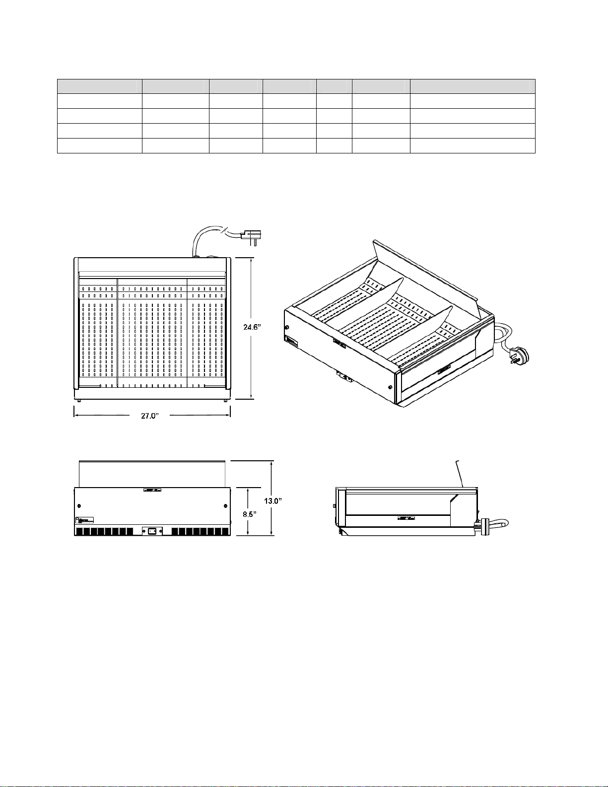
SPECIFICATIONS FOR 27000, 27001, 27002, 27017
Item # Voltage Amps Watts Hz Phase Cord/Plug
27000 208 VAC 21.6 4500 60 1 6’ NEMA L6-30P
27001 208 VAC 21.6 4500 60 1 6’ NEMA L6-30P
27002 240 VAC 18.8 4500 60 1 6’ NEMA L6-30P
27017* 208 VAC 21.6 4500 60 1 6’ NEMA L6-30P
*27017 includes drop-in shelf.
FFHS 27000 Series Service Manual
4
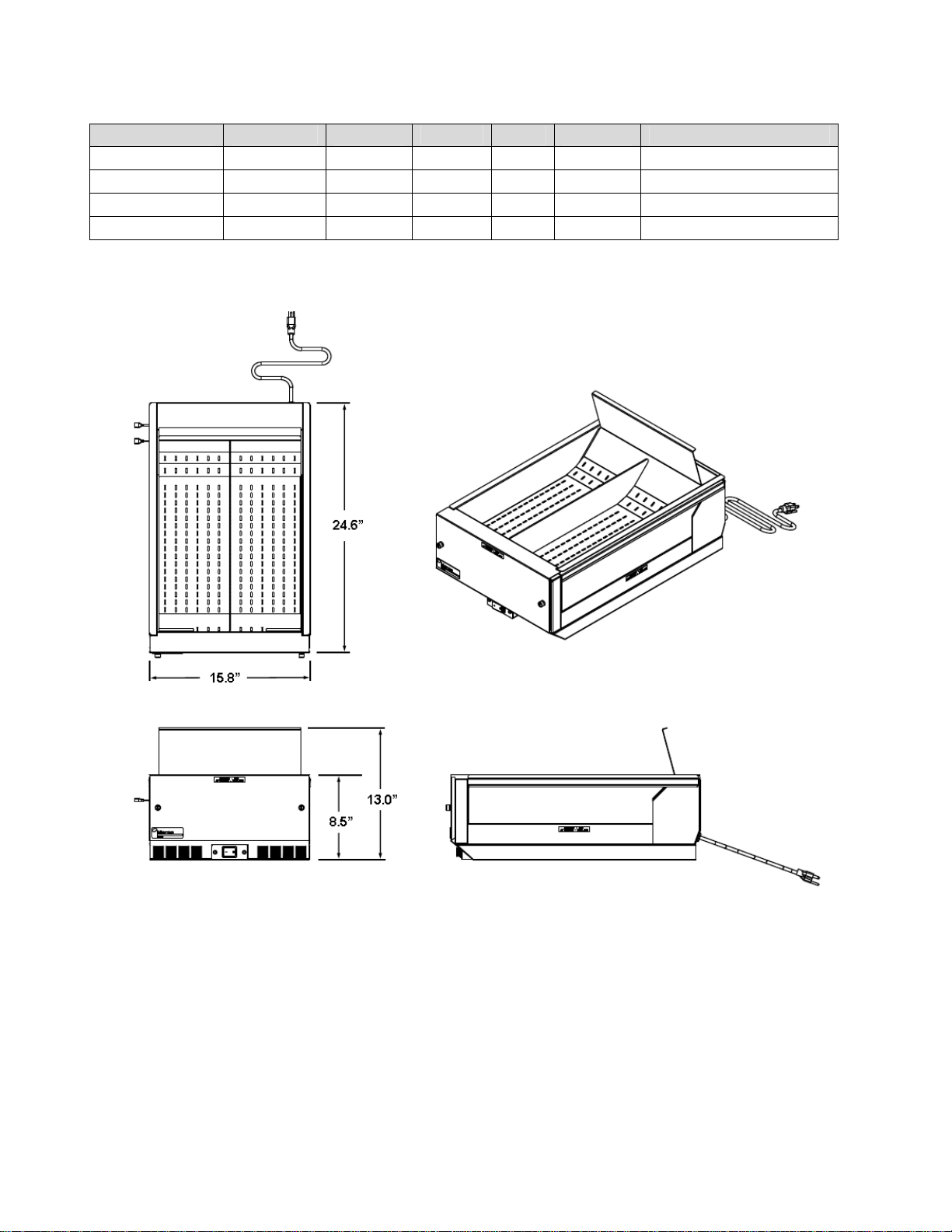
SPECIFICATIONS FOR 27007, 27008, 27012, 27016
Item Voltage Amps Watts Hz Phase Cord/Plug
27007 120 VAC 12.0 1450 60 1 5’ NEMA 5-15P
27008 (CE) 230 VAC 7.5 N/A
27012 120 VAC 15.4 1860 60 1 5’ NEMA 5-20P
27016* 120 VAC 12.0 1450 60 1 5’ NEMA 5-20P
*27016 includes drop-in shelf.

FFHS 27000 Series Service Manual 5
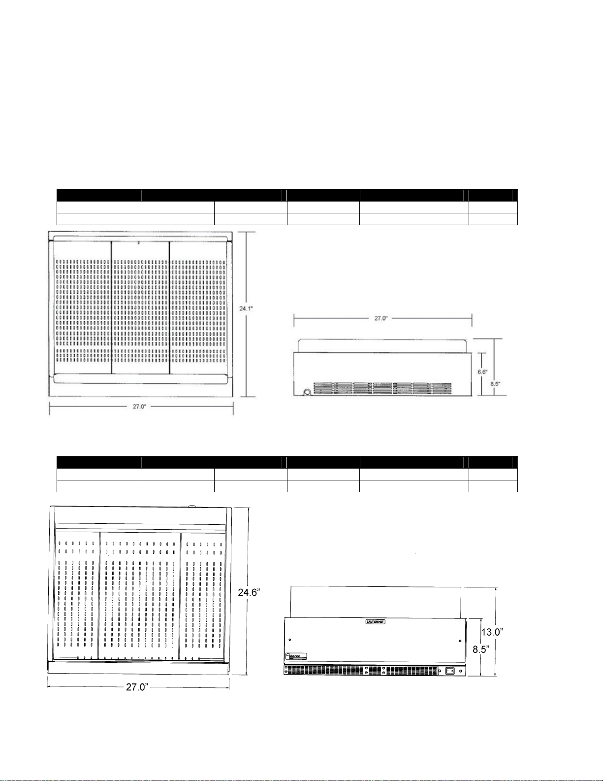
SPECIFICATIONS FOR 27016 with Remote Switch
SPECIFICATIONS FOR 27017 with Remote Switch
Remote
Switch
Pan
Assembly
Available only on model 27016
Pan
Assembly
Available only on model 27017
Remote
Switch

FFHS 27000 Series Service Manual
6
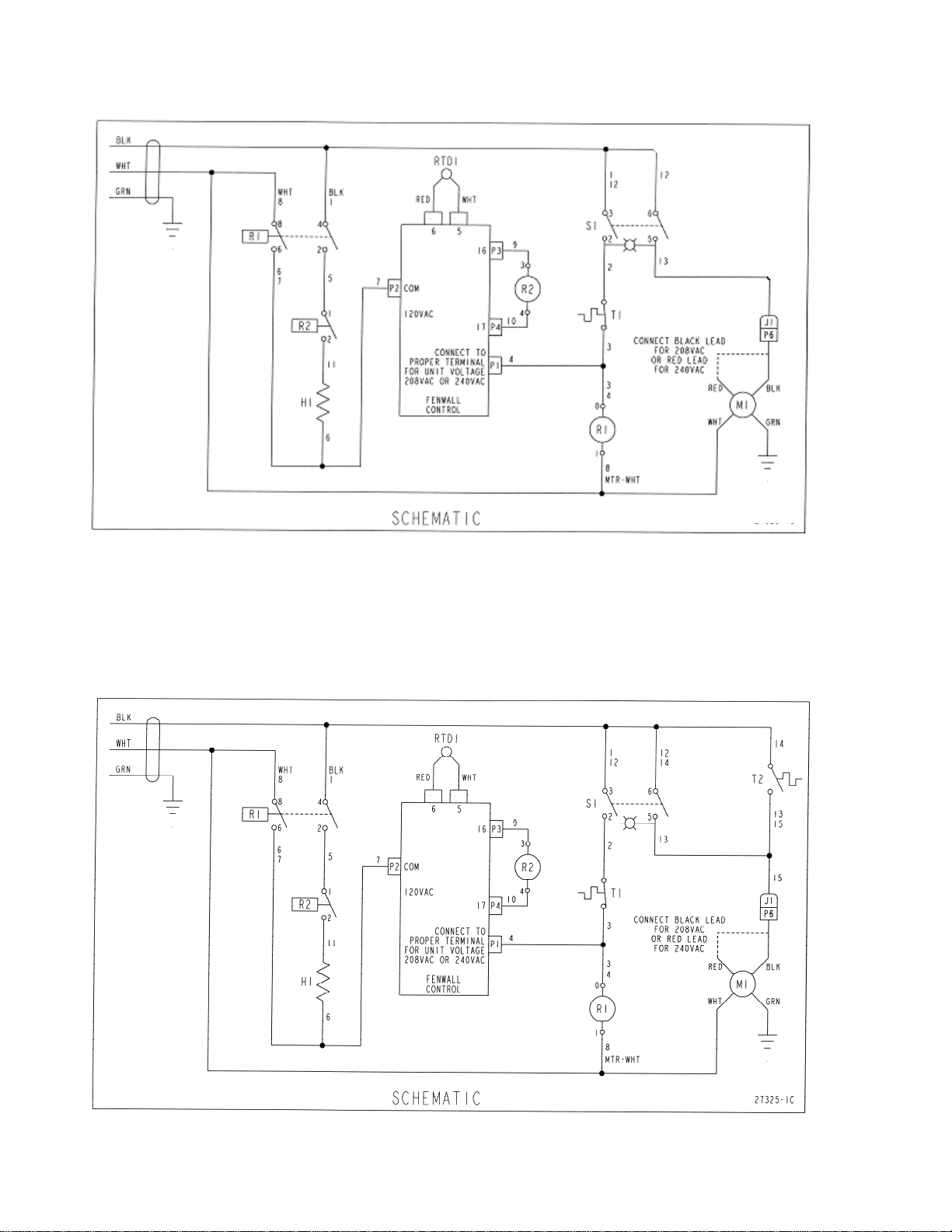
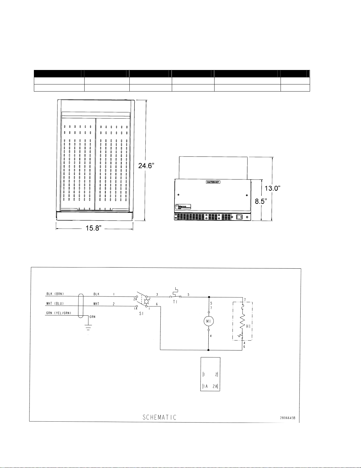
WIRING DIAGRAM FOR 27007, 27008, 27012, 27016
WIRING DIAGRAM FOR 27000, 27001, 27002

FFHS 27000 Series Service Manual 7
SEQUENCE OF OPERATIONS
MODELS 27000, 27001, 27002
Power Supply
Electrical power is supplied to the unit by a 3
conductor service for single phase.
Black conductor is hot.
White conductor is neutral.
Green and yellow conductor is ground.
Power is permanently supplied to one of the normally
open contacts of the main switch, also to the normally
open contacts of relay and the normally open cool
down thermostat.
Heating Circuit
Closing the main power switch supplies power to the
coils of relays, power is supplied to the main fan
motor. The contacts of R1 and R2 close supplying
power to the main heater.
Cool Down Circuit
As the temperature reaches 200°F, the cool down
thermostat closes. When the main switch is turned off,
the main fan will continue to run until the temperature
drops to 160°F.
SEQUENCE OF OPERATIONS
MODELS 27007, 27008, 27012, 27016
Power Supply
Electrical power is supplied to the unit by a 3
conductor service for single phase.
Black conductor is hot.
White conductor is neutral.
Green and yellow conductor is ground.
Power is permanently supplied to one of the normally
open contacts of the main switch also to one side of
the normally open contacts of the main heater relay.
Heating Circuit
Closing the main power switch feeds power through
the normally closed high limit thermostat to the coil of
the main relay. Its contacts now close supplying
power to the main heater. Also for air circulation
power is supplied to the main fan motor.

FFHS 27000 Series Service Manual
8
REMOVAL, INSTALLATION AND ADJUSTMENTS
(NEW STYLE CENTER SWITCH UNITS)
MODELS 27000, 27001, 27002
SWITCH, ON-OFF
1. Remove screws from face of switch mounting plate.
2. Disconnect wires from switch assembly. Mark wires for reinstallation.
3. Depress clips on side of switch and remove switch from panel.
4. Install new part, reassemble in reverse order, and check operation.
SWITCH, COOL-DOWN MOTOR
1. Lift and set aside pan tray and grease pan weldment.
2. Remove screws from both left and right outer formed panels.
3. Lift and set aside blower cover weldment.
4. Remove exhaust panel by sliding forward (toward on/off switch) and set panel aside.
5. Remove inner formed base by sliding forward (toward on/off switch).
6. Disconnect wires from end of cool-down motor switch. Mark wires for reinstallation.
7. Remove screws from cool-down motor switch to remove switch.
8. Install new part, reassemble in reverse order, and check operation.
HIGH LIMIT THERMOSTAT
1. Lift and set aside pan tray and grease pan weldment.
2. Remove fourteen (14) screws from both left and right outer formed panels.
3. Lift and set aside blower cover weldment.
4. Remove exhaust panel by sliding forward (toward on/off switch) and set panel aside.
5. Remove inner formed base by sliding forward (toward on/off switch).
6. Disconnect two (2) wires from end of high limit thermostat. Mark wires for reinstallation.
7. Remove two (2) screws from the high limit to remove thermostat.
8. Install new part, reassemble in reverse order, and check operation.
POWER CORD 250V 30A
1. Lift and set aside pan tray and grease pan weldment.
2. Remove screws from both left and right outer formed panels.
3. Lift and set aside blower cover weldment.
4. Disconnect power cord L1 and L2 wires from wire terminal connections. Mark wires for
reinstallation.
5. Remove ground nut from power cord ground wire.
6. Compress cord strain relief to remove power cord from bracket.
7. Install new part, reassemble in reverse order, and check operation.
CAUTION:
!
Disconnect power supply before servicing or cleaning this toaster. Safeguard power
so it cannot be accidentally restored. Failure to do so could result in dismemberment,
electrocution, or fatal injury.

FFHS 27000 Series Service Manual 9
HEATER 208V, 240V
1. Lift and set aside pan tray and grease pan weldment.
2. Remove screws from both left and right outer formed panels.
3. Lift and set aside blower cover weldment.
4. Remove exhaust panel by sliding forward (toward on/off switch) and set panel aside.
5. Remove inner formed base by sliding forward (toward on/off switch).
6. Remove screws from element bracket.
7. Loosen screws from air duct base next to element bracket for element removal.
8. Disconnect wires from heater and remove heater. Mark wires for reinstallation.
9. Install new part, reassemble in reverse order, and check operation.
BLOWER
1. Lift and set aside pan tray and grease pan weldment.
2. Remove screws from both left and right outer formed panels.
3. Lift and set aside blower cover weldment.
4. Disconnect wires from blower. Mark wires for reinstallation.
5. Remove nuts from base of blower assembly and remove blower assembly.
6. Install new part, reassemble in reverse order, and check operation.
POWER RELAY
1. Lift and set aside pan tray and grease pan weldment.
2. Remove screws from both left and right outer formed panels.
3. Lift and set aside blower cover weldment.
4. Disconnect wires from relay. Mark wires for reinstallation.
5. Remove screws from relay and remove power relay.
6. Install new part, reassemble in reverse order, and check operation.

FFHS 27000 Series Service Manual
10
REMOVAL, INSTALLATION AND ADJUSTMENTS
(NEW STYLE CENTER SWITCH UNITS)
MODELS 27007, 27008, 27012, 27016
SWITCH, ON-OFF
1. Remove two (2) screws from face of switch mounting plate.
2. Disconnect three (3) wires from switch assembly. Mark wires for reinstallation.
3. Depress clips on side of switch and remove switch from panel.
4. Install new part, reassemble in reverse order, and check operation.
POWER CORD 120V
1. Lift and set aside pan tray and grease pan weldment.
2. Remove fourteen (14) screws from both left and right outer formed panels.
3. Lift and set aside blower cover weldment.
4. Disconnect power cord neutral and L1 wires from in-line wire terminal connections. Mark wires for
reinstallation.
5. Remove ground nut from power cord ground wire.
6. Compress cord strain relief to remove power cord from bracket.
7. Install new part, reassemble in reverse order, and check operation.
HEATER 120V
1. Lift and set aside pan tray and grease pan weldment.
2. Remove fourteen (14) screws from both left and right outer formed panels.
3. Lift and set aside blower cover weldment.
4. Remove six (6) screws from air intake baffle.
5. Remove two (2) screws from bottom of exhaust panel and set panel aside.
6. Remove inner formed base by sliding forward (toward on/off switch).
7. Remove three (3) screws from base of blower assembly.
8. Remove two (2) screws from both left and right air duct fillers.
9. Slide out blower and heater assembly from blower seal bracket.
10. Remove four (4) screws from side of heater to separate heater from blower.
11. Disconnect two (2) wires from heater and remove heater. Mark wires for reinstallation. Note the
path of the wires for reinstallation.
12. Install new part, reassemble in reverse order, and check operation.
CAUTION:
!
Disconnect power supply before servicing or cleaning this toaster. Safeguard power
so it cannot be accidentally restored. Failure to do so could result in dismemberment,
electrocution, or fatal injury.

FFHS 27000 Series Service Manual 11
BLOWER
1. Lift and set aside pan tray and grease pan weldment.
2. Remove fourteen (14) screws from both left and right outer formed panels.
3. Lift and set aside blower cover weldment.
4. Disconnect two (2) wires from blower. Mark wires for reinstallation.
5. Remove three (3) screws from base of blower assembly.
6. Remove two (2) screws from both left and right air duct fillers.
7. Slide out blower and heater assembly from blower seal bracket.
8. Remove four (4) screws from side of heater to separate heater from blower.
Install new part, reassemble in reverse order, and check operation.
POWER RELAY
1. Lift and set aside pan tray and grease pan weldment.
2. Remove screws from both left and right outer formed panels.
3. Lift and set aside blower cover weldment.
4. Disconnect wires from relay. Mark wires for reinstallation.
5. Remove screws from relay and remove power relay.
6. Install new part, reassemble in reverse order, and check operation.

FFHS 27000 Series Service Manual
12
PARTS BREAKDOWN – FFHS-16
MODELS 27007, 27008, 27012, 27016
LETTER PART # DESCRIPTION
A 27511SP Lighted Rocker Switch
B 340091 Panel, Switch, FFHS
C 340092 Air Duct Subassembly
D 27120 Outer Panel, Left
E 27045-1 Divider
27375-4 Tray, Full Pan, welded – models 27007, 27008, 27012, 27014
F 27375-5 Tray, Full Pan, welded – model 27016
27370-3 Pan, Grease, Weldment – models 27007, 27008, 27012, 27016
G 27370-4 Pan, Grease, Weldment – model 27014
H 27080-3 Inner Base Formed
I 27125 Outer Panel, Right
J 340024 Bush., .875, Snap Universal
340088 T-Disc, 240/275 F, NC
K 000496 Copaco Paper, .015” x 2” x 7.75”
L 27115-3 Blower Cover Weldment
340028 Blower Assembly – models 27007, 27014, 27016
340093 Blower Assembly – model 27008
340094 Blower Assembly – model 27012
M
340063 Heater, 1850 W 120V only – model 27012
340095 Power Cord – models 27007, 27014
340096 Power Cord – model 27012
N 340097 Power Cord – model 27016
O 340089 Relay, DPST, 25A, 120V
P 340098 Relay Bracket, FFHS-16
Q 000171 Heyco Bushing
R 340099 Front Cover Assembly
S 340100 Exhaust Vent Subassembly
T 000696 Label, “Caution Hot” (English/French)
Not Shown 10001503 Remote Switch – model 27016 only
Not Shown 27506SP Heater – models 27007, 27014, 27016
Not Shown 4040266-2 Heater – model 27008
Not Shown 4040266-3 Heater – model 27012
Not Shown 4060505-1 Blower – models 27007, 27014, 27016
Not Shown 4060505-2 Blower – model 27008
Not Shown 4060505-3 Blower – model 27012

FFHS 27000 Series Service Manual 13
A
B
C
D
E
F
G
H
I J K
L
M
N
O
P
R
S
T
Q
GENERAL VIEW – FFHS-16
MODELS 27007, 27008, 27012, 27016

FFHS 27000 Series Service Manual
14
PARTS BREAKDOWN – FFHS-27
MODELS 27000, 27001, 27002, 27017
LETTER PART # DESCRIPTION
A 340087 Switch, Sealed, Illum, Grn
B 340091 Panel, Switch, FFHS
C 340101 Air Duct Subassembly
D 27120 Outer Panel, Left
E 27045-1 Divider
340131 Tray, Full Pan, Welded – models 27000 & 27002
F 27375-2 Tray, Full Pan, Welded – model 27001
G 27370-1 Pan, Grease, Weldment
H 27080-1 Inner Base Formed
I 27125 Outer Panel, Right
J 340024 Bush., .875 Snap Universal
K 000496 Copaco Paper, .015”x2”x 7.75”
L 27115-1 Blower Cover Weldment
340058 Blower / Heater Assembly – models 27000 & 27001
340061 Blower / Heater Assembly – model 27002
340060 Tang Blower only – models 27000, 27001, 27002
340059 Heater, 4500 W 208V only – models 27000 & 27001
M
340062 Heater, 4500 W 240V only – model 27002
N 27280 Cord Assembly, FFHS 208/240V
O 27240 Power Relay, 240V
P 340102 Relay Bracket, FFHS-27
Q 27235 Bush., STR. REL., 10/3, S
R 340103 Front Cover Assembly
S 340104 Exhaust Vent Subassembly
T 000696 Label, Caution-Hot, FR/ENG
Not Shown 27485 Motor Cool-down Switch
Not Shown Drop-In Shelf – model 27017 only
Not Shown 10002777-01 Heater – models 27000 & 27002
Not Shown 10002777-02 Heater – model 27001
Not Shown 10002776-01 Blower – models 27000 & 27002
Not Shown 10002776-01 Blower – model 27001

FFHS 27000 Series Service Manual 15
GENERAL VIEW – FFHS-27
MODELS 27000, 27001, 27002, 27017
A B
C
D
E
F
G
H
I
JK L
M
N
P
Q
R
S
T
O

FFHS 27000 Series Service Manual
16
THE FOLLOWING MODELS (WITH RIGHT-SIDE SWITCHES) ARE NO LONGER IN PRODUCTION.
FFHS 27000 Series Service Manual 17
SPECIFICATIONS 27000, 27002 S/N 1083327 & BELOW
Item # Voltage Amps Watts Cord/Plug Net Wt.
27000 208 VAC 26.4 5500 6’ NEMA L6-30P 76 lbs.
27002 240 VAC 22.9 5500 6’ NEMA L6-30P 76 lbs.
SPECIFICATIONS 27000, 27002 S/N 1083328 & ABOVE
Item # Voltage Amps Watts Cord/Plug Net Wt.
27000 208 VAC 24.0 5500 6’ NEMA L6-30P 66 lbs.
27002 240 VAC 22.9 5500 6’ NEMA L6-30P 66 lbs.
SEQUENCE OF OPERATION 27000, 27002
Power is permanently supplied to the normally open contacts of the main relay. Power is also supplied to the
normally open power switch. Closing the power switch supplies power through the normally closed hi-limit
thermostat to the electronic control board. Power is also supplied to the coil of the main relay. When the main
relay is energized, the contacts close supplying power to the contacts of the solid state relay. When the
electronic control is energized, voltage is supplied to the blower motor. The RTD probe senses air
temperature. The electronic temperature control supplies power to the solid state relay. When the relay
contacts close, power is supplied to the heating element. The solid state relay will cycle on and off to maintain
the proper temperature.
FFHS 27000 Series Service Manual
18
WIRING DIAGRAM – MODELS 27000, 27002 S/N 1083327 & BELOW
WIRING DIAGRAM – MODELS 27000, 27002 S/N 1083328 & ABOVE
FFHS 27000 Series Service Manual 19
SPECIFICATIONS 27007, 27012
Item Voltage Amps Watts Cord/Plug Net Wt.
27007 120 VAC 12.3 1450 5’ NEMA 5-15P 44 lbs.
27012 120 VAC 15.7 1850 5’ NEMA 5-20P 44 lbs.
WIRING DIAGRAM – MODELS 27007, 27012
SEQUENCE OF OPERATION 27007, 27012
Power is supplied to the normally open power switch. Closing the power switch supplies power through
the normally closed hi-limit thermostat to the blower motor and to the heating element.

FFHS 27000 Series Service Manual
20
PARTS BREAKDOWN – MODELS 27000, 27002 S/N 1083327 & BELOW
LETTER PART # DESCRIPTION
A 27155 Tray, Weldment
B 27355 Drip Pan
C 27130 Inner Panel (left)
27135 Inner Panel (right)
D 27120 Outer Panel (left)
27125 Outer Panel (right)
E 27080 Inner Base
F 27170 Insulation, Air Duct
G 27050 Air Baffle
H 27025 Element Top Panel
I 27060 Divider Plate (left)
27065 Divider Plate (right)
J 27230 Plug, Twist Lock, 30A, 250V, not CE
370019 Cord and Plug, 50A, (Canada only)
K 27110 Element, Heater 208V
27040 Element, Heater 240V
L 27115 Motor Housing Cover
M 27420 On / Off Switch
N 27185 Electronic Control
O 27175 Bracket (SSR & Control)
P 27075 Blower Motor
Q 27240 Power Relay
R 27235 Bushing, Strain Relief (not CE)
27370 Bushing, Strain Relief (CE only)
S 27010 Base
T 27280 Cord, (not CE)
NLA Cord, (CE only)
U 27030 Spacer Plate, Insulation, Top
V 27090 Insulation, Base
W 27195 Air Scoop
X 27035 Insulation, Front
Y 27095 Exhaust Panel
Z 27225 Exhaust Panel Guard
AA 27145 Captive Screw
BB 27180 Solid State Relay
Not Shown 27182 Heat Sink
Not Shown 27275 Captive Screw Retainer
Not Shown 41087 Leg, 1”
Not Shown 27045 Pan Dividers
Not Shown 27320 Grease Deflector (left)
Not Shown 27315 Grease Deflector (right)
Not Shown 27055 Hi-Limit
Not Shown 27205 RTD Probe
This manual suits for next models
20
Other Merco Commercial Food Equipment manuals


Popular Commercial Food Equipment manuals by other brands


etol
etol Blu'box 13 Eco Original user manual

Traulsen
Traulsen G-Series owner's manual

Hatco
Hatco HEATMAX RHW Series Installation and operating manual

Vulcan-Hart
Vulcan-Hart VHU Series Service manual

Waldorf
Waldorf Bold PCB8140E-7 Installation and operating manual

SAINT-GOBAIN
SAINT-GOBAIN Norton CM 35 Mini Clipper operating instructions